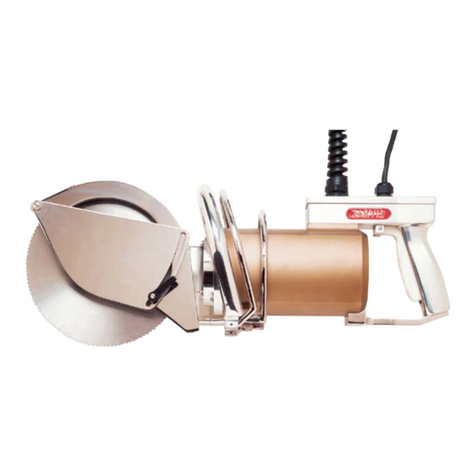
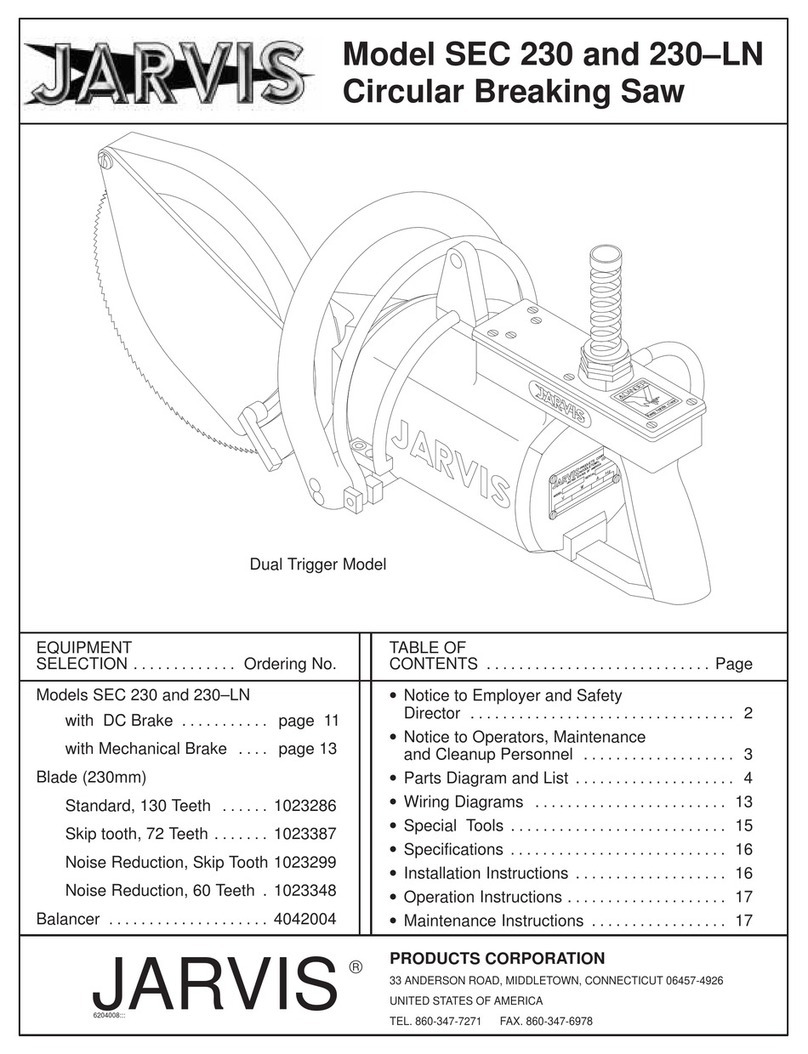
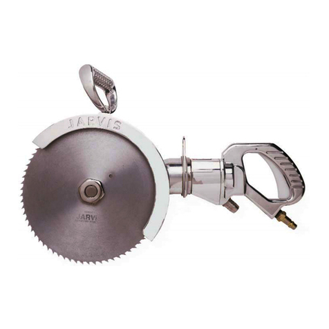
Jarvis SEC 180-2 User manual

TABLE OF
CONTENTS Page............................
Models SEC 180--2
115V, 1 Phase, Adjustable Depth Gage 4004231
230V, 1 Phase, Adjustable Depth Gage 4004232
115V, 1 Phase, Indexing Depth Gage 4004250
230V, 1 Phase, Indexing Depth Gage 4004243
Models SEC 230--2
115V, 1 Phase, 4004234....................
230V, 1 Phase, 4004235....................
Models SEC 280--2
115V, 1 Phase, 4004237....................
230V, 1 Phase, 4004238....................
Balancer
SEC 180--2 4042040........................
SEC 230--2, 280--2 4042037.................
PRODUCTS CORPORATION
33 ANDERSON ROAD, MIDDLETOWN, CONNECTICUT 06457-4926
TEL. 860-347-7271 FAX. 860-347-6978 www.jarvisproducts.com
Model SEC 180--2, 230--2, 280--2
Circular Breaking Saws
EQUIPMENT
SELECTION Ordering No.......................
Safety Messages to Employer and Safety
Director 2.................................
Safety Messages to Operators, Maintenance
and Cleanup Personnel 3...................
Parts Diagram and List 4......................
Wiring Diagram 7............................
Specifications 8..............................
Installation Instructions 8......................
Operation Instructions 8......................
Maintenance Instructions 9....................
SEC 180--2
Adjustable
Depth Gage
SEC 230--2
SEC 280--2
SEC 180--2
Indexing
Depth Gage
JARVIS®
6204015::

safety messages to employer
and safety director
page 2 of 16
Model SEC 180--2, 230--2 and 280--2
JARVIS PRODUCTS CORPORATION
33 ANDERSON ROAD, MIDDLETOWN, CONNECTICUT 06457-4926
TEL. 860-347-7271 FAX. 860-347-6978 www.jarvisproducts.com
6204015::
®
1. Ensure that all employees who use this tool are trained in the proper use of this tool and are aware of
the dangers that may arise if they do not follow procedures outlined in this brochure.
2. Enclosed are four (4) copies of “NOTICE TO OPERATORS, MAINTENANCE AND CLEANUP
PERSONNEL”. Post one copy on the employees’ bulletin board; give one copy to the operator(s);
give one copy to the maintenance foreman; and give one copy to the sub-contract cleanup / internal
cleanup foreman. Additional copies will be provided upon request.
3. The tool is designed and intended to be powerful. This fact should be obvious to your employees, but
you must emphasize it to them.
4. Ensure that all employees are instructed not to walk in front of the tool during its use.
5. Ensure that eye protection is worn in accordance with OSHA’s eye and face protection requirements
(29 CFR 1910.147) when operating the tool.
6. Ensure that proper procedures are established in accordance with OSHA’s lockout/tagout procedures
(29 CFR 1910.147) to prevent accidental startup or release of stored energy.
7. Follow our installation and maintenance instructions for proper installation and care of the tool.
8. Never make modifications or alterations to the tool. Replace any missing or illegible labels.
9. Remove and repair any tool that malfunctions. All personnel must be instructed to remove any
malfunctioning equipment.
10. Avoid injury. Do not permit the tool to be misused.
11. If you resell or distribute a Jarvis product, you must provide the purchaser with the appropriate safety
sheets and tool brochure. Additional copies of safety sheets and tool brochures will be provided upon
request.
SAFETY MESSAGES TO EMPLOYER AND SAFETY DIRECTOR
AVOID INJURY
Keep hands clear.

safety messages to operators, maintenance
and cleanup personnel
Model SEC 180--2, 230--2 and 280--2
page 3 of 16
JARVIS PRODUCTS CORPORATION
33 ANDERSON ROAD, MIDDLETOWN, CONNECTICUT 06457-4926
TEL. 860-347-7271 FAX. 860-347-6978 www.jarvisproducts.com
6204015::
®
1. Disconnect the power supply in accordance with OSHA’s lockout/tagout procedures (29 CFR
1910.147) before making any blade changes.
2. Disconnect the power supply in accordance with OSHA’s lockout/tagout procedures (29 CFR
1910.147) before performing any repair or maintenance.
3. Disconnect the power supply - or have the power supply disconnected - in accordance with OSHA’s
lockout/tagout procedures (29 CFR 1910.147) before performing any cleanup.
4. Disconnect the power supply when the tool is not being used.
5. Always wear eye protection in accordance with OSHA’s eye and face protection requirements (29 CFR
1910.133) when operating the tool.
6. Always use both hands when starting and operating the tool to avoid the risk of possible “kick back”
or “recoil”. Continue holding the tool with both hands until the saw blade comes to a complete stop.
7. Never put fingers, hands or other parts of the body on the cutting edge or within the cutting path of the
tool.
8. Never allow people to walk in front of the tool during its use.
9. Never allow people to hold / restrain the carcass while operating the tool.
10. Test the tool prior to use or daily. Depress the trigger and the tool should start. Release the trigger
and the tool should stop. If the tool malfunctions, remove it from service and report or repair it immedi-
ately.
11. Test the brake prior to use or daily. After releasing the trigger, the tool should stop within 2.5 seconds.
If the tool malfunctions, remove it from service and report or repair it immediately.
12. Never depress the trigger unless you want to use or test the tool.
13. Never make modifications or alterations to the tool. Replace any missing or illegible labels.
SAFETY MESSAGES TO OPERATORS, MAINTENANCE AND CLEANUP
PERSONNEL
REMOVE ANY MALFUNCTIONING TOOL FROM SERVICE
REPORT ANY PROBLEMS TO YOUR SUPERVISOR
Keep hands clear.

parts diagram and list
page 4 of 16
Model SEC 180--2, 230--2 and 280--2
JARVIS PRODUCTS CORPORATION
33 ANDERSON ROAD, MIDDLETOWN, CONNECTICUT 06457-4926
TEL. 860-347-7271 FAX. 860-347-6978 www.jarvisproducts.com
6204015::
®
1 1026265 Ring Gear 1
2 1026255 Pinion Gear 1
3 1030094 Key 1
4 1021306 Ball Bearing 1
5 1029423 Spacer 1
6 1021155 Ball Bearing 1
7 1061801 Brake Drum 1
8 1002498 Brake Cover 1
9 1014193 Compression Spring 3
10 1004241 Split Lock Washer 3
11 1055020 Socket Head Cap Screw 1
12 1020362 Planetary Gear Shaft 3
13 1004415 Thrust Washer 6
14 1013215 Retaining Ring 4
1013215+ Retaining Ring 3
15 1021457 Needle Bearing 3
16 3026072 Planetary Idler Gr. w/item 15 3
17 1004426 Hub Retaining Washer 1
18 1055931 Cheese Head Screw 6
19 1031044 Planetary Carrier Hub 1
20 1010455 Dowel Pin 3
21 1071042 Brake Shoe 3
22 1035648 Oil Seal 1
23 1055918 Flat Head Slotted Screw 3
24 1035486 Oil Seal 1
25 1013232 Retaining Ring 1
26 1004230 Split Lock Washer 4
27 1055055 Hex Head Screw 4
28 1038022 Grease Fitting 2
29 1010432 Dowel Pin 1
1010432+ Dowel Pin 3
ITEM PART NO. PART NAME QTY ITEM PART NO. PART NAME QTY
Figure A
SEC 180--2
Gear Housing and
Brake Assemblies
30 1016654 Gear Housing with item 28 1
31 1027077dStud 1
32 1007390dWing Nut 1
33 1032659SRub Plate 1
34 1026252 Crown Gear 1
35 1030066 Key 1
36 1020373 Crown Gear Shaft 1
37 1021359 Ball Bearing 1
38 1013296 Retaining Ring 1
39 1035547 Oil Seal 1
40 1002514 Gear Housing Cover 1
41 1023272 Blade, 98 Teeth 1
1023332 Blade, 48 Teeth
42 1007389 Blade Nut 1
43 3025011SDepth Gage, Indexing 1
44 1033013SIndex Block 1
45 1055901SOval Head Screw 2
46 1054172SThumb Screw 1
47 8039099 Blade Locking Pin 1
48 1004425 Slinger 1
49 1055410 Cheese Head Screw 3
50 1013290 Retaining Ring 1
51 1021035 Ball Bearing 1
52 1025057dDepth Gage, Non--Indexing 1
53 1055945dHex Head Screw 1
54 1004262dWasher 1
55 1004020dFlat Washer 1
56 1017401 Name and Info Label 1
57 1055616 Cheese Head Screw 4
S
S
SSFor indexing model only
dFor non--indexing models only
d
d
d
d
S
S
DWrench 8039197 is provided
D
d
d
+ SEC 230--2 and SEC 280--2

parts diagram and list
Model SEC 180--2, 230--2 and 280--2
page 5 of 16
JARVIS PRODUCTS CORPORATION
33 ANDERSON ROAD, MIDDLETOWN, CONNECTICUT 06457-4926
TEL. 860-347-7271 FAX. 860-347-6978 www.jarvisproducts.com
6204015::
®
Figure B
SEC 230--2 and SEC 280--2
Gear Housing and Brake Assemblies
58 1026244* Pinion Gear 1
1026250** Pinion Gear
59 1021415 Ball Bearing 1
60 1013194 Retaining Ring 2
61 1007382 Flange Nut 1
62 1032636 Flange Plate 1
63 1055044 Hex Head Screw 4
64 1038006 Grease Fitting 2
65 1055238 Hex Head Screw 4
66 1016639* Shaft Housing with item 64 1
1016648** Shaft Housing with item 64
67 1004414 Hub Retaining Washer 1
68 3026068 Planetary Idler Gr. w/item 15 3
69 1031039 Planetary Carrier Hub 1
70 1026248 Ring Gear 1
71 1021392 Ball Bearing 1
72 1004113 Plain Washer 4
73 1016638 Gear Housing with item 64 1
74 1021035 Ball Bearing 1
75 1026245 Crown Gear 1
76 1020363 Crown Gear Shaft 1
77 1030089 Key 2
ITEM PART NO. PART NAME QTY ITEM PART NO. PART NAME QTY
78 1021350 Ball Bearing 1
79 1013247 Retaining Ring 1
80 1035544 Oil Seal 1
81 1002496 Gear Housing Cover 1
82 1055835 Flat Head Slotted Screw 3
83 1035649 Blade Guard Gasket 1
84 1055746 Socket Head Cap Screw 2
85 1004330 Blade Retaining Washer 1
86 1023288* Blade, 150 Teeth 1
1023388* Blade, Standard Skip Teeth
1023393* Blade, 72 Teeth
1023295* Blade, Noise Reduction
1023286** Blade, 130 Teeth
1023387** Blade, Skip Teeth, 72 Teeth
1023299** Blade, Noise Reduction
1023348** Blade, Noise Red, 60 Teeth
87 1004413 Slinger 1
88 1024273* Blade Guard 1
89 1024272** Blade Guard 1
90 1032359** Depth Gage Plate 1
91 1018128** Gage Locking Lever 1
92 1054134** Depth Gage Screw 1
* SEC 280--2 only
** SEC 230--2 only
*
***
**
D
DWrench 8039147 is provided
**
**
**
**
*

parts diagram and list
page 6 of 16
Model SEC 180--2, 230--2 and 280--2
JARVIS PRODUCTS CORPORATION
33 ANDERSON ROAD, MIDDLETOWN, CONNECTICUT 06457-4926
TEL. 860-347-7271 FAX. 860-347-6978 www.jarvisproducts.com
6204015::
®
Figure C
SEC 180--2, SEC 230--2 and SEC 280--2
Motor and Front Handle Assemblies
93 1019235 Front Handle 1
94 1055261 Pan Head Tapping Screw 4
95 1016640 Bearing Housing 1
96 1042541 Hanger Bracket 1
97 1036321 Alignment Bushing 2
98 1002497 Fan Housing with item 97 1
99 1026247 Planetary Pinion Gear 1
100 1021029 Ball Bearing 1
101 1063960 Armature, 230V 1
1072030 Armature, 115V
102 1021192 Ball Bearing 1
103 1002494 Motor Housing Cover 1
104 1055268 Slot Head Screw 2
105 1063961 Stator, 1800W, 230V 1
1072031 Stator, 1800W, 115V
106 1017083 Danger Label 1
107 1002499 Brush Cover 2
108 1055262 Pan Head Tapping Screw 2
109 1035650 Brush Cover Gasket 2
110 1047015 Motor Brush, Auto Sensing 1
1047014 Motor Brush, Standard 1
111 1063962 Brush Holder, 1800W, 230V 2
1072032 Brush Holder, 1800W, 115V
112 1002495 Rear Motor Cover 1
113 1016637 Motor Housing with item 106 1
114 1007299 Hex Nut 2
ITEM PART NO. PART NAME QTY
115 1004232 Split Lock Washer 2
116 1055929 Hex Head Screw 2
117 1055604 Hex Head Screw 2
118 1019135 Front Handle 1
119 1055998 Hex Head Screw 2
120 1042552 Hanger Bracket 1
121 1004231 Split Lock Washer 4
122 1007274 Hex Nut 2
123 1024317 Fan Guard 1
124 1063958 Armature, 230V 1
1072028 Armature, 115V
125 1071058 Air Guide Plate 1
126 1055400 Pan Head Tapping Screw 2
127 1063959 Stator, 1400W, 230V 1
1072029 Stator, 1400W, 115V
128 1063963 Brush Holder, 1400W, 230V 2
1072032 Brush Holder, 1400W, 115V
129 1026263 Planetary Pinion Gear 1
130 1035296 O--ring 1
131 1016814 Front Bearing Housing 1
132 1055379 Pan Head Tapping Screw 4
133 1002512* Front Motor Cover 1
ITEM PART NO. PART NAME QTY
SEC 180--2 SEC 230--2
and
SEC 280--2
* not used in current SEC 180--2 tools
*
*
*

parts diagram, list
and wiring diagram
Model SEC 180--2, 230--2 and 280--2
page 7 of 16
JARVIS PRODUCTS CORPORATION
33 ANDERSON ROAD, MIDDLETOWN, CONNECTICUT 06457-4926
TEL. 860-347-7271 FAX. 860-347-6978 www.jarvisproducts.com
6204015::
®
134 1019237 Left Side Rear Handle 1
135 1002500 Switch Cover Boot 1
136 1055263 Pan Head Screw 2
137 1012143 Cord Clamp 1
138 1001195 Electric Cord 1
139 1063965 Strain Relief 1
140 1019236 Right Side Rear Handle 1
141 1055265 Pan Head Screw 4
142 1063964 Capacitor 1
143 1005088 Electric Switch 1
144 1055264 Pan Head Screw 4
ITEM PART NO. PART NAME QTY
Figure D
SEC 180--2, SEC 230--2 and SEC 280--2
Rear Handle Assembly
Figure E
Wiring Diagram

specifications, installation
and operation instructions
page 8 of 16
Model SEC 180--2, 230--2 and 280--2
JARVIS PRODUCTS CORPORATION
33 ANDERSON ROAD, MIDDLETOWN, CONNECTICUT 06457-4926
TEL. 860-347-7271 FAX. 860-347-6978 www.jarvisproducts.com
6204015::
®
SPECIFICATIONS
SEC 180--2
Motor Power 1.9 hp 1400 W
Operating Voltages 230 / 115 V, 1 phase, 50 / 60 Hz
Full Load Amps 6.5A @ 230V
13A @ 115V
Blade Speed 1650 rpm
Control Handles
Single Trigger / Dual Handles Electric
Brake Mechanical
Blade Diameter 7.1 in 180 mm
Cutting Depth 2.6 in 66 mm
Overall Length 21.5 in 546 mm
Weight 14.6 lbs 6.6 kg
Vibration less than (<) 126 dB < 2 m/sec2
Noise (one meter from tool) < 85 dBa
SEC 230--2 / SEC 280--2
Motor Power 2.4 hp 1800 W
Operating Voltages 230 / 115 V, 1 phase, 50 / 60 Hz
Full Load Amps 8.4A @ 230V
16.8A @ 115V
Blade Speed 1300 rpm
Control Handles
Single Trigger / Dual Handles Electric
Brake Mechanical
Blade Diameter
SEC 230--2 9.1 in 230 mm
SEC 280--2 11.0 in 280 mm
Cutting Depth
SEC 230--2 3.0 in 76 mm
SEC 280--2 4.0 in 102 mm
Overall Length
SEC 230--2 22.5 in 572 mm
SEC 280--2 30 in 762 mm
Weight
SEC 230--2 22 lbs 10 kg
SEC 280--2 24 lbs 11 kg
Vibration less than (<) 123 dB < 1.3 m/sec2
Noise <85 dBa
INSTALLATION INSTRUCTIONS
ALWAYS DISCONNECT THE POWER SUPPLY IN ACCOR-
DANCE WITH OSHA’S LOCKOUT/TAGOUT PROCEDURES
(29 CFR 1910.147) BEFORE PERFORMING ANY REPAIRS OR
MAINTENANCE. ALL WIRING MUST BE DONE IN ACCOR-
DANCE WITH NATIONAL, STATE AND LOCAL ELECTRICAL
CODES.
Refer to Figures A to D on pages 4 through 7 for refer-
enced items.
1 Install a balancer above the work station on a trolley.
1.1 The trolley should have sufficient travel to allow
the operator to reach the entire work area.
2 Suspend the tool from the balancer.
2.1 Adjust the balancer to the operator’s preference.
3 Install plug of your choice to end of electrical cord
(item 138).
4 Plug the tool into appropriate power supply outlet.
OPERATION INSTRUCTIONS
1 Plug in the tool.
2Each day before you begin operation, perform the
following:
2.1 Make sure that tool moves freely on its balancer.
2.2 Make sure that the saw is working correctly.
Depress the trigger and the tool should start.
Release the trigger and the tool should stop
within 3 seconds. If the tool malfunctions, re-
move it from service and report the problem to
your supervisor immediately.
Always use two hands when starting and stopping the
tool. Continue holding the tool with two hands until the
saw blade comes to a complete stop.
3 Make the cut:
3.1 Position the saw.
3.2 Depress the trigger and make the cut.
3.3 When the desired length of cut is reached, re-
lease the trigger. This will stop the blade from
rotating.
3.4 Withdraw the saw from the carcass.
4 Unplug the tool.

maintenance instructions
Model SEC 180--2, 230--2 and 280--2
page 9 of 16
JARVIS PRODUCTS CORPORATION
33 ANDERSON ROAD, MIDDLETOWN, CONNECTICUT 06457-4926
TEL. 860-347-7271 FAX. 860-347-6978 www.jarvisproducts.com
6204015::
®
MAINTENANCE INSTRUCTIONS
ALWAYS DISCONNECT THE POWER SUPPLY IN ACCOR-
DANCE WITH OSHA’S LOCKOUT/TAGOUT PROCEDURES
(29 CFR 1910.147) BEFORE INSTALLING OR REMOVING A
BLADE. ALWAYS DISCONNECT THE POWER SUPPLY IN
ACCORDANCE WITH OSHA’S LOCKOUT/TAGOUT PROCE-
DURES (29 CFR 1910.147) BEFORE PERFORMING ANY RE-
PAIRS OR MAINTENANCE.
Refer to Figures A to D on pages 4 through 7 for refer-
enced items.
1 PRIOR TO USE OR DAILY:
1.1 Model 180--2.
1.1.1 Add Jarvis 1315 White Grease to grease fit-
tings (item 28) located on on gear housing
(item 30).
1.2 Models 230--2 and 280--2.
1.2.1 Add Jarvis 1315 White Grease to grease fit-
tings (item 64) located on shaft housing
(item 66) and gear housing (item 73).
1.3 Make sure that the saw is working correctly.
Depress the trigger and the tool should start.
Release the trigger and the tool should stop
within 3 seconds. If the tool malfunctions, re-
pair or remove it from service immediately.
Always use two hands when starting and stopping the
tool. Continue holding the tool with two hands until the
saw blade comes to a complete stop.
1.4 Check all electrical plugs and cords (over their
entire lengths) for cuts and abrasions and re-
place if necessary.
2 SAW BLADE REMOVAL:
2.1 Model 180--2, indexing depth gage models.
2.1.1 Remove thumb screw (item 46) and remove
depth gage (item 43) to access blade nut
(item 42).
2.1.2 Remove blade nut (item 42) using Jarvis
wrench 8039197. Prevent blade from turn-
ing by inserting blade locking pin (item 47)
through one of the outer holes in blade.
2.1.3 Remove saw blade (item 41).
2.1.4 Remove slinger (item 48).
2.1.5 Inspect all parts for wear and replace if nec-
essary.
2.1.5.1 Inspect blade for wear and sharpen or
replace as necessary.
2.2 Model 180--2, adjustable depth gage models.
2.2.1 Loosen hex head screw (item 53) and re-
move wing nut (item 32). Remove depth
gage (item 52) to access blade nut (item 42).
2.2.2 Follow procedure as described in steps 2.1.2
through 2.1.5.1.
2.3 Model SEC 230--2.
2.3.1 Remove depth gage screw (item 92), gage
locking lever (item 91) and depth gage plate
(item 90) to access blade retaining washer
(item 85).
2.3.2 Remove blade retaining screws (item 84)
using Jarvis wrench 8039147. Prevent
blade from turning by inserting blade lock-
ing pin (item 47) through one of the outer
holes in blade.
2.3.3 Remove blade retaining washer (item 85).
2.3.4 Remove saw blade (item 86).
2.3.5 Inspect all parts for wear and replace if nec-
essary.
2.3.5.1 Inspect blade for wear and sharpen or
replace as necessary.
2.4 Model SEC 280--2.
2.4.1 Remove blade retaining screws (item 84)
using Jarvis wrench 8039147. Prevent
blade from turning by inserting blade lock-
ing pin (item 47) through one of the outer
holes in blade.
2.4.2 Remove blade retaining washer (item 85).
2.4.3 Remove saw blade (item 86).
2.4.4 Inspect all parts for wear and replace if nec-
essary.
2.4.4.1 Inspect blade for wear and sharpen or
replace as necessary.
3 SAW BLADE INSTALLATION:
3.1 Model 180--2, indexing depth gage models.
maintenance instructions
page 10 of 16
Model SEC 180--2, 230--2 and 280--2
JARVIS PRODUCTS CORPORATION
33 ANDERSON ROAD, MIDDLETOWN, CONNECTICUT 06457-4926
TEL. 860-347-7271 FAX. 860-347-6978 www.jarvisproducts.com
6204015::
®
3.1.1 Reverse steps and procedures outlined in
section 2.1. See notes below. Refer to Fig-
ure 1 as a guide.
3.1.1.1 To ensure proper fit and safe operation,
the blade nut (item 42), slinger (item 48)
and blade (item 41) must fit securely on
the crown gear shaft (item 36).
3.1.1.2 The teeth at the bottom of the blade
should point toward the operator and ro-
tate counter--clockwise.
3.1.1.3 Tighten blade nut (item 42) using Jar-
vis wrench 8039197. Prevent blade
from turning by inserting blade locking
pin (item 47) through one of the outer
holes in blade.
3.2 Model 180--2, adjustable depth gage models.
3.2.1 Reverse steps and procedures outlined in
section 2.2. See note below. Refer to Figure
1 as a guide.
Figure 1
Blade Installation -- SEC 180--2
Saw Blade Slinger Crown Gear Shaft
Blade Nut
Saw Blade
Rotation
Direction
3.2.1.1 Perform procedure as described in steps
3.1.1.1 through 3.1.1.3.
3.3 Models SEC 230--2 and SEC 280--2.
3.3.1 Reverse steps and procedures outlined in
section 2.3 or 2.4. See notes below. Refer
to Figure 2 as a guide.
3.3.1.1 To ensure proper fit and safe operation,
the slinger (item 87) and saw blade
(item 86) must fit securely on the crown
gear shaft (item 76). The hub on the saw
blade must be facing the crown gear
shaft.
3.3.1.2 The holes in blade retaining washer
(item 85) must align with the dowel pins
(item 29) on the crown gear shaft (item
76).
3.3.1.3 The teeth at the bottom of the blade
should point toward the operator and ro-
tate counter--clockwise.
3.3.1.4 Tighten socket head cap screws (item
84) using Jarvis wrench 8039147. Pre-
vent blade from turning by inserting
blade locking pin (item 47) through one
of the outer holes in blade.
Figure 2
Blade Installation -- SEC 230--2 and 280--2
Saw Blade
Blade Washer
Crown Gear Shaft
Dowel
Pins
Holes
For
Dowel
Pins
Screws Retaining
Washer
Saw Blade
Rotation
Direction
Hub
4 GEAR HOUSING DISASSEMBLY:
4.1 Model SEC 180--2.
4.1.1 Remove blade as described in section 2.1 or
2.2.
4.1.2 Remove hex head screws (item 27) and split
lock washers (item 26) securing gear hous-
ing (item 30) to front bearing housing (item
131).

maintenance instructions
Model SEC 180--2, 230--2 and 280--2
page 11 of 16
JARVIS PRODUCTS CORPORATION
33 ANDERSON ROAD, MIDDLETOWN, CONNECTICUT 06457-4926
TEL. 860-347-7271 FAX. 860-347-6978 www.jarvisproducts.com
6204015::
®
4.1.3 Separate gear housing assembly from motor
assembly.
4.1.4 Place gear housing assembly on a clean
work surface.
4.1.5 While holding the flats on the crown gear
shaft (item 36), remove socket head cap
screw (item 11).
4.1.6 Lightly tap gear housing (item 30) with a
nylon mallet until planetary carrier hub and
brake assembly slide out of gear housing.
Note: Never use a metal hammer on the gear housing or
place it in a vise. The mounting faces are precisely ma-
chined and must not be damaged.
4.1.7 Remove retaining rings (item 14), thrust
washers (item 13) and planetary idler gears
(item 16) from planetary gear shafts (item
12).
4.1.8 Remove hub retaining washer (item 17).
4.1.9 Remove planetary gear shafts (item 12)
from planetary carrier hub only if shafts ex-
hibit excessive wear or scoring.
4.1.10 Loosen (3) cheese head screws (item 18)
with split lock washers (item 10) until brake
shoes (item 21) drop off cheese head screws
(item 18).
4.1.11 Lift compression springs (item 9) and brake
shoes (item 21) from dowel pins (item 20).
4.1.12 Remove compression springs (item 9) from
brake shoes (item 21).
4.1.13 Remove (3) cheese head screws (item 18)
and separate brake cover (item 8) from plan-
etary carrier hub (item 19).
4.1.14 Remove oil seal (item 22) and ring gear
(item 1) from gear housing (item 30).
4.1.15 Remove (3) flat head slotted screws (item
23) securing brake drum (item 7) to gear
housing (item 30).
4.1.16 Remove brake drum (item 7).
4.1.17 Remove retaining ring (item 25).
4.1.18 Slide pinion gear (item 2) with ball bearings
(items 4 and 6) and spacer (item 5) out of
gear housing (item 30).
4.1.19 Remove ball bearings (items 4 and 6) from
pinion gear (item 2). Use proper tool to re-
move bearings.
4.1.20 Remove (3) cheese head screws (item 49)
securing gear housing cover (item 40) to
gear housing (item 30).
4.1.21 Remove gear housing cover (item 40).
4.1.22 Remove oil seal (item 39), if necessary.
4.1.23 Lightly tap gear housing (item 30) on back
of guard with a nylon mallet until crown
gear shaft (item 36), ball bearings (items 37
and 51), key (item 35), retaining rings (item
14, 38 and 50) and crown gear (item 34)
slide out of gear housing (item 30).
Note: Never use a metal hammer on the gear housing or
place it in a vise. The mounting faces are precisely ma-
chined and must not be damaged.
4.1.24 Remove retaining rings (item 14 and 38).
4.1.25 Press ball bearings (item 37 and 51) off
crown gear shaft (item 36).
4.1.26 Remove retaining ring (item 50) from
crown gear shaft (item 36).
4.1.27 Using an 11 mm pin, press crown gear (item
34) and key (item 35) off crown gear shaft
(item 36).
4.1.28 Inspect all parts for wear and replace if nec-
essary.
4.2 Models SEC 230--2 and SEC 280--2.
4.2.1 Remove blade as described in section 2.3.
4.2.2 Remove (2) hex head screws (item 63) and
remove blade guard (item 88) and blade
guard gasket (item 83) from gear housing
(item 73).
4.2.3 Remove (2) hex head screws (item 63) se-
curing flange plate (item 62) to gear housing
(item 73).
4.2.4 Separate gear housing assembly from shaft
housing assembly.

maintenance instructions
page 12 of 16
Model SEC 180--2, 230--2 and 280--2
JARVIS PRODUCTS CORPORATION
33 ANDERSON ROAD, MIDDLETOWN, CONNECTICUT 06457-4926
TEL. 860-347-7271 FAX. 860-347-6978 www.jarvisproducts.com
6204015::
®
4.2.5 Remove (3) flat head slotted screws (item
82) and remove gear housing cover (item
81) from gear housing (item 73).
4.2.6 Remove oil seal (item 80), if necessary.
4.2.7 Place gear housing assembly on a clean
work surface.
4.2.8 Lightly tap gear housing in guard mounting
area with a nylon mallet until crown gear
shaft (item 76), ball bearings (item 74 and
78), keys (item 77), retaining rings (item 50
and 79) and crown gear (item 75) slide out
of gear housing (item 73).
Note: Never use a metal hammer on the gear housing or
place it in a vise. The mounting faces are precisely ma-
chined and must not be damaged.
4.2.9 Remove retaining ring (item 79).
4.2.10 Remove ball bearings (items 74 and 78).
Use proper tool to remove bearings.
4.2.11 Remove retaining ring (item 50) from
crown gear shaft (item 76).
4.2.12 Using an 11 mm pin, press crown gear (item
75) and keys (item 77) from crown gear
shaft (item 76).
4.2.13 Lightly tap shaft housing (item 66) on motor
end with a nylon mallet to separate brake as-
sembly (items 8--15, 18, 20, 21 and 67--69)
from pinion gear shaft (item 58).
Note: Never use a metal hammer on the shaft housing or
place it in a vise. The mounting faces are precisely ma-
chined and must not be damaged.
4.2.14 Remove key (item 3) from either pinion
gear shaft (item 58) or planetary carrier hub
(item 69), wherever key is located.
4.2.15 Remove (3) retaining rings (item 14), (3)
thrust washers (item 13) and (3) planetary
idler gears (item 68) from planetary gear
shafts (item 12).
4.2.16 While holding the flats behind the teeth on
pinion gear (item 58), remove socket head
cap screw (item 11).
4.2.17 Remove hub retaining washer (item 67).
4.2.18 Remove planetary gear shafts (item 12)
from planetary carrier hub (item 69) only if
shafts exhibit excessive wear or scoring.
4.2.19 Loosen cheese head screws (item 18) with
split lock washers (item 10) until brake
shoes (item 21) drop off cheese head screws
(item 18).
4.2.20 Lift compression springs (item 9) and brake
shoes (item 21) from dowel pins (item 20).
4.2.21 Remove compression springs (item 9) from
brake shoes (item 21).
4.2.22 Remove (3) cheese head screws (item 18)
and separate brake cover (item 8) from plan-
etary hub carrier (item 69).
4.2.23 Remove oil seal (item 22) and ring gear
(item 70) from shaft housing (item 66).
4.2.24 Remove (3) flat head slotted screws (item
23) securing brake drum (item 7) to shaft
housing (item 66).
4.2.25 Remove brake drum (item 7) with oil seal
(item 24).
4.2.26 Slide pinion gear (item 58), ball bearing
(item 59) and retaining rings (item 60) from
shaft housing (item 66).
4.2.27 Remove (2) retaining rings (item 60) from
pinion gear (item 58).
4.2.28 Press ball bearing (item 59) off pinion gear
(item 58).
4.2.29 Slip ball bearing (item 71) out of shaft hous-
ing (item 66).
4.2.30 If necessary, unthread flange nut (item 61)
from shaft housing (item 66) to remove
flange plate (item 62).
4.2.31 Inspect all parts for wear and replace if nec-
essary.
5 GEAR HOUSING ASSEMBLY:
5.1 Model 180--2.
5.1.1 Reverse steps and procedures outlined in
section 4.1. See special notes below.

maintenance instructions
Model SEC 180--2, 230--2 and 280--2
page 13 of 16
JARVIS PRODUCTS CORPORATION
33 ANDERSON ROAD, MIDDLETOWN, CONNECTICUT 06457-4926
TEL. 860-347-7271 FAX. 860-347-6978 www.jarvisproducts.com
6204015::
®
5.1.1.1 If planetary gear shafts (item 12) in
planetary carrier hub (item 19) are re-
placed, they should be pressed in until
the back of the shaft is flush with the
back of the planetary carrier hub.
5.1.1.2 Socket head cap screw (item 11) and
hub retaining washer (item 17) cannot
be fully tightened until crown gear shaft
(item 36) is secured in gear housing
(item 30) by gear housing cover (item
40).
5.1.1.3 The beveled end of retaining ring (item
38) must face the threaded end of crown
gear shaft (item 36). Refer to Figure 3.
5.1.1.4 The beveled end of retaining ring (item
25) must face away from pinion gear
(item 2) teeth.
Figure 3
Crown Gear
Shaft
Retaining Ring
Note Bevel
Direction
5.1.1.5 Push brake shoes (item 21) toward the
outside of brake cover (item 8) by com-
pressing spring (item 9) until cheese
head screw (item 18) and split lock
washer (item 10) can be tightened
against planetary carrier hub (item 19).
Cheese head screws (item 18) and ears
of brake cover act as a stop and prevent
brake shoes (item 21) and compression
spring (item 9) from falling out of brake
cover (item 8). Refer to Figure 4.
Figure 4
Planetary Carrier Hub
Brake Drum
Brake Shoe
Cheese Head Screw
and Lock washer
Brake Cover
Ear
Flat Head
Slotted Screw
5.2 Models SEC 230--2 and SEC 280--2.
5.2.1 Reverse steps and procedures outlined in
section 4.2. See special notes below.
5.2.1.1 If flange nut (item 61) was unthreaded
from shaft housing (item 66), use per-
manent thread retaining compound
(Loctite 271) on threads before re--
tightening.
5.2.1.2 If planetary gear shafts (item 12) in
planetary carrier hub (item 69) are re-
placed, they should be pressed in until
the back of the shaft is flush with the
back of the planetary carrier hub.
5.2.1.3 The beveled end of retaining ring (item
79) must face dowel pins (item 29) on
crown gear shaft (item 76). Refer to
Figure 5.

maintenance instructions
page 14 of 16
Model SEC 180--2, 230--2 and 280--2
JARVIS PRODUCTS CORPORATION
33 ANDERSON ROAD, MIDDLETOWN, CONNECTICUT 06457-4926
TEL. 860-347-7271 FAX. 860-347-6978 www.jarvisproducts.com
6204015::
®
Figure 5
Crown Gear
Shaft
Retaining Ring
Note Bevel
Direction
5.2.1.4 Push brake shoes (item 21) toward the
outside of brake cover (item 8) by com-
pressing spring (item 9) until cheese
head screw (item 18) and split lock
washer (item 10) can be tightened
against planetary carrier hub (item 69).
Cheese head screws (item 18) and ears
of brake cover act as a stop and prevent
brake shoes (item 21) and compression
spring (item 9) from falling out of brake
cover (item 8). Refer to Figure 4.
6 REAR HANDLE DISASSEMBLY:
6.1 Remove (4) pan head screws (item 144) from
rear handle (items 134 and 140).
6.2 Remove (4) pan head screws (item 141) from
rear handle (items 134 and 140).
6.3 Separate right and left side rear handle halves.
6.4 Remove (2) pan head screws (item 136) secur-
ing cord clamp (item 137) to right side rear han-
dle (item 140).
6.5 Remove strain relief (item 139), electric cord
(item 138), capacitor (item 142), electric switch
(item 143) and switch cover boot (item 135)
from right side rear handle (item 140).
6.6 Disconnect wiring from motor housing (item
113) to electric switch (item 143). Note wiring
connection locations for re--assembly. Wires
from motor are attached to top of switch. Refer
to Figure E ,Wiring Diagram on page 7.
6.7 Disconnect electric cord (item 138) from elec-
tric switch (item 143). Note wiring connection
locations for re--assembly. Electric cord wires
are attached to bottom of switch. Refer to Figure
E ,Wiring Diagram on page 7.
6.8 Remove rear motor cover (item 112).
6.9 Inspect all parts for wear and replace if neces-
sary.
7 REAR HANDLE ASSEMBLY:
7.1 Reverse steps and procedures outlined in section
6. See special note below.
7.1.1 Connect wiring to noted locations from
steps 6.6 and 6.7.
8 MOTOR DISASSEMBLY:
8.1 Model 180--2.
8.1.1 Remove blade as described in section 2.1 or
2.2.
8.1.2 Remove gear housing as described in sec-
tion 4.1.
8.1.3 Remove rear handle assembly as described
in section 6.
8.1.4 Remove (2) hex head screws (item 119) se-
curing front handle (item 118) and hanger
bracket (item 120) to front bearing housing
(item 131).
8.1.5 If necessary, remove front handle (item
118), hanger bracket (item 120), split lock
washers (item 121) and hex nuts (item 122).
8.1.6 Remove (4) pan head tapping screws (item
132) securing front bearing housing (item
131) to motor housing (item 113).
8.1.7 Remove fan guard (item 123).
8.1.8 Remove pan head tapping screws (item
108), brush covers (item 107), brush cover
gaskets (item 109), motor brushes (item
110) and brush holders (item 128).
8.1.9 Remove planetary pinion gear (item 129),
ball bearings (items 100 and 102) and arma-
ture (item 124).

maintenance instructions
Model SEC 180--2, 230--2 and 280--2
page 15 of 16
JARVIS PRODUCTS CORPORATION
33 ANDERSON ROAD, MIDDLETOWN, CONNECTICUT 06457-4926
TEL. 860-347-7271 FAX. 860-347-6978 www.jarvisproducts.com
6204015::
®
8.1.10 Proceed to step 8.2.11.
8.2 Models SEC 230--2 and SEC 280--2.
8.2.1 Remove blade as described in section 2.3 or
2.4.
8.2.2 Remove gear housing as described in sec-
tion 4.2.
8.2.3 Remove rear handle assembly as described
in section 6.
8.2.4 Remove (2) hex head screws (item 116) se-
curing front handle (item 93) to bearing
housing (item 95) and hanger bracket (item
96).
8.2.5 Remove front handle (item 93).
8.2.6 Remove (2) hex nuts (item 114), (2) split
lock washers (item 115) and hanger bracket
(item 96).
8.2.7 Remove (4) pan head tapping screws (item
94) securing bearing housing (item 95), fan
housing (item 98) and motor housing cover
(item 103) to motor housing (item 113).
8.2.8 Remove fan housing (item 98).
8.2.9 Remove pan head tapping screws (item
108), brush covers (item 107), brush cover
gaskets (item 109), motor brushes (item
110) and brush holders (item 111).
8.2.10 Remove planetary pinion gear (item 99),
ball bearings (items 100 and 102) and arma-
ture (item 101).
8.2.11 Remove ball bearings (items 100 and 102)
from armature shaft (item 101). Use proper
tool to remove bearings.
8.2.12 Remove (2) slot head screws (item 104) se-
curing stator (item 105 or 127) to motor
housing (item 113).
8.2.13 Remove stator (item 105 or 127).
8.2.14 Inspect all parts for wear and replace if nec-
essary.
9 MOTOR ASSEMBLY:
9.1 Reverse steps and procedures outline in section
8.1 or 8.2. See special notes below.
9.1.1 To facilitate installation of motor brushes
(items 110), push brushes into brush holders
until leaf spring slides off top of brush.
Holder and brush assembly can now be
installed without brush pushing out of hold-
er. After inserting brush holder into motor
housing, push brush down until leaf spring
seats on top of brush.
9.1.2 Use Loctite 242 when installing planetary
pinion gear (item 99 or 129) into armature
(item 101 or 124).

page 16 of 16
Model SEC 180--2, 230--2 and 280--2
JARVIS PRODUCTS CORPORATION
33 ANDERSON ROAD, MIDDLETOWN, CONNECTICUT 06457-4926
TEL. 860-347-7271 FAX. 860-347-6978 www.jarvisproducts.com
6204015::
®
PRODUCTS CORPORATION
33 ANDERSON ROAD, MIDDLETOWN, CONNECTICUT 06457--4926
TEL. 860--347--7271 •FAX. 860--347--6978 •www.jarvisproducts.com
®
JARVIS
6204015::
This manual suits for next models
2
Table of contents
Other Jarvis Saw manuals

Jarvis
Jarvis SER 200 User manual

Jarvis
Jarvis SHC 140 User manual

Jarvis
Jarvis WELLSAW 404 User manual

Jarvis
Jarvis WELLSAW 404 User manual

Jarvis
Jarvis NBS-1 Troubleshooting guide

Jarvis
Jarvis SEC 230 User manual

Jarvis
Jarvis SEC 400 User manual

Jarvis
Jarvis 444 Wellsaw User manual

Jarvis
Jarvis 1000-FS User manual

Jarvis
Jarvis 464 User manual

Jarvis
Jarvis SER-02 User manual

Jarvis
Jarvis 700--FS User manual

Jarvis
Jarvis MCS 300 User manual

Jarvis
Jarvis SEC 180 User manual

Jarvis
Jarvis EBS-1 User manual

Jarvis
Jarvis 424 Wellsaw User manual

Jarvis
Jarvis Buster V User manual

Jarvis
Jarvis WELLSAW 404 User manual

Jarvis
Jarvis Buster IX User manual

Jarvis
Jarvis Wellsaw 400 User manual