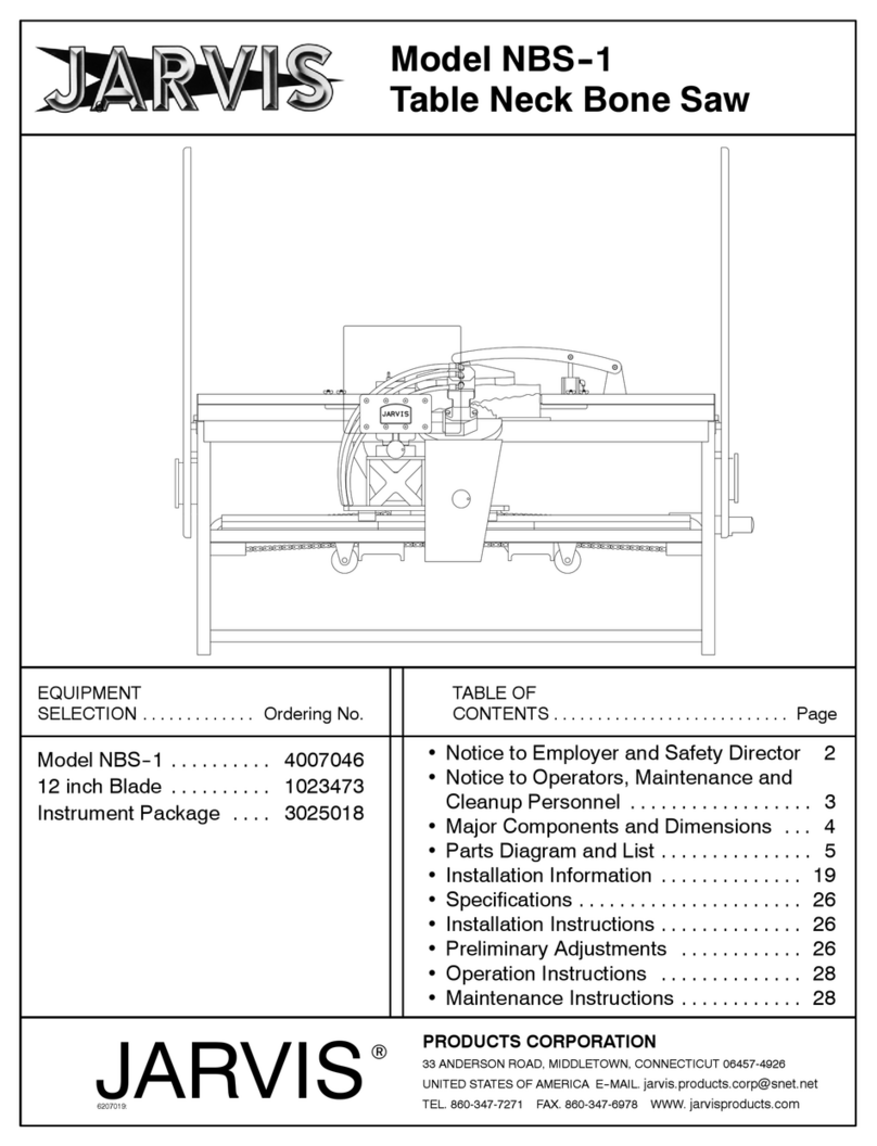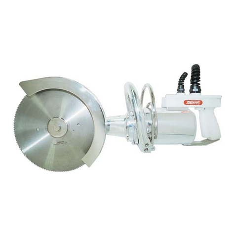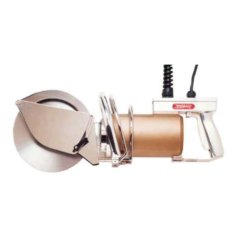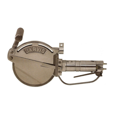
parts diagram and list
page 5 of 16 Model Buster IV
PRODUCTS CORPORATION
33 ANDERSON ROAD, MIDDLETOWN, CONNECTICUT 06457--4926
TEL. 860-347-7271 FAX. 860-347-6978 WWW.jarvisproducts.com
®
JARVIS
6206001;:
1 page 7 or 8 Top Handle Assembly 1
2 1013122 Internal Retaining Ring 1
3 1006025 Door Knob 1
4 1004051 Int. Tooth Lock Washer 1
5 1004093 Int. Tooth Lock Washer 1
6 1055304 Hex Head Screw 1
7 1055358 Hex Head Screw 1
8 page 7 Hanger Assembly 1
9 1055027 Socket Head Cap Screw 4
10 1026078 Driven Gear 60 Hz 86 Teeth 1
1026080 Driven Gear 50 Hz 82 Teeth
11 1002213 Bearing Retaining Cover 1
12 1021424 Ball Bearing 1
13 1044043 Bearing Retaining Flange 1
14 1035208 O-ring 1
15 1055331 Hex Head Screw 2
16 3063021 Conduit Assembly 1
17 1055498* Hex Head Screw 6
18 1004154 Plain Washer 6
19 1055344 Hex Head Screw 1
20 1050232 Male Elbow Assembly 1
21 1059030 Plastic Tubing (12 inch) 1
22 1050242 Male Connector 1
23 1055287 Hex Head Screw 2
24 1051001 Quick Connect Plug 1
25 1061203 External Water Manifold 1
26 1016233 Drive End Housing with
items 58 and 59 1
27 1011217 Drain Coupling 1
28 1055049 Socket Head Cap Screw 4
29 1004275 Washer 2
30 1055862 Flat Head Screw 2
31 1061614 Internal Water Manifold 1
32 1055499 Pan Head Screw 1
33 1061580 Adjustable Nozzle 1
34 1029187 Spacer 1
35 1035207 Oil Seal 1
36 1055338 Flat Head Socket Screw 5
37 1010214 Hinge Pin 1
38 1055296 Hex Head Screw 4
39 1004049 Split Lock Washer 4
40 1067007 Hinge with item 37 1
41 1002222 Drive Wheel Cover 1
42 1032156 Nut Cover Plate 1
43 1055277 Flat Head Socket Screw 1
44 1055459 Socket Head Cap Screw 2
45 1002209 Guide Plate Cover 1
46 1010579 Roll Pin 2
47 1032155 Guide Mounting Plate 1
48 1036127 Bushing (spare part only) 1
49 1061201 Door Catch 1
50 1007173** Bearing Locknut 1
51 1057022 Drive End Wheel 1
52 1055025 Flat Head Socket Screw 3
53 1002219 Drive End Rail Cover 1
54 1058061 Blade Guide 1
55 1055490 Pan Head Screw 3
56 1035210 O-ring 1
57 1055485 Flat Head Screw 1
58 1017081 Danger Label 1
59 1055482 Pan Head Screw 4
60 1061221 Saw Frame Rail 1
61 1002218 Idler End Rail Cover 1
62 1055361 Flat Head Socket Screw 3
63 page 6 Drive End Blade Guide 1
64 1024063 Blade Guide Guard 1
65 1055255 Flat Head Socket Screw 4
ITEM PART NO. PART NAME QTY
ITEM PART NO. QTY
DRIVE END
Figure B
PART NAME
*
**
** Tighten to 80 lbf--ft (109 N--m)
using wrench 8039120
* Tighten to 37 lbf--ft (50 N--m)

