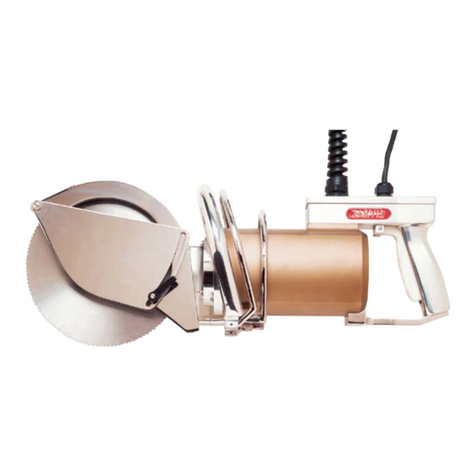
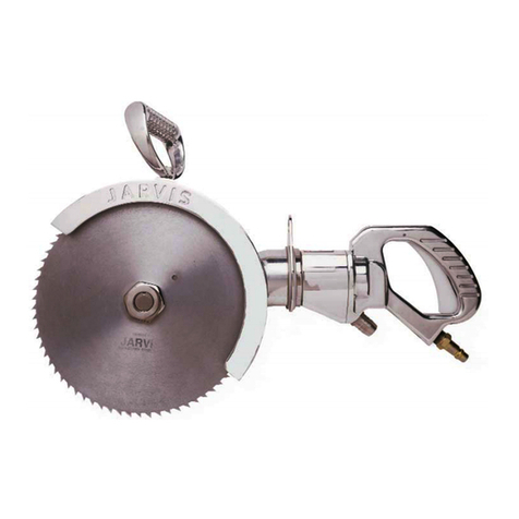
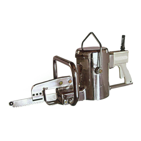
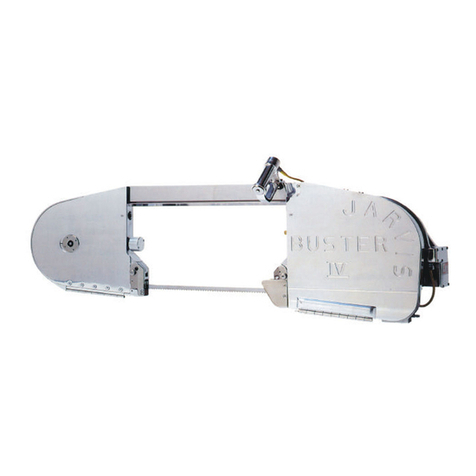
manuals.online logo
Brands
  1. Home
  2. •
  3. Brands
  4. •
  5. Jarvis
  6. •
  7. Saw
  8. •
  9. Jarvis SHC 140 User manual

Jarvis SHC 140 User manual

PRODUCTS CORPORATION
33 ANDERSON ROAD, MIDDLETOWN, CONNECTICUT 06457-4926
UNITED STATES OF AMERICA E--MAIL.
sales@ arvisproducts.com
TEL. 860-347-7271 FAX. 860-347-6978 WWW.
arvisproducts.com
TABLE OF
CONTENTS Page............................
ModelSHC140 4007028.............................
Model SHC 140 Ergonomic 4007052. . . . . . . . . . . . . . . . . . .
Model SHC 140 Left Handed 4007037. . . . . . . . . . . . . . . . . .
Model SHC 165 Standard 4007029. . . . . . . . . . . . . . . . . . . .
Model SHC 165 Ergonomic 4007053. . . . . . . . . . . . . . . . . . .
Model SHC 165 Left Handed 4007032. . . . . . . . . . . . . . . . . .
Model SHC 165B Brisket 4007036. . . . . . . . . . . . . . . . . . . . .
Model SHC 165G (16mm) 4007089. . . . . . . . . . . . . . . . . . . .
Model SHC 165G (13mm) 4007077. . . . . . . . . . . . . . . . . . . .
Model SHC 165GT (7 Blades) 4007087. . . . . . . . . . . . . . . . .
ModelSHC 205 4007075............................
Model SHC 205, Left Handed 4007076. . . . . . . . . . . . . . . . .
Hydr. Power Unit, Single Trigger, 575V/60Hz 4027283. . . .
Hydr. Power Unit, Single Trigger, 460V/60Hz 4027271. . . .
Hydr. Power Unit, Single Trigger, 440--220V/50Hz 4027274
Hydr. Power Unit, Dual Trigger, 460V/60Hz 4027273. . . . .
Hydr. Power Unit, Dual Trigger, 440--220V/50Hz 4027264.
Balancer SHC 140, 165, 165B and 205 4042033. . . . . . . . .
Balancer SHC 165G and 165GT 4042044. . . . . . . . . . . . . . .
Tool Kit 8039163....................................
Model SHC 140, 165, 165B, 165G,
165GT & 205 Hydraul c C rcular Saw
EQUIPMENT
SELECTION Ordering No.. . . . . . . . . . . . .

JARVIS
6207016::::.b
SHC 165
Left R ght
SHC 165B
SHC 165
ERGONOMIC
SHC 165G
SHC 165GT
US Patents: 6,511,483
6,805,696
European Patent: EP 0 890 313 B1
D
Safety Messages to Employer and Safety
Director 2.................................
D
Safety Messages to Operators, Maintenance
and Cleanup Personnel 3. . . . . . . . . . . . . . . . . . .
D
Parts Diagram and List 4. . . . . . . . . . . . . . . . . . . .
D
Installation Diagram 12. . . . . . . . . . . . . . . . . . . . .
D
Specifications 14. . . . . . . . . . . . . . . . . . . . . . . . . . .
D
Installation Instructions 14. . . . . . . . . . . . . . . . . . .
D
Operation Instructions 15. . . . . . . . . . . . . . . . . . . .
D
Maintenance Instructions 16. . . . . . . . . . . . . . . . .
safety messages to employer
and safety director
Model SHC 140, 165, 165B, 165G, 165GT and 205
page 2 of 20
PRODUCTS CORPORATION
33 ANDERSON ROAD, MIDDLETOWN, CONNECTICUT 06457-4926
UNITED STATES OF AMERICA E--MAIL.
sales@ arvisproducts.com
TEL. 860-347-7271 FAX. 860-347-6978 WWW.
arvisproducts.com

JARVIS
6207016::::.
1. Ensure that all employees who use this tool are trained in the proper use of this tool and are aware of
the dangers that may arise if they do not follow the procedures outlined in this brochure.
2. Enclosed are four (4) copies of “NOTICE TO OPERATORS, MAINTENANCE AND CLEANUP
PERSONNEL.” Post one copy on the employees’ bulletin board; give one copy to operator(s); give
one copy to the maintenance foreman; and give one copy to the sub-contract cleanup / internal cleanup
foreman. Additional copies will be provided upon request.
3. he tool is designed and intended to be powerful. his fact should be obvious to your employees, but
you must emphasize it to them.
4. Ensure that employees wear eye protection in accordance with OSHA’s eye and face protection re-
quirements 29 CFR 1910.133 while operating the tool.
5. Ensure that proper procedures are established in accordance with OSHA’s lockout/tagout procedures
29 CFR 1910.147 to prevent accidental startup or release of stored energy.
. Remove and repair any tool that malfunctions. All personnel must be instructed to remove any
malfunctioning equipment.
7. Never make modifications or alterations to the tool. Replace any missing or illegible labels.
8. Follow our installation and maintenance instructions for proper installation and care of the tool.
9. Avoid injury. Do not permit the tool to be misused.
10. If you resell or distribute a Jarvis product, you must provide the purchaser with the appropriate safety
sheets and tool brochure. Additional copies of safety sheets and tool brochures will be provided upon
request.
SAFETY MESSAGES TO EMPLOYER AND SAFETY DIRECTOR
AVOID INJURY
Keep hands clear.
safety messages to operators, maintenance
and cleanup personnel
Model SHC 140, 165, 165B, 165G, 165GT and 205
page 3 of 20
PRODUCTS CORPORATION
33 ANDERSON ROAD, MIDDLETOWN, CONNECTICUT 06457-4926
UNITED STATES OF AMERICA E--MAIL.
sales@ arvisproducts.com
TEL. 860-347-7271 FAX. 860-347-6978 WWW.
arvisproducts.com

JARVIS
6207016::::.
1. Disconnect all hydraulic and air hoses and shut the power off in accordance with OSHA’s lockout/
tagout procedures (29 CFR 1910.147) before making any blade changes.
2. Disconnect all hydraulic and air hoses and shut the power off OSHA’s lockout/tagout procedures (29
CFR 1910.147) before making any repair or performing any maintenance to the tool.
3. Disconnect all hydraulic and air hoses and shut the power off - or have the all hydraulic and air hoses
disconnected and the power shut off - in accordance with OSHA’s lockout/tagout procedures (29 CFR
1910.147) before performing any cleanup.
4. Disconnect all hydraulic and air hoses when the tool is not in use.
5. Always wear eye protection in accordance with OSHA’s eye and face protection requirements (29 CFR
1910.133) while operating the tool.
. Never put fingers, hands or other parts of the body on the cutting edge or within the cutting path of the
tool when it is connected to a power supply.
7. Always use both hands when starting and operating the tool to avoid the risk of possible “kick back”
or “recoil”. Continue holding the tool with both hands until the saw blade comes to a complete stop.
8. Test the tool prior to use daily. For single trigger tools: Depress the trigger and the tool should start.
Release the trigger and the tool should stop. For dual trigger tools: Depress one trigger, then pause
one second and depress the other trigger and the tool should not start. Repeat this procedure reversing
the triggers. Depress both triggers simultaneously and the tool should start. With the tool running,
release one trigger and the tool should stop. Continue holding the depressed trigger and then depress
the other trigger. he tool should not start. Repeat this procedure holding the other trigger. If the tool
malfunctions, remove it from service and report or repair it immediately.
9. Clean up any spilled or leaked hydraulic fluid.
10. Replace any worn or leaking hydraulic hoses or fittings.
11. Never depress the trigger(s) unless you want to use or test the tool.
12. Never make modifications or alterations to the tool. Replace any missing or illegible labels.
SAFETY MESSAGES TO OPERATORS, MAINTENANCE AND CLEANUP
PERSONNEL
REMOVE ANY MALFUNCTIONING TOOL FROM SERVICE
REPORT ANY PROBLEMS TO YOUR SUPERVISOR
Keep hands clear.
parts diagram and list
Model SHC 140, 165, 165B, 165G, 165GT and 205
page 4 of 20
PRODUCTS CORPORATION
33 ANDERSON ROAD, MIDDLETOWN, CONNECTICUT 06457-4926
UNITED STATES OF AMERICA E--MAIL.
sales@ arvisproducts.com
TEL. 860-347-7271 FAX. 860-347-6978 WWW.
arvisproducts.com

JARVIS
6207016::::.
1 1055905 Cheese Head Screw 1
2 1004020 Washer 1
3 3025010 Depth Gage Assy, RH 165 1
3025012 Depth Gage Assy, LH 165
3025015 Depth Gage Assy, RH 140
3025016 Depth Gage Assy, LH 140
4 1004001 Washer 1
5 1004021 Washer 1
6 1055954* Hex Head Screw 2
7 1036130* Auxiliary Handle Bushing 1
8 1019197* Auxiliary Handle, RH 1
1019198* Auxiliary Handle, LH
9 1024154 Blade Guard, RH 165 1
1024174 Blade Guard, LH 165
1024190 Blade Guard, RH 140
1024192 Blade Guard, LH 140
10 1054140 Blade Retaining Screw, RH 1
1054148 Blade Retaining Screw, LH
11 1004292 Blade Retaining Washer 1
12 1023324 Blade, 140 Teeth (165mm) 1
1023362 Blade, 120 Teeth (140mm)
1023308 Blade, 60 Teeth (165mm)
1023363 Blade, 60 Teeth (140mm)
13 1004293 Slinger 1
14 1035474 Oil Seal 1
15 1055899 Flat Head Screw 3
16 1002355 Gear Housing Cover, RH 1
1002373 Gear Housing Cover, LH 1
17 1021372 Ball Bearing 1
18 1026171 Crown Gear, RH 1
1026184 Crown Gear, LH
19 1021081 Ball Bearing 1
20 1038006 Grease Fitting 1
21 3016301 Gear Housing, RH 1
3016320 Gear Housing, LH
with items 20 and 22
3016304 Housing & Gear Assy, RH
3016319 Housing & Gear Assy, LH
(items 10, 11 and 13--27)
ITEM PART NO. PART NAME QTY
22 1021373 Needle Bearing 1
23 1026170 Pinion Gear, RH 1
1026183 Pinion Gear, LH
24 1021374 Bearing Race 1
25 1011300 Coupling 1
26 1021155 Ball Bearing 1
27 1013232 Internal Retaining Ring 1
28 1035164 O--ring 1
29 1032420 Adapter Plate, RH 1
1032453 Adapter Plate, LH
30 1042395 Hanger Bracket 1
31 1009153 Hanger Sleeve 1
32 1055742 Socket Head Cap Screw 4
33 3008172 Hydraulic Motor Assy, RH 1
3008189 Hydraulic Motor Assy, LH
(item 152, 157--160, 164--179)
34 1024155 Trigger Guard 1
35 1055725 Pan Head Screw 2
36 1032479GGuard Mounting Plate 1
37 1024023GBlade Guard (Brisket) 1
38 1055918GFlat Head Screw 1
39 1058153GBlade Guide (Brisket) 1
40 8039099 Blade Locking Pin 1
41 1019001 Straight Handle 1
42 1004003 Lock Washer 1
43 1055802 Hex Head Screw 1
44 1055835 Flat Head Screw 2
45 1033012 Depth Gage Index 1
46 1055901 Oval Head Screw 2
3024035 Guard & Gage Assy, RH 165
3024037 Guard & Gage Assy, LH 165
3024039 Guard & Gage Assy, RH 140
3024040 Guard & Gage Assy, LH 140
(items 1--5, 9, 45 and 46)
3024041 Guard Assembly (Brisket)
(items 36--39)
3019218* T--Handle Kit, RH (items 6--8)
3019217* T--Handle Kit, LH (items 6--8)
ITEM PART NO. PART NAME QTY
*
*
*
G
G
G
G
F gure A
SHC--140, 165 and 165B
a= 20 lbf--ft (27 Nm)
a
* optional -- must remove helical insert
in blade guard to install “T” handle.
** special tool 8039152 is available
GUsed on model SHC 165B brisket saw
**
parts diagram and list
Model SHC 140, 165, 165B, 165G, 165GT and 205
page 5 of 20
PRODUCTS CORPORATION
33 ANDERSON ROAD, MIDDLETOWN, CONNECTICUT 06457-4926
UNITED STATES OF AMERICA E--MAIL.
sales@ arvisproducts.com
TEL. 860-347-7271 FAX. 860-347-6978 WWW.
arvisproducts.com

JARVIS
6207016::::.
47 3025017 Depth Gage Assy, RH 1
3025021 Depth Gage Assy, LH
48 1024286 Blade Guard, RH 1
1024287 Blade Guard, LH
49 1023593 Blade, 76 Teeth (205 mm) 1
50 3016500 Right Hand Gear Housing 1
3016501 Left Hand Gear Housing
(with items 20 and 22)
51 1035005 O--ring 1
52 1032678 Adapter Plate, RH 1
1032679 Adapter Plate, LH
53 1073023 Flat Head Phillips Screw 1
54 1073024 Flat Head Phillips Screw 1
55 1073215 Flat Head Slotted Screw 2
56 1032494 Rub Plate 1
57 1029028 Spacer 2
58 1033017 Depth Gage Index 1
59 1024149 Trigger Guard 1
60 1055755 Hex Head Screw 2
61 1018131 Trigger Lever 1
62 1019224 Handle 1
63 1055157 Socket Head Cap Screw 4
64 1010286 Dowel Pin 1
65 1061966 Hydraulic Manifold w/item 73 1
66 1051082 Tube Connector 2
67 1073120 Socket Head Cap Screw 4
68 1051081 Plug 1
69 1035245 O--ring 1
70 1014086 Spring 1
71 1039034 Plunger Valve with item 72 1
ITEM PART NO. PART NAME QTY
F gure B
SHC 205
F gure C
SHC 165
Ergonom c Handle
ITEM PART NO. PART NAME QTY
72 1035279 O--ring 1
73 1021294 Bushing 1
74 1035479 O--ring 4
3019266 Ergonomic Handle Kit
(items 59--73 and 183)
3016530 Housing & Gear Assy, 205 RH
3016531 Housing & Gear Assy, 205 LH
(items 10, 11, 13--20, 22--27
and 50)
3024067 Guard & Gage Assy SHC205RH
3024068 Guard & Gage Assy SHC205LH
(items 2, 4, 5, 7, 47, 48, 53,
54, 56--58)
a
a= 20 lbf--ft (27 Nm)
parts diagram and list
Model SHC 140, 165, 165B, 165G, 165GT and 205
page 6 of 20
PRODUCTS CORPORATION
33 ANDERSON ROAD, MIDDLETOWN, CONNECTICUT 06457-4926
UNITED STATES OF AMERICA E--MAIL.
sales@ arvisproducts.com
TEL. 860-347-7271 FAX. 860-347-6978 WWW.
arvisproducts.com

JARVIS
6207016::::.
ITEM PART NO. PART NAME QTY
75 1055979 Hex Head Screw 4
76 1027078 Ad ustable Stud 4
77 1023536 Blade Scraper 2
3023190 Blade Scraper Kit (incls. 2
items 75 and 76, 1 item 77)
78 1055616 Cheese Head Screw 4
79 1055230 Hex Head Screw 5
80 1017081 Danger Label 1
81 1002519 Blade Guard Cover
with items 79 and 80
82 1054194 Blade Retaining Screw 1
83 1023550 Blade Insert Holder, 16 mm 1
1023549 Blade Insert Holder, 13 mm
84 1004421 Slinger 1
85 1035697 Seal 2
86 1055390 Flat Head Screw 4
87 1055395 Oval Head Screw 3
88 1024274 Blade Guard with item 89 1
89 1036206 Hanger Bushing 1
ITEM PART NO. PART NAME QTY
90 1021471 Ball Bearing 1
91 1026251 Crown Gear with item 93 1
92 1029420 Spacer 1
93 1010522 Dowel Pin 1
94 1021470 Ball Bearing 1
95 1014194 Wave Spring 1
96 1038027 Grease Fitting 1
97 1035064 O--ring 1
98 1054097 Plug with item 97 1
99 3016487 Gear Hd w/items 22, 96--98 1
100 1055377 Flat Head Screw 10
101 1023545 Blade Insert, 16 mm 10
1023535 Blade Insert, 13 mm 10
3023189 Blade Insert 10 pack, 16mm
3023193 Blade Insert 10 pack, 13mm
102 1007254 Lock Nut 10
103 1051118 Connector Elbow 1
104 1071480 Plastic Tubing, 15 ft 1
105 1023639 Blade Scraper 2
106 1002624 Cover 1
107 1073138 Blade Retaining Screw, 1
108 1004486 Internal Tooth Lock Washer 1
109 1004487 Blade Retaining Washer 1
110 1023363 Blade, 60 Teeth 7
111 1029492 Blade Stack Spacer 1
112 1026294 Crown Gear 1
3059032 Vacuum Hose Assy, 10 ft 1
3024066 Guard Assembly (items 14,
78--81, 88 and 89)
F gure D
SHC--165G
* Spanner wrench 8039093 is supplied
a= 20 lbf--ft (27 N--m)
b= 35 lbf--ft (47 N--m)
*
F gure E
SHC--165GT
a
b
parts diagram and list
Model SHC 140, 165, 165B, 165G, 165GT and 205
page 7 of 20
PRODUCTS CORPORATION
33 ANDERSON ROAD, MIDDLETOWN, CONNECTICUT 06457-4926
UNITED STATES OF AMERICA E--MAIL.
sales@ arvisproducts.com
TEL. 860-347-7271 FAX. 860-347-6978 WWW.
arvisproducts.com

JARVIS
6207016::::.
ITEM PART NO. PART NAME QTY
113 1055753 Hex Head Screw 1
114 1004304 Washer 1
115 1036334 Flanged Bushing 1
116 1071073 Hanger 1
117 1004431 Washer 1
118 1042559 Guard and Hanger Bracket 1
119 1029450 Spacer 1
120 1055132 Hex Head Screw 1
121 1032645 Adapter Plate 1
122 1061670 Blue Tubing, 2 feet 1
123 1061457 Yellow Tubing 6 feet 1
124 1051313 “Y” Fitting 1
125 1071150 Blue Tubing, 4 feet 1
126 1071226 Yellow Tubing, 8 feet 1
127 1051263 Elbow Fitting 2
128 1019256 Front Handle 1
F gure F
SHC--165G
SHC--165GT
ITEM PART NO. PART NAME QTY
129 1004230 Split Lock Washer 3
130 1055755 Hex Head Screw 3
131 1018132 Trigger Lever 1
132 1022211 3--Way Valve with item 136 1
133 1024191 Trigger Guard 1
134 1010577 Dowel Pin 2
135 1054153 Threaded Plug 1
136 1035012 O--ring 2
137 1055404 Hex Head Screw 2
138 1004262 Washer 2
139 1004361 Washer 2
140 1055055 Hex Head Screw 2
3019306 Handle Assembly (items 119,
120, and 127--136)
3019331 Dual Trigger ATD Kit (items
113--120, 122--135)
parts diagram and list
Model SHC 140, 165, 165B, 165G, 165GT and 205
page 8 of 20
PRODUCTS CORPORATION
33 ANDERSON ROAD, MIDDLETOWN, CONNECTICUT 06457-4926
UNITED STATES OF AMERICA E--MAIL.
sales@ arvisproducts.com
TEL. 860-347-7271 FAX. 860-347-6978 WWW.
arvisproducts.com

JARVIS
6207016::::.
141 1013233 Internal Retaining Ring 1
142 1035571 O--ring 1
143 1016570 Seal Housing 1
144 1035570 Oil Seal 1
145 1035308 O--ring 1
146 1061807 Seal Gland 1
147 1013180 Internal Retaining Ring 1
148 1020260 Drive Shaft 1
149 1021351 Ball Bearing 1
150 1013217 External Retaining Ring 1
151 3016302 Motor Front Hsg. Assy, RH 1
3016321 Motor Front Hsg. Assy, LH
(with items 153 and 159)
152 1035478 O--ring 2
153 1021362 Needle Bearing 4
154 1030065 Key 1
155 1020261 Idler Shaft 1
156 1026172 Gear 2
157 1032421 Motor Center Plate 1
158 1010390 Dowel Pin 2
159 1004347 Extraction Washer 3
160 1017083 Danger Label 1
161 3016303 Motor Rear Housing Assy 1
(with items 153 and 159)
162 1055902 Socket Head Cap Screw 4
163 1032422 Manifold Plate 1
164 3016515 Motor Rear Hsg Assy, RH 1
3016521 Motor Rear Hsg Assy, LH
(with items 159 and 165)
165 1021498 Needle Bearing 4
166 1026279 Gear 2
167 1020405 Idler Shaft 1
ITEM PART NO. PART NAME QTY
168 1030099 Key 1
169 3016516 Motor Front Hsg Assy, RH 1
3016517 Motor Front Hsg Assy, LH
(with items 159 and 165)
170 1004461 Seal Retaining Washer 1
171 1035689 Seal 1
172 1016707 Seal Housing 1
173 1035400 O--ring 1
174 1013197 Internal Retaining Ring 1
175 1020401 Drive Shaft 1
176 1021499 Ball Bearing 2
177 1013116 External Retaining Ring 1
178 1013317 Bearing Retaining Ring 1
179 1055903 Socket Head Cap Screw 4
180 1011087 Quick Connect Socket 1
181 1050602 Reducer Bushing 2
182 3059009 Hose Assy, 6 ft 2
183 1050230 Male Connector 2
184 1055904 Socket Head Cap Screw 4
185 1014086 Spring 1
186 1051081 Plug 1
187 1061636 Hydraulic Manifold with item 73 1
188 1018132 Trigger Lever 1
189 1061456 Blue Tubing, 6 feet 1
190 1011086 Quick Connect Plug 1
3022055 Air Switch Valve Assy (items 66,
69, 71--73, 134, 183 and 185--188)
3035058 Hyd Motor Seal Kit (old) (items
142--147 and 152)
3035093 Hyd Motor Seal Kit (new)(items
(152, 171--174 and 178)
ITEM PART NO. PART NAME QTY
c= 50 lbf--in (5.6 N--m)
c
F gure G
Hydraul c Motor
Assembly
3008172 Right Hand
3008189 Left Hand
c
Old Style
used before
Oct 2004
New Style
used after
Sept 2004
parts diagram and list
Model SHC 140, 165, 165B, 165G, 165GT and 205
page 9 of 20
PRODUCTS CORPORATION
33 ANDERSON ROAD, MIDDLETOWN, CONNECTICUT 06457-4926
UNITED STATES OF AMERICA E--MAIL.
sales@ arvisproducts.com
TEL. 860-347-7271 FAX. 860-347-6978 WWW.
arvisproducts.com

JARVIS
6207016::::.
F gure H
Hydraul c Power Un t w th “A”
Flanged Pump
4027271
1
pg 11 or 12
Control Box Assembly 1
2 1008193 Elec. Mtr., 460/230V--60Hz 1
1008197 Elec. Mtr., 440/400/230V,50Hz
1008196 Electric Motor, 575V--60Hz
3 1071429 Return Tubing Assembly 1
4 1061733 Tubing Assy, Filter to Sub plate 1
5 1042361 Mounting Bracket 1
6 1011324 Coupling Half, Motor 1
7 1011326 Coupling, Spider Center 1
8 1011325 Coupling Half, Pump 1
9 1071431 Tubing Assy, Pump to Filter 1
10 3034031 High Pressure Filter Assy 1
1034105 High Pressure Filter Element
11 3008650 Hydraulic Gear Pump 1
12 1050515 Adapter Elbow 1
13 1025008 Hydraulic Pressure Gage 1
14 1034013 Oil Breather Filler Cap 1
15 1034064 Triangular Filter Assembly 1
1034062 Filter Element only
ITEM PART NO. PART NAME QTY
16 1022043 Dir. Control Valve, 115V 1
1022172 Dir. Control Valve, 230V
1063843 din/iso Coil for Valve, 115V
1063844 din/iso Coil for Valve, 230V
17 1072135 din/iso Connector, 115V
1072136 din/iso Connector, 230V
18 1055376 Socket Head Cap Screw 4
19 1022120 Sub--Plate with item 20 1
20 1022119 Cartridge Relief Valve 1
21 1050462 Hex Nipple (4 inch) 1
22 1050126 Pipe Elbow 2
23 1050090 Hex Nipple (2 inch) 1
24 1025045 Oil Level Gage 1
25 1034007 Suction Strainer 1
26 1054166 Drain Plug with Magnet 1
27 1059003 Hydraulic Hose Assy, 16 ft 2
28 1011086 Quick Connect Plug 1
29 1011087 Quick Connect Socket 1
1017085 Electrical Danger Label 1
ITEM PART NO. PART NAME QTY
parts diagram and list
1 1008193 Elec. Mtr., 460/230V--60Hz 1
1008197 Elec. Mtr., 400/230V--50Hz
2 1042361 Mounting Bracket 1
3 1061734 Return Tubing Assembly 1
4 1011324 Coupling Half, Motor 1
5 1011326 Coupling, Spider Center 1
6 1011325 Coupling Half, Pump 1
7 3008113 Hydraulic Gear Pump 1
8 1050515 Adapter Elbow 1
9 1034064 Triangular Filter Assembly 1
1034062 Filter Element only
1034052* Square Filter Assembly
1034048* Filter Element only
10 1061733 Supply Tubing Assembly 1
11 1022043 Dir. Control Valve, 115V 1
1022172 Dir. Control Valve, 230V
1063072* Coil only for Valve, 115V
1063373* Coil only for Valve, 230V
1063843 din/iso Coil for Valve, 115V
ITEM PART NO. PART NAME QTY
1063844 din/iso Coil for Valve, 230V
1072135 din/iso Connector, 115V
1072136 din/iso Connector, 230V
12 1055376 Socket Head Cap Screw 4
13 pg 10 or 11 Control Box Assembly 1
14 1022120 Sub--Plate with item 18 1
15 1050462 Hex Nipple (4 inch) 1
16 1050090 Hex Nipple (2 inch) 1
17 1050126 Pipe Elbow 2
18 1022119 Cartridge Relief Valve 1
19 1025045 Oil Level Gage 1
20 1059003 Hyd. Hose Assembly, 16 ft 2
21 1034007 Suction Strainer 1
22 1054166 Drain Plug with Magnet 1
23 1011086 Quick Connect Plug 1
24 1011087 Quick Connect Socket 1
25 1034013 Oil Breather Filler Cap 1
26 1025008 Hydraulic Pressure Gage 1
27 1050508 Hex Nipple, 1.5 inch 1
28 1050753 Reducer Bushing 1
29 1050127 Pipe Tee 1
30 1050668 Male Elbow 3
1017085 Electrical Danger Label 1
ITEM PART NO. PART NAME QTY
* not used in current units
F gure I
4027115
Hydraul c
Power Un t w th “AA”
Flanged Pump
Model SHC 140, 165, 165B, 165G, 165GT and 205
page 10 of 20
PRODUCTS CORPORATION
33 ANDERSON ROAD, MIDDLETOWN, CONNECTICUT 06457-4926
UNITED STATES OF AMERICA E--MAIL.
sales@ arvisproducts.com
TEL. 860-347-7271 FAX. 860-347-6978 WWW.
arvisproducts.com

JARVIS
6207016::::.
parts diagram and list
Model SHC 140, 165, 165B, 165G, 165GT and 205
page 11 of 20
PRODUCTS CORPORATION
33 ANDERSON ROAD, MIDDLETOWN, CONNECTICUT 06457-4926
UNITED STATES OF AMERICA E--MAIL.
sales@ arvisproducts.com
TEL. 860-347-7271 FAX. 860-347-6978 WWW.
arvisproducts.com

JARVIS
6207016::::.
1 1032266 Mounting Plate 1
2 1063083 Wire Ring Terminal 8
3 1055477 Hex Head Screw 2
4 1004244 Internal Tooth Lock Washer 2
5 1055398 Socket Head Cap Screw 2
6 1004206 Washer 4
7 1007355 Hex Lock Nut 2
8 1051062 Reducer Bushing, Pipe 1
9 1050300 Square Head Plug 2
10 1051082 Tube Connector 2
11 1061458 Blue Tubing, 16 feet 1
12 1051119 Tube to Tube Connector 2
13 1050027 Street Elbow 1
14 1051001 Quick Connect Plug 1
15 1034014 Air Filter/Regulator 1
16 1051063 Street Tee 1
17 1004154 Washer 1
18 1051069 Hex Head Bleed Fitting 1
19 1061459 Yellow Tubing, 16 feet 1
20 1051065 Actuator 1
21 1005059 Push Button Switch 1
22 1016347 Control Box Enclosure 1
23 1063011 Electrical Relay 1
24 1063079 Wire Ring Terminal 2
25 1017085 Electrical Danger Label 1
ITEM PART NO. PART NAME QTY
F gure J
Control Box Assembly
S ngle Tr gger Tools Dual Tr gger Tools
26 1017113 Wiring Diagram Label, 115V 1
1017160 Wiring Diagram Label, 230V
27 1007278 Locking Nut 2
28 1004211 Sealing Washer 2
29 1001295 Electric Cord, 4 feet 1
30 1011240 Strain Relief Connector 2
31 1063238 Electrical Enclosure Plug 2
32 1051211 Tube to Pipe Connector 1
33 1061347 Black Tubing, 20 feet 1
34 1051124 Tube to Pipe Connector 2
35 1072091 Fuse 1
36 1063502 Wire Fork Terminal 13
37 1017320 Wiring Diagram Label, 115V 1
1017321 Wiring Diagram Label, 230V
38 1072071 ATD Circuit Board, 115V
1072072 ATD Circuit Board, 230V
39 1029445 Hex Spacer 4
40 1073072 Plastic Slotted Head Screw 4
Single Trigger:
3016192 Control Box Assy, 115V
3016219 Control Box Assy, 230V
Dual Trigger:
3063282 Control Box Assy, 115V
3063362 Control Box Assy, 230V
ITEM PART NO. PART NAME QTY
installation diagram
Model SHC 140, 165, 165B, 165G, 165GT and 205
page 12 of 20
PRODUCTS CORPORATION
33 ANDERSON ROAD, MIDDLETOWN, CONNECTICUT 06457-4926
UNITED STATES OF AMERICA E--MAIL.
sales@ arvisproducts.com
TEL. 860-347-7271 FAX. 860-347-6978 WWW.
arvisproducts.com

JARVIS
6207016::::.
F gure 1
Hose Connect on D agram
S ngle Tr gger
Control Box Assembly
(Factory Installed on Hydraulic Power Unit)
Control Box
Assembly
Hydraulic
Power Unit
Blue
Tubing
Yellow
Tubing
Pressure
Line
Return
Line
Street
Tee
Air
Supply
Inlet
Air
Filter/Reg
installation diagram
Model SHC 140, 165, 165B, 165G, 165GT and 205
page 13 of 20
PRODUCTS CORPORATION
33 ANDERSON ROAD, MIDDLETOWN, CONNECTICUT 06457-4926
UNITED STATES OF AMERICA E--MAIL.
sales@ arvisproducts.com
TEL. 860-347-7271 FAX. 860-347-6978 WWW.
arvisproducts.com

JARVIS
6207016::::.
F gure 2
Hose Connect on D agram
Dual Tr ggers
Control Box Assembly
(Factory Installed on
Hydraulic Power Unit)
Control Box
Assembly
Hydraulic
Power Unit
Yellow
Tubing
Pressure
Line
Return
Line
Street
Tee
Air
Supply
Inlet
Air
Filter/Reg
Black
Tubing
Return Signals
from Handles
(Yellow)
Supply Air
to Handles
(Blue)
specifications and
installation instructions
Model SHC 140, 165, 165B, 165G, 165GT and 205
page 14 of 20
PRODUCTS CORPORATION
33 ANDERSON ROAD, MIDDLETOWN, CONNECTICUT 06457-4926
UNITED STATES OF AMERICA E--MAIL.
sales@ arvisproducts.com
TEL. 860-347-7271 FAX. 860-347-6978 WWW.
arvisproducts.com

JARVIS
6207016::::.
SPECIFICATIONS
All Models
Motor Power 2.5 hp 1865 W
Blade Speed at 3.5 gal/min 2725 rpm
Vibration less than (<) 100 dB < 0.1 m/sec
2
Noise (one meter from tool) 87 dB
Model SHC 140, 1 5 and 205
Control Handle Single trigger / Pneumatic
Blade Diameter 8.1 in 205 mm
6.5 in 165 mm
5.5 in 140 mm
Cutting Depth 2.8 in 71.0 mm
2.0 in 50.8 mm
1.5 in 38.1 mm
Overall Length 16.5 in 419 mm
Weight 7 lbs 3.2 kg
Model SHC 1 5G and 1 5GT
Control Handle Dual Anti-- ie Down / Pneumatic
Cutter Head Width Pork 0.51 in 13 mm
Beef 0.63 in 16 mm
Cutting Depth Pork 0.81 in 20.6 mm
Beef 0.88 in 22.4 mm
Overall Length 15 in 381 mm
Weight 8.6 lbs 3.9 kg
Hydraulic Power Unit
Motor Power 5 hp 3728 W
Operating Voltage all voltages and 50 Hz. available
Hose Length 16 ft 5 m
Oil Capacity 20 gal 76 L
Oil Visc. at 100°F/40°C 200 SUS 46 ISO
Oil Flow Rate 3.5 gal/min 13.2 L/min
Overall Dimensions (l x w x h) 28 x 23 x 28 in
711 x 584 x 711 mm
Weight (without oil) 225 lbs 102 kg
INSTALLATION INSTRUCTIONS
ALWAYS DISCONNECT THE POWER SUPPLY IN
ACCORDANCE WITH OSHA’S LOCKOUT/TAGOUT
PROCEDURES (29 CFR 1910.1 7) BEFORE PERFORM-
ING ANY REPAIRS OR MAINTENANCE.
ALL WIRING MUST BE DONE IN ACCORDANCE WITH
NATIONAL, STATE AND LOCAL ELECTRICAL CODES.
Refer to Figure 1 or 2 on page 12 or 1 as a guide for con-
necting the air and hydraulic hoses.
1 Install the SHC saw above the work station from a
balancer. Jarvis part number 4042033 or 4042044
is available.
1.1 he SHC saw should have enough travel to al-
low the operator to reach the entire work area.
2 Install the hydraulic power unit overhead or on the
floor behind the work station.
2.1 Avoid excessive height and long pipe runs.
3 Wire the power unit. Refer to the wiring diagram la-
bel inside the control box cover (item 37, Figure J,
page 11) for the correct operating voltage and fre-
quency.
4 Equip the power unit with a master pilot light switch
at the operators station. This will facilitate shut-
down in case of an equipment failure.
5 Fill the oil reservoir with a USDA approved pre-
mium grade hydraulic fluid (viscosity: 200 SUS at
100°F / 46 ISO at 40°C).
6 Make all necessary air hose connections.
Single Trigger Tools: Refer to Figure J, page 11.
6.1 For the air supply line: use tube to tube connec-
tor (item 12) to connect blue plastic tubing (item
11) from air filter / regulator (item 15) to blue
plastic tubing (item 189, Figure G, page 8) from
the port marked “IN” on hydraulic manifold
(item 187, Figure G, page 8 or item 65, Figure
B, page 5).
6.2 For the air return line: use tube to tube connector
(item 12) to connect yellow plastic tubing (item
19) from tube connector (item 10) to yellow
plastic tubing (item 123, Figure F, page 7) from
the port marked “OU ” on hydraulic manifold
(item 187, Figure G, page 8 or item 65, Figure
B, page 5).
installation and
operation instructions
Model SHC 140, 165, 165B, 165G, 165GT and 205
page 15 of 20
PRODUCTS CORPORATION
33 ANDERSON ROAD, MIDDLETOWN, CONNECTICUT 06457-4926
UNITED STATES OF AMERICA E--MAIL.
sales@ arvisproducts.com
TEL. 860-347-7271 FAX. 860-347-6978 WWW.
arvisproducts.com

JARVIS
6207016::::.
Dual Trigger Tools: Refer to Figure J, page 11.
6.3 For the air supply line: use “Y” fitting (item 124,
Figure F, page 7) to connect black plastic tubing
(item 33) from air filter / regulator (item 15) to
blue plastic tubing (item 122, Figure F, page 7)
from the port marked “IN” on hydraulic man-
ifold (item 187, Figure G, page 8), and to blue
plastic tubing (item 125, Figure F, page 7) from
elbow fitting (item 127, Figure F, page 7) closest
to gear head (item 99, Figure D, page 6).
6.4 For the air return line: use tube to tube connec-
tors (item 34) to connect yellow plastic tubing
(item 19) from tube to pipe connectors (item 34)
to yellow plastic tubing (item 126, Figure F,
page 7) from the port marked “OU ” on hydrau-
lic manifold (item 187, Figure G, page 8), and to
yellow plastic tubing, (item 123, Figure F, page
7) from elbow fitting (item 127, Figure F, page
7) furthest from gear head (item 99, Figure D,
page 6.
For Single and Dual Trigger Tools: Refer to Figure H,
page 9 unless noted otherwise.
7 Make all necessary hydraulic hose connections.
7.1 Connect the quick connect socket (item 29) of
the supply line marked “A” on the hydraulic
power unit to the quick connect plug (item 190,
Figure G, page 8) connected to the hydraulic
manifold port marked “IN.”
7.2 Connect the quick connect plug (item 28) of the
return line marked “B” on the hydraulic power
unit to the quick connect socket (item 180, Fig-
ure G, page 8) connected to the hydraulic man-
ifold port marked “OU .”
8 Note: here are no adjustments to be made at the hy-
draulic power unit for blade speed or hydraulic pres-
sure. he blade speed is a result of using the full out-
put of the pump and cannot be increased. he pump
is set to a maximum relief pressure of 2000 psi. Dur-
ing operation, the pressure gage (item 13, Figure H,
page 9) will only show the pressure required to make
the cut. he pressure gage should read approximate-
ly 300 psi with the saw running under no load.
OPERATION INSTRUCTIONS
ALWAYS DISCONNECT ALL HYDRAULIC AND AIR
HOSES AND SHUT OFF THE POWER SUPPLY IN
ACCORDANCE WITH OSHA’S LOCKOUT/TAGOUT
PROCEDURES (29 CFR 1910.1 7) BEFORE PERFORM-
ING ANY REPAIRS OR MAINTENANCE.
1 urn on the power.
2Prior to use or daily, perform the following tests:
For Single Trigger Tools:
2.1 Make sure that the trigger lever (item 188, Fig-
ure G, page 8) is working correctly. Depress the
trigger and the tool should start. Release the
trigger and the tool should stop. If the tool mal-
functions, remove it from service and report the
problem to your supervisor immediately.
Always use two hands when starting and
stopping the tool. Continue holding the tool
with two hands until the saw blade comes to
a complete stop.
For Dual Trigger Tools:
2.2 Make sure that the dual anti--tie down control
triggers on the side and rear handles are working
correctly. Depress each trigger separately and
the tool should not start. Depress one trigger,
then pause one second and depressthe other trig-
ger and the tool should not start. Repeat this pro-
cedure reversing the triggers. Depress both trig-
gers simultaneously (within one half second of
each other) and the tool should start. With the
tool running, release one trigger and the tool
should stop. Continue holding the depressed
trigger and then depress the other trigger. he
tool should not start. Repeat this procedure
holding the other trigger. If the tool malfunc-
tions, remove it from service and report the
problem to your supervisor immediately.
Always use two hands when starting and
stopping the tool. Continue holding the tool
with two hands until the saw blade comes to
a complete stop.
2.3 Make sure the SHC saw moves freely on the ba-
lancer.
3 Making the cut.
3.1 Position the SHC saw.
3.2 Depress the trigger fully to start the motor and
make the cut.
Always use two hands when starting the tool
and while making the cut.
operation and
maintenance instructions
Model SHC 140, 165, 165B, 165G, 165GT and 205
page 16 of 20
PRODUCTS CORPORATION
33 ANDERSON ROAD, MIDDLETOWN, CONNECTICUT 06457-4926
UNITED STATES OF AMERICA E--MAIL.
sales@ arvisproducts.com
TEL. 860-347-7271 FAX. 860-347-6978 WWW.
arvisproducts.com

JARVIS
6207016::::.
3.3 When the desired length of cut is reached, re-
lease the trigger. his will stop the blade from
rotating.
Continue holding the tool with two hands un-
til the saw blade comes to a complete stop.
3.4 Withdraw the saw blade from the carcass.
Note: Avoid banging the blade into bone, as this could
damage the saw due to the cutting power available. All
cuts should be made in a firm, steady motion with the car-
cass supported to prevent it from moving with the pres-
sure of the blade.
MAINTENANCE INSTRUCTIONS
ALWAYS DISCONNECT ALL HYDRAULIC AND AIR
HOSES AND SHUT OFF THE POWER SUPPLY IN AC-
CORDANCE WITH OSHA’S LOCKOUT/TAGOUT PRO-
CEDURES (29 CFR 1910.1 7) BEFORE PERFORMING
ANY REPAIRS OR MAINTENANCE
.
Refer to Figures A to G on pages 4--8 for referenced
items.
1 DAILY:
Note: The hydraulic and air hoses must be
connected and the power turned on to per-
form the above maintenance check only.
For Single Trigger Tools:
1.1 Make sure that the trigger lever (item 188) is
working correctly. Depress the trigger and the
tool should start. Release the trigger and the tool
should stop. If the tool malfunctions, repair or
remove it from service immediately.
For Dual Trigger Tools:
1.2 Make sure that the dual anti--tie down control
triggers on the side and rear handles are working
correctly. Depress each trigger separately and
the tool should not start. Depress one trigger,
then pause one second and depressthe other trig-
ger and the tool should not start. Repeat this pro-
cedure reversing the triggers. Depress both trig-
gers simultaneously (within one half second of
each other) and the tool should start. With the
tool running, release one trigger and the tool
should stop. Continue holding the depressed
trigger and then depress the other trigger. he
tool should not start. Repeat this procedure
holding the other trigger. If the tool malfunc-
tions, remove it from service and report the
problem to your supervisor immediately.
Always use two hands when starting and
stopping the tool. Continue holding the tool
with two hands until the saw blade comes to
a complete stop.
1.3 Four (4) times per day, add Jarvis 1 15 White
Grease to the grease fitting (item 20 or 96) in the
gear housing (item 21, 50 or 99).
1.4 Check the level of the hydraulic fluid in the pow-
er unit.
1.5 Inspect all hoses for leaks, cuts and abrasions
and replace if necessary.
1.6 Check all fittings for leaks and tighten or re-
place, as necessary.
2 WEEKLY:
2.1 Check the condition of the fluid in the hydraulic
power unit. Replace the fluid if it appears dirty
or smells burnt. Always replace the filters
(items 10 and 15, Figure H, page 9) when chang-
ing the fluid.
3 BLADE REMOVAL:
SHC--140, 165, 165B and 205 Models
3.1 Loosen or remove (SHC--165B) flat head
screws (item 44 or 55) and pivot the blade guard
and gage assembly (item 9, 37 or 48) up and
away from the blade.
3.2 Remove the blade retaining screw (item 10) and
blade retaining washer (item 11) and remove
blade (item 12 or 49).
3.2.1 Place blade locking pin (item 40) through
the hole in the blade to prevent it from rotat-
ing.
3.3 Inspect all parts for wear and replace, as neces-
sary.
3.3.1 Sharpen or replace the blade, as necessary.
SHC--165G Model
3.4 Remove hex head screws (item 79) and separate
cover assembly (items 75--81, 103 and 104)
from blade guard (item 88).
3.5 Remove the blade retaining screw (item 82) us-
ing adjustable spanner wrench (8039093).
maintenance instructions
Model SHC 140, 165, 165B, 165G, 165GT and 205
page 17 of 20
PRODUCTS CORPORATION
33 ANDERSON ROAD, MIDDLETOWN, CONNECTICUT 06457-4926
UNITED STATES OF AMERICA E--MAIL.
sales@ arvisproducts.com
TEL. 860-347-7271 FAX. 860-347-6978 WWW.
arvisproducts.com

JARVIS
6207016::::.
3.6 Remove blade insert holder (item 83) with blade
inserts (item 101) and slinger (item 84) still at-
tached.
3.7 Inspect all parts for wear and replace, as neces-
sary.
3.7.1 Remove and replace the blade inserts (item
101), as necessary.
SHC--165G Model
3.8 Remove hex head screws (item 79) and separate
cover assembly (items 75--80, 103--106) from
blade guard (item 88).
3.9 Remove the blade retaining screw (item 107),
lock washer (item 108), and blade retaining
washer (item 109). Remove blades (item 110).
3.9.1 Place blade locking pin (item 40) through
the hole in the blades to prevent them from
rotating.
4 BLADE INS ALLA ION:
4.1 Reverse steps and procedures outlined in section
3. Refer to Figure below as a guide for instal-
ling blade.
4.1.1 o ensure proper fit and safe operation, the
slinger (item 13 or 84) and saw blade (item
12, 49 or 110) or blade insert holder (item
83) must fit securely on the lip of crown gear
(item 18, 91 or 112).
4.1.2 he teeth or blade inserts at the bottom of
the blade or blade insert holder should point
toward the operator and rotate counter--
clockwise.
F gure 3
Blade Installat on
Saw Blade
Rotation Direction
Crown Gear
Slinger
Blade
Hex
Screw
Blade Retaining
Washer
Lip
5 BLADE SCRAPER REMOVAL: (SHC--165G and
SHC--165G )
5.1 Remove hex head screws (item 75), adjustable
studs (item 76) and blade scraper (item 77 or
105).
5.2 Inspect all parts for wear and replace, as neces-
sary.
6 BLADE SCRAPER ASSEMBLY: (SHC--165G)
6.1 Reverse step 5.1.
6.2 With hex screws (item 75) only finger tight, ro-
tate adjustable studs (item 76) until blade scrap-
er (item 105) just contacts the blade inserts (item
101) on the blade insert holder (item 83). Back
off the adjustable studs (item 76)
1
/
16
th of a turn.
ighten hex screws (item 75).
7 GEAR HOUSING DISASSEMBLY:
7.1 Remove blade and blade guard as outlined in
section 3.
7.2 Remove the two screws (item 32) and separate
the gear head assembly from the hydraulic mo-
tor assembly. Set motor assembly aside.
7.3 Remove the slinger (item 13 or 84) from the lip
of gear housing cover (item 16) or blade guard
(item 88).
7.4 Remove the three screws (item 15 or 87) and re-
move the gear housing cover (item 16) or blade
guard (item 88).
7.5 Lightly tap the gear housing (item 21, 50 or 99)
with a nylon mallet in the vicinity of the guard
mounting flange to dislodge the crown gear and
bearings (items 17--19 or 90--95).
7.6 Disassemble the crown gear.
7.6.1 Press the ball bearing (item 17 or 90) from
the crown gear (item 18 or 91).
7.6.2 urn crown gear around and press the ball
bearing (item 19 or 94) from shaft of crown
gear.
7.7 Remove the internal retaining ring (item 27)
from the gear housing (item 21, 50 or 99).
7.8 Lightly tap the gear housing (item 21, 50 or 99)
with a nylon mallet in the vicinity of the guard
mounting flange to dislodge the pinion gear as-
sembly (items 23--26).
maintenance instructions
Model SHC 140, 165, 165B, 165G, 165GT and 205
page 18 of 20
PRODUCTS CORPORATION
33 ANDERSON ROAD, MIDDLETOWN, CONNECTICUT 06457-4926
UNITED STATES OF AMERICA E--MAIL.
sales@ arvisproducts.com
TEL. 860-347-7271 FAX. 860-347-6978 WWW.
arvisproducts.com

JARVIS
6207016::::.
7.9 Disassemble the pinion gear.
7.9.1 Press the ball bearing (item 26) from the
coupling (item 25).
7.9.2 Press the coupling (item 25) from the pinion
gear (item 23).
7.10 Remove bearing race (item 24), if necessary.
7.11 Inspect all parts for wear and replace as neces-
sary.
F gure 4
Spec al Tools
8039139
Needle Bearing
Extraction Tool
8039140 or
8039152
Needle Bearing
Extraction and
Installation Tool
8039118
Needle Bearing
Extraction Tool
THE ABOVE TOOLS ARE RECOMMENDED FOR
PROPER AND EFFECTIVE ASSEMBLY AND DIS-
ASSEMBLY OF THE JARVIS MODEL SHC 140, 165,
165B, 165G AND 205 HYDRAULIC CIRCULAR
SAWS.
8039163 Complete
Tool K t
8 GEAR HOUSING ASSEMBLY:
8.1 Reverse procedure outlined in section 7. See
special notes below.
8.1.1 Jarvis assembly tool 8039152 is available
for the installation of needle bearing (item
22). See Figure 4. Always press on the lip
that has the manufacturer’s markings. Note:
Pressing the unmarked (and unhardened)
lip will deform and damage the bearing.
8.1.2 When installing internal retaining ring (item
27), make sure that the beveled edge faces
away from gear housing (item 21, 50 or 99).
See Figure 5 below.
Retaining
Ring
Gear Housing
Note Bevel
Direction
F gure 5
Reta n ng R ng
Installat on
9 Remember to install wave spring (item 95) in gear
head (item 99) before crown gear assembly (items
90--94).
10 DRIVE SHAF SEAL REPLACEMEN -- Old
Style:
Note: It is not necessary to disassemble the hydraulic
motor to replace the old style drive shaft seal. All compo-
nents of shaft seal cartridge (items 142--147) must be re-
placed with hydraulic motor seal kit, 0 5058.
10.1 Separate the gear housing (item 21, 50 or 99) and
motor assembly as outlined in section 7, steps
7.1--7.3.
10.2 Remove the two screws (item 32) and remove
motor adapter plate (item 29, 52 or 121).
10.3 Remove the internal retaining ring (item 141)
and use the lip on the seal housing (item 143) to
gently lift the seal cartridge (item 142--147)
from the motor.
10.4 Inspect the drive shaft (item 148) for wear or
galling. If the shaft is only polished, proceed to
step 10.5. If shaft needs replacing, refer to sec-
tions 11 and 12.
10.5 Remove the internal retaining ring (item 147).
10.6 Lubricate the new seal (item 144) with Jarvis
1 15 White Grease and install it in new seal
gland (item 146).
maintenance instructions
Model SHC 140, 165, 165B, 165G, 165GT and 205
page 19 of 20
PRODUCTS CORPORATION
33 ANDERSON ROAD, MIDDLETOWN, CONNECTICUT 06457-4926
UNITED STATES OF AMERICA E--MAIL.
sales@ arvisproducts.com
TEL. 860-347-7271 FAX. 860-347-6978 WWW.
arvisproducts.com

JARVIS
6207016::::.
10.7 Replace the o--rings (items 142 and 145) with
new ones from seal kit and apply a liberal coat
of Jarvis 1 15 White Grease to the o--rings and
drive shaft.
10.8 Install internal retaining ring (item 147).
10.9 Install new seal cartridge (items 142--147) and
internal retaining ring (item 141) into the motor.
10.10 Reassemble the motor to the gear housing, re-
versing procedures outlined in section 7, steps
7.1--7.3.
11 DRIVE SHAF SEAL REPLACEMEN -- New
Style:
Note: Hydraulic repair kit 0 509 should be available
before disassembling motor.
11.1 Disassemble motor as described in section 12,
steps 12.1--12.8.
11.2 Remove bearing retaining ring (item 178).
11.3 Slide drive shaft (item 175) with ball bearings
(items 176) from motor front housing (item
169).
11.4 Remove external retaining ring (item 177) and
ball bearings (item 176) from drive shaft (item
175). Inspect and replace if necessary.
11.5 Remove internal retaining ring (item 174).
11.6 Remove seal housing (item 172) with o--ring
(item 173), seal (item 171) and seal retaining
washer (item 170).
11.7 Discard items 152, 171--174 and 178. Replace-
ments are included in repair kit 3035093.
11.8 Reassemble o--ring (item 173) onto seal hous-
ing (item 172).
11.9 Assemble internal retaining ring (item 174), seal
housing (item 172) with o--ring (item 173), seal
(item 171) and seal retaining washer (item 170)
onto drive shaft (item 175).
11.10 Apply a liberal coat of Jarvis 1 15 White
Grease to all seals, o--rings and drive shaft.
11.11 Gently insert drive shaft and components as-
sembled above into motor front housing (item
169).
11.12 Insert external retaining ring (item 174) into
groove in motor front housing (item 169).
11.13 Reinstall ball bearings (items 176), external re-
taining ring (item 177) and bearing retaining
ring (item 178).
11.14 Reassemble the motor to the gear housing, re-
versing procedures outlined in section 7, steps
7.1--7.3.
12 HYDRAULIC MO OR DISASSEMBLY:
Note: Cleanliness of the maintenance work area should
be maintained whenever performing any work on the
tool. Due to the exacting nature of the tolerances in a hy-
draulic motor, extra vigilance must be observed. Even
a small amount of foreign matter can cause immediate
failure, or seriously degrade the motor’s performance
and shorten its life. Inspect all parts for dirt or dust prior
to installation and keep them covered with a lint--free
cloth when not working on them.
Note: Never place the motor or any of its components in
a vise. Deformation will occur.
Old and New Style Motors
12.1 Separate the gear housing (item 21, 50 or 99) and
motor assembly as outlined in section 7, steps
7.1--7.3.
12.2 Remove the two screws (item 32) and remove
the motor adapter plate (item 29, 52 or 121).
12.3 Remove the four screws (item 67 or 184) and re-
move the hydraulic manifold assembly (items
59--65 or 71--73, 134 and 185--188).
12.4 Remove the four screws (item 179) and separate
the manifold plate (item 163) from the motor.
12.5 Remove the four screws (item 162).
12.6 Gently pull the rear motor housing (item 161 or
164) from the motor.
12.7 Gently remove the motor center plate (item
157). Be careful not to scratch the bores of the
center plate on the hydraulic gear teeth.
12.8 Remove the two gears (item 156 or 166), the key
(item 154 or 168) and idler shaft (item 155 or
167).
Old Style Motor
12.9 Remove and disassemble the seal cartridge as
outlined in section 10, step 10.3--10.5.
12.10 Remove the drive shaft and bearing assembly
(items 148--150). Remove the retaining ring
(item 150) from the drive shaft (item 148) and
press the drive shaft from the bearing (item 149).
maintenance instructions
Model SHC 140, 165, 165B, 165G, 165GT and 205
page 20 of 20
PRODUCTS CORPORATION
33 ANDERSON ROAD, MIDDLETOWN, CONNECTICUT 06457-4926
UNITED STATES OF AMERICA E--MAIL.
sales@ arvisproducts.com
TEL. 860-347-7271 FAX. 860-347-6978 WWW.
arvisproducts.com

JARVIS
6207016::::.
New Style Motor
12.11 Disassemble motor as described in section 11,
steps 11.2 -- 11.7.
Old and New Style Motors
Note: The motor O--rings (item 152) will acquire a per-
manent set in their cross section after they have been in
service. This will reduce their effectiveness upon re--use.
The motor o--rings should always be replaced whenever
the motor is disassembled.
12.12 Remove the two o--rings (item 152) from their
respective housings and discard.
12.13 Remove the needle bearings (item 153 or 165)
from the front and rear motor housings (items
151 or 169 and 161 or 164). Jarvis tool 8039139
is available. See Figure 6 below.
12.13.1 Insert the 5 mm screw (1055993) and nut
(1007243) through the bearing extraction
tool and into the bearing extraction washer
(item 159). Restrain the screw from rotating
while turning the nut clockwise to remove
the bearing from the bore. See Figure 6 be-
low.
F gure 6
12.13.2 he needle bearing for drive shaft (item 148
or 175) can be pressed out through the gear
head side of the front motor housing (item
151 or 169). Jarvis tool 8039140 is avail-
able. See Figure 4 on page 18.
12.14 Inspect all parts for wear and replace as neces-
sary. ake special note of the condition of the
bores in the motor center plate (item 157), the
needle bearing journals on drive shaft (item 148
or 175) and idler shaft (item 155 or 167), and the
square key (item 154 or 168).
12.15 Inspect the ground faces of the front and rear
motor housings (items 151 or 169 and 161 or
164), center plate (item 157), manifold plate
(item 163) and hydraulic manifold (item 65 or
187) for nicks or burrs. Small burrs may be re-
moved by lightly polishing the surface on a flat
stone. Larger defects or any defect that intrudes
into an o--ring groove require the replacement of
the damaged part.
13 HYDRAULIC MO OR ASSEMBLY:
Note: Thoroughly clean all motor components prior to
installation.
13.1 Reverse steps and procedures outlined in section
11. See special notes below.
13.1.1 Jarvis assembly tool 8039140 is available
for the installation of needle bearings (item
153 or 165). See Figure 4 on page 18. Al-
ways press on the lip that has the manufac-
turer’s markings. Note: Pressing the un-
marked (and unhardened) lip will deform
and damage the bearing.
13.1.2 Replace the motor o--rings (item 152) with
new ones before re--assembling the motor.
13.1.3 ighten screws (item 162 and 179) to 50
lbf--in (5.6 N--m).

This manual suits for next models

17

Other Jarvis Saw manuals

Jarvis SEC 230 User manual

Jarvis

Jarvis SEC 230 User manual

Jarvis WELLSAW 404 User manual

Jarvis

Jarvis WELLSAW 404 User manual

Jarvis 444 Wellsaw User manual

Jarvis

Jarvis 444 Wellsaw User manual

Jarvis WELLSAW 404 User manual

Jarvis

Jarvis WELLSAW 404 User manual

Jarvis 1000-FS User manual

Jarvis

Jarvis 1000-FS User manual

Jarvis WELLSAW 404 User manual

Jarvis

Jarvis WELLSAW 404 User manual

Jarvis 424 Wellsaw User manual

Jarvis

Jarvis 424 Wellsaw User manual

Jarvis SER 200 User manual

Jarvis

Jarvis SER 200 User manual

Jarvis Buster IV Technical manual

Jarvis

Jarvis Buster IV Technical manual

Jarvis Wellsaw 400 User manual

Jarvis

Jarvis Wellsaw 400 User manual

Jarvis SER-02 User manual

Jarvis

Jarvis SER-02 User manual

Jarvis 444 Wellsaw User manual

Jarvis

Jarvis 444 Wellsaw User manual

Jarvis EBS-1 User manual

Jarvis

Jarvis EBS-1 User manual

Jarvis SEC 180 User manual

Jarvis

Jarvis SEC 180 User manual

Jarvis Buster V User manual

Jarvis

Jarvis Buster V User manual

Jarvis SEC 400 User manual

Jarvis

Jarvis SEC 400 User manual

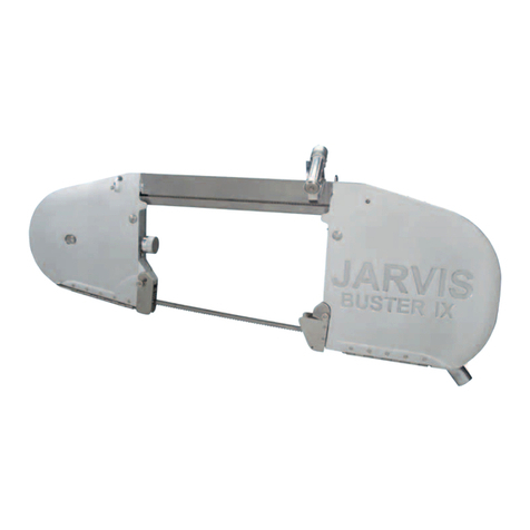
Jarvis Buster IX User manual

Jarvis

Jarvis Buster IX User manual

Jarvis 700--FS User manual

Jarvis

Jarvis 700--FS User manual

Jarvis ERS-1 User manual

Jarvis

Jarvis ERS-1 User manual

Jarvis MCS 300 User manual

Jarvis

Jarvis MCS 300 User manual

Jarvis 1000-FS Troubleshooting guide

Jarvis

Jarvis 1000-FS Troubleshooting guide

Jarvis SEC 180-2 User manual

Jarvis

Jarvis SEC 180-2 User manual

Jarvis NBS-1 Troubleshooting guide

Jarvis

Jarvis NBS-1 Troubleshooting guide

Jarvis SER-03 User manual

Jarvis

Jarvis SER-03 User manual

Popular Saw manuals by other brands

Total TS1141856 manual

Total

Total TS1141856 manual

Metabo KGS 216 M operating instructions

Metabo

Metabo KGS 216 M operating instructions

Milwaukee HEAVY DUTY HD18 CS-0 Original instructions

Milwaukee

Milwaukee HEAVY DUTY HD18 CS-0 Original instructions

Bosch GTS 10 J Professional Original instructions

Bosch

Bosch GTS 10 J Professional Original instructions

Meec tools 012595 operating instructions

Meec tools

Meec tools 012595 operating instructions

Black & Decker CS355 Original instructions

Black & Decker

Black & Decker CS355 Original instructions

Asada 200SP instruction manual

Asada

Asada 200SP instruction manual

Cembre RDS-14P Operation and maintenance manual

Cembre

Cembre RDS-14P Operation and maintenance manual

SAINT-GOBAIN Norton Clipper CST 100 ALU operating instructions

SAINT-GOBAIN

SAINT-GOBAIN Norton Clipper CST 100 ALU operating instructions

Worx BladeRunner X2 WX572 Original instructions

Worx

Worx BladeRunner X2 WX572 Original instructions

Logan Graphic Products F100-2 instruction manual

Logan Graphic Products

Logan Graphic Products F100-2 instruction manual

Holzmann TK 305 user manual

Holzmann

Holzmann TK 305 user manual

Grizzly G0817 owner's manual

Grizzly

Grizzly G0817 owner's manual

Wen 36055 manual

Wen

Wen 36055 manual

PrimAster PMAAS 40 Original instructions

PrimAster

PrimAster PMAAS 40 Original instructions

BorMann Evolution BEV2040 owner's manual

BorMann

BorMann Evolution BEV2040 owner's manual

Bosch PROFESSIONAL GTS 10 operating instructions

Bosch

Bosch PROFESSIONAL GTS 10 operating instructions

RIDGID R4122 Repair sheet

RIDGID

RIDGID R4122 Repair sheet

manuals.online logo
manuals.online logoBrands
  • About & Mission
  • Contact us
  • Privacy Policy
  • Terms and Conditions

Copyright 2025 Manuals.Online. All Rights Reserved.