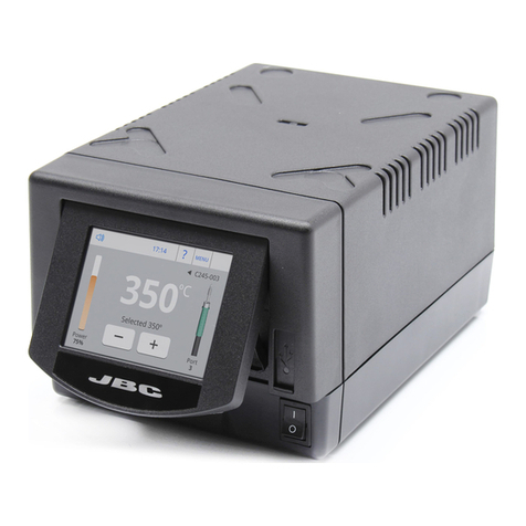
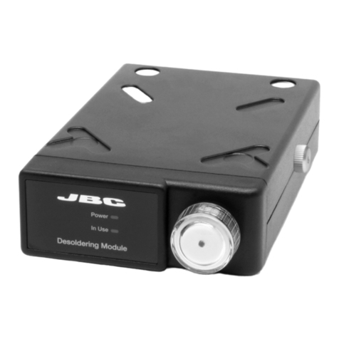
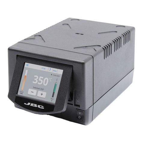
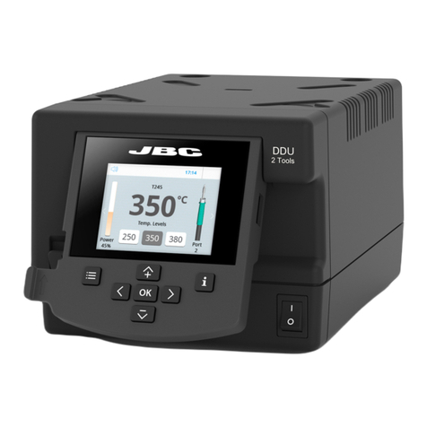
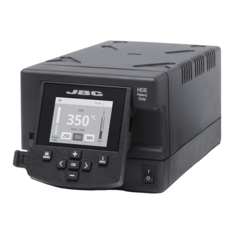
jbc UCR Manual

PROGRAMMERS GUIDE
Communication Protocol for
Automated Processes
Control Units
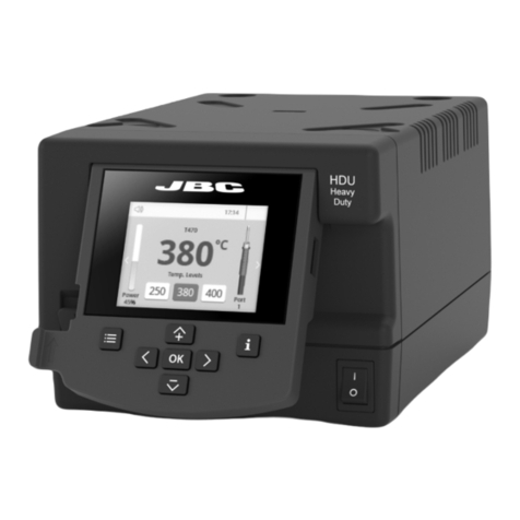
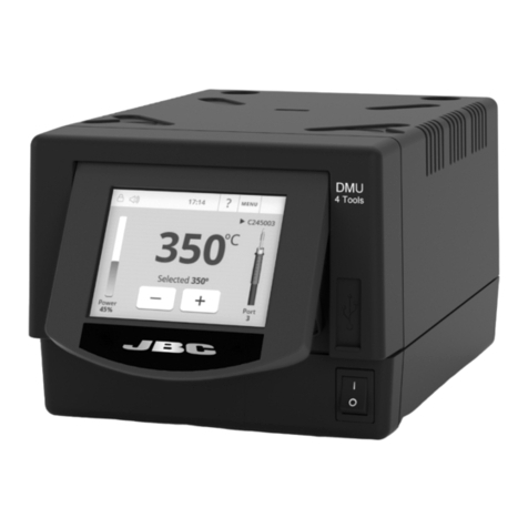
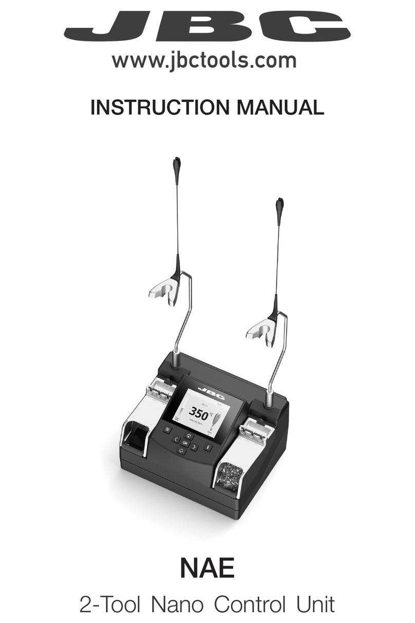
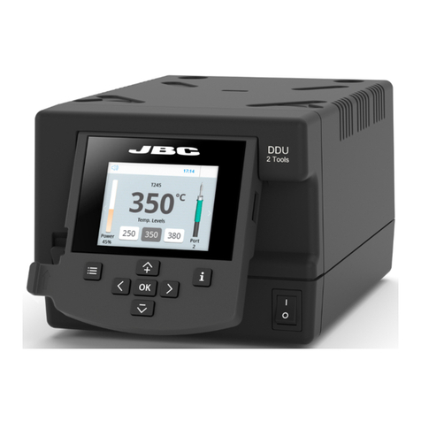
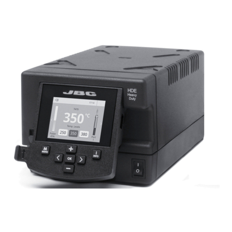
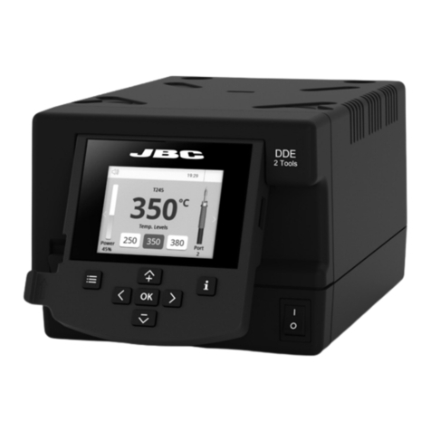
UCR, ALE, NAE, DDE, DME and HDE

This manual corresponds to the following references:
- UCR-A
- ALE-UA/UVA
- NAE-C (and previous versions)
- DDE-C (and previous versions)
- DME-A
- HDE-UD (and previous versions)
2

Physical Layer (PHL) for UCR
Communications Connector
- UCR Control Unit for Robot can be
connected to a PLC using a five-pin
Communications Cable (Ref. 0020261).
- Serial communication type is RS-232,
configured as 19200 bps, eight (8) data
bits, no (N) parity bit and one (1) stop bit
(19200-8N1).
- The communication connector provides
“switch” input.
- For a proper connection, it is necessary to
connect only 3 cables to the corresponding
3 pins at a typical DB9 male connector (PLC
or computer).
Communication Protocol
Communication protocol was developed to help you set up the communication between soldering
stations and a robot (PC or PLC).
It can be applied to the following JBC’s control units:
- UCR Control Unit for Robot
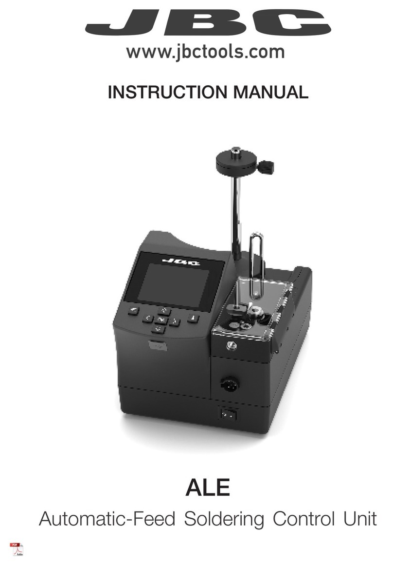
- ALE Automatic-Feed Soldering Control Unit
- NAE 2-Tool Control Unit
- DDE 2-Tool Control Unit
- DME 4-Tool Control Unit
- HDE Heavy Duty Control Unit
The protocol is divided into three layers:
- PHL: Physical layer
- DLL: Data link layer
- APL: Application layer (depends on station model)
3
40 mm
50 mm
60 mm
80 mm
100 mm
130 mm 130 mm
para manuales - color gris
200 mm
300 mm

1 3
5
2 4
Physical Layer (PHL) for ALE, NAE, DDE, DME and HDE Control
Units
- JBC control units can be connected to a PLC by a RJ12 direct cable (ref. 0019751) and DB9-
RJ12 Adapter (ref. 0015383).
- Serial communication type is RS-232, configured as 19200 bps, eight (8) data bits, no (N) parity
bit and one (1) stop bit (19200-8N1).
Front view
Control Box connector
Pin distribution
Pin Color Description
1 Brown Not used
2 White Serial input: RS232 RX
3 Blue Common reference:
GND for RS232 and pedal
4 Black Switch input: 0V or 24V to start feeding.
Leave it open to stop.
5 Grey Serial output: RS232 TX
Communications Connector
Switch input activates the Control Box, using a relay or transistor digital output. Digital output from
the PLC to the switch input can be PNP or NPN style, as well as a relay contact.
Transmitted data output - Grey cable
Pedal activation by
relay or digital output
Ground - Blue cable
Brown cable
Black cable
Received data input - White cable
DB9
Connector
5
4
9
8
7
6
3
2
1
Communications Cable
Ref. 0020261
Optional:
4

5 46 3 2 1
Data Link Layer (DLL) Applies to all
With no address
With address (factory default)
Start Control Header* Control Command Data* Stop Check
1 byte 1 byte 3 bytes 0 or 5 bytes 1 byte 1 byte
STX `R´, `W¨, À´, `N´ “code” “-9999” to “99999” ETX BCC
Start Source
Address
Target
Address
Control
Header*
Control
Command Data* Stop Check
1 byte 2 bytes 2 bytes 1 byte 3 bytes 0 or 5 bytes 1 byte 1 byte
STX “00” to “99” “00” to “99” `R´, `W¨, À´, `N´ “code” “-9999” to “99999” ETX BCC
The frame format is shown in the tables below. By factory settings, communications are made with
addresses. They can be disabled using W-SAD command. Depending on the command used, the
Data field* is not necessary.
*Info
Control Header Field* Data Field
R (Read) Is not used
W (Write) Used
A(Acknowlegement) Response to Reading Comands Used
Response to Writing Comands Is not used
N (Negative Acknowlegement) Used
Robot Station Connector
Pin distribution
Pin Description
1 Not used
2 Common reference: RS232 GND
3 Serial input: RS232 RX
4 Serial output: RS232 TX
5 Common reference: RS232 GND
6 Not used
Female RJ12
Connector
5
40 mm
50 mm
60 mm
80 mm
100 mm
130 mm 130 mm
para manuales - color gris
200 mm
300 mm

Frame Fields
Start
Source Address
Target Address
Control Header
Control Command
Data
Stop
Check
Start of transmission.
Corresponds to the character STX of ASCII code (0x02).
The Source Address range is from “00” to “99”.
The factory setting for Robot Address is “00”.
The Target Address range is from “00” to “99”.
Factory settings for JBC devices are as follows:
· Soldering Stations Address is “01”
· Solder Feeder Address is “10”
· Fume Extractor Address is “20”
Four Codes are used (see table from page 5).
Select the command to be used (see pages 11-29).
Composed of five digits. First tens of thousand is sent and thereafter
successively until the last unit.
Example: in order to send “12345” it is first sent “1”, and finally “5”.
If it is a negative number, the minus sign is at the tens of thousands
digit, shown as an ASCII character “-”.
Example: In order to send “-50”, the data will be sent is “-0050”.
If the number has less than five digits, then zeros will be placed before.
Example: in order to send “375” the data will be sent is “00375”.
End of transmission.
Corresponds to the ASCII code character ETX (0x03).
This is an error Check Field. The value is obtained by calculating the
logic function XOR for the whole frame, excluding the BCC.
6

Command
Frame A
Frame Reception
The Robot sends a Command Frame to the JBC device. This information is send to the Application
Layer (APL). The Command Frame obtained from the robot is correct if it has the correct length and
“starts with STX + finishes with ETX + correct BCC”.
The JBC device will send a Response Frame. In the case of a Response Frame with errors, the Robot
determines the number of consecutive Command Frames that will send to the JBC device. If the
Robot receives a Response Frame with errors, it cannot be resent by the JBC device.
The JBC device does not expect ACK/NAK from the Robot.
Robot
Command
Frame A
Response
Frame A
Robot
JBC Device JBC Device
Command
Frame A
Response
Frame A
Response
Frame A
NAK
7
40 mm
50 mm
60 mm
80 mm
100 mm
130 mm 130 mm
para manuales - color gris
200 mm
300 mm

Application Layer (APL)
Tools:
Ports:
Number Description
0Without tool
1T210
2T245/ T470
2TR245/TR470
3PA120/AM120
4HT420/AT420
5DS360
6DR560
7NT115
8NP115/A N115
9TRA245/TRA470
Number Description
1Port 1
2Port 2
3Port 3
4Port 4
The robot starts the communication with a Command Frame and the JBC device sends a Response
Frame. For a detailed functional description, see the tables with the command overview starting on
pag e 11.
- Temperature is always shown in ºC.
- The power is given in thousands of the theorical maximum JBC Device power [%] without decimals.
Station Errors:
Number Description
00000 OK
00001 Stop due by overload (TRAFO)
00002 Temperature sensor error
00003 Memory
00004 Mains frequency
00005 JBC device model
00006 Not connected MCU tools
00007 Warning overload (TRAFO)
8

Port Errors:
Number Description
00000 OK
00001 Short-circuit
00002 Short-circuit non-recoverable, JBC Device should be restarted
00003 Open circuit
00004 No tool
00005 No tool accepted
00006 Tool detection
00007 Stop due by maximum powers (not implemented)
00008 Stop due by overload (MOS)
00009 Warning overload (MOS)
Communication Errors:
Number Description
00001 BCC error (frame error when doing the sum check)
00002 Format error (format is not correct, i.e. incorrect size)
00003 Out of range (modified value out of limit)
00004 Control error (control code not accepted)
00005 Robot Control Mode Error
(in JBC Device Menu is “off” for “Robot Mode” selected)
00006 Station model error (station unknown)
99999 Undefined (error not defined)
Tool Operating Status:
(Standard Processes)
Number Description
00000 Working
00001 Stand, it still has not gone into sleep mode (delay)
00002 Sleep*
00003 Hibernation*
*Not selectable with W-PSx commands.
9
40 mm
50 mm
60 mm
80 mm
100 mm
130 mm 130 mm
para manuales - color gris
200 mm
300 mm

The following diagram shows the soldering stations work flow:
Tool Operating Status:
(Automated Processes)
Suction Status:
Number Description
00000 Working
00010 Cooling
Number Description
00000 Desoldering OFF
00100 Desoldering ON
Work Stand
WPS100001 time delay time delay
Sleep Hibernation
Extractor
WPS100000
WPS100000
WPS100000
WPS100010
Motor Status:
Number Description
00000 Motor OFF
01000 Motor ON and forward motion (dispensing)
02000 Motor ON and backward motion
10

Commands
W-PSx
R-PSx
W-STx
Code Description Details
Write - Port
Status + port
Read - Port
Status + port
Write - Select
Temp. + port
Sets the Tool Operating Status.
Replace the ‘x’ with the number of the destination port
in ASCII, for example “WPS1”.
The Data Field contains the selected Operating Status
for the tool.
Send “00000” for Working, “00010” for Extractor (stand
by) or “00001” for Stand.
The Tool Operating Status is managed by the robot.
Except sleep and hipermantion mode, whose status
are reached after time delay. See page 10 for more
information.
The JBC device answers with an “A-PSx” (example
“APS1”).
To get the Tool Operating Status.
See page 10 for identifier information.
The ‘x’ must be replaced with the number of the
destination port in ACCII, for example “RPS1”.
The Data Field contains the tool operating status.
The JBC device respons with an “A-PSx”.
Sets the Tip Working Temperature.
Replace the ‘x’ with the number of the destination port
in ASCII, for example “WST1”.
The Data Field contains the selected temperature,
expressed in °C. The temperature modification must be
done in steps of 5 degrees.
The JBC device responds with an “A-STx”, for expamle
“AST1”.
Warning: selected temperature is a volatile setting,
therefore use the W-NVS frame in order to save it into
the station memory.
11
40 mm
50 mm
60 mm
80 mm
100 mm
130 mm 130 mm
para manuales - color gris
200 mm
300 mm

R-STx
R-TTx
R-PPx
Code Description Details
Read - Select
Temp. + port
Read - Tip
Temp. + port
Read - Port Power +
port
To get the set Working Temperature.
Replace the ‘x’ with the number of the destination port
in ASCII, for example “RST1”.
The JBC device responds with an “A-STx”.
The Data Field contains the current Working
Temperature, expressed in °C , for expamle
“AST100350”.
To get the current Tip Temperuature.
The ‘x’ must be replaced with the number of the
destination port in ACCII (example “RTT1”).
The JBC device respons with an “A-TTx” and the Data
Field contains the current tip temperature expressed in
°C, expamle “ATT100183”.
To get the current power delivered to the tip.
The ‘x’ must be replaced with the number of the
destination port in ACCII (example “RPP1”).
The Data Field contains the delivered power expressed
in ‰, for example “APP100840” for 84%.
The JBC device response with A-PPx.
12

R-Axy
W-Axy
W-MAT
Code Description Details
Read - Adjust
Temperature
+ port + tool
Write - Adjust
Temperature
+ port + tool
Write -
Maximum
Temperature
To get the Tool Adjustment Temperature.
The ‘x’ must be replaced with the number of the
destination port and the “y” with the tool number in
ACCII, for example “RA12” for port 1 and tool TR245.
See page 8 for identifier information.
The JBC device answers with an “A-Axy”.
The Data Field contains the Tool Ajustment
Temperature, expressed in °C.
Sets a temperature offset.
Used when a tool temperature fine-adjustment is
needed.
The ‘x’ must be replaced with the number of the
destination port and the “y” with the tool number in
ACCII, for example “WA12”, for port 1 and tool TR245.
See page 8 for identifier information.
The Data field contains the Adjustment Temperature
for the tool, expresed in °C. The maximum adjustment
temp is +/- 50°C, for example “WA1200012”. The
temperature offset must be done in steps of 1 degree.
Note: In order to send -50 °C, the data will be sent is
“-0050”.
The JBC device answers with an “A-Axy”.
Set the Maximum Temperature selectable with W-STx.
The Data Field contains the Maximum Work
Temperature, expressed in °C
The JBC device responds with an “A-MAT”.
13
40 mm
50 mm
60 mm
80 mm
100 mm
130 mm 130 mm
para manuales - color gris
200 mm
300 mm

R-MAT
R-MIT
W-MIT
W-Sxy
Read -
Maximum
Temperature
Read - Minimum
temperature
Write - Minimum
temperature
Write - Sleep
Temperature
+ port + tool
To get the Maximum Temperature selectable With
W-STx.
The JBC device responds with an “A-MAT”.
The Data Field contains the Maximum Working
Temperature, expressed in °C.
To get the Minimum Temperature selectable with
W-STx.
The JBC device responds with an “A-MIT”.
The Data Field contains the Minimum Work
Temperature, expressed in °C.
Set the Minimum Temperature selectble with W-STx.
The Data Field contains the Minimum Work
Temperature, expressed in °C.
The JBC device responds with an “A-MIT”
Sets the Sleep Temperature.
The ‘x’ must be replaced with the number of the
destination port and the “y” with the tool number* in
ACCII, for example “WS12”, for port 1 and tool TR245.
See page 8 for identifier information.
The Sleep Temperature must be done in steps of 5
degrees.
The data Field contains the Sleep Temperature for the
tool, expressed in °C.
The JBC device answers with an “A-Sxy”.
Code Description Details
14

R-Sxy Read - Sleep
Temperature
+ port + tool
To get the Sleep Temperature.
The ‘x’ must be replaced with the number of the
destination port and the “y” with the tool number in
ACCII, for example “RS12”, for port 1 and tool TR245.
See page 8 for identifier information.
The JBC device answers with an “A-Sxy”.
The Data Field contains the Sleep Temperature,
expressed in °C.
Code Description Details
W-Dxy
R-Dxy
Write - Sleep
Delay
+ port + tool
Read - Sleep
delay
+ port + tool
Sets the Sleep Delay Time.
The ‘x’ must be replaced with the number of the
destination port and the “y” with the tool number* in
ACCII, for example “WD12”, for port 1 and tool TR245.
See page 8 for identifier information.
The data Field contains the delay time, to enter into
sleep since the command W-PSx-00001 is received.
The Sleep Delay must be set in steps of 1 minute with
a range from 0 to 9.
To disable the sleep mode, send “99999”.
The JBC device answers with an “A-Dxy”.
To get the Sleep Delay Time.
The ‘x’ must be replaced with the number of the
destination port and the “y” with the tool number* in
ACCII, for example “RD12”, for port 1 and tool TR245.
See page 8 for identifier information.
The JBC device answers with an “A-Dxy”.
The Data Field contains the current Sleep Delay Time,
expressed in minutes.
If get answered “99999”, the sleep mode is disabled.
15
40 mm
50 mm
60 mm
80 mm
100 mm
130 mm 130 mm
para manuales - color gris
200 mm
300 mm

W-Hxy
R-Hxy
Write -
Hibernation
Delay + port +
tool
Read -
Hibernation
Delay + port +
tool
Sets the Hibernation Delay Time.
The ‘x’ must be replaced with the number of the
destination port and the “y” with the tool number* in
ACCII, for example “WH12”, for port 1 and tool TR245.
See page 8 for identifier information.
The Data Field contains the delay time to enter into
Hibernation since the Sleep Tool Operating Status is
reached. The Hibernation Delay must be set in steps
of 5 minutes with a range from 0 to 60 minutes.
The Data Field contains the current Hibernation Delay
Time, expressed in minutes.
To disable the Hibernation mode, send “99999”.
The JBC device answers with an “A-Hxy”.
To get the Hibernation Delay Time.
The ‘x’ must be replaced with the number of the
destination port and the “y” with the tool number* in
ACCII, for example “RH12”, for port 1 and tool TR245.
See page 8 for identifier information.
The JBC device answers with an “A-Hxy”.
The Data Field contains the Hibernation Delay Time,
expressed in minutes.
If get answered “99999”, the Hibernation Mode is
disabled.
Code Description Details
16

R-TT
R-QTx
W-HAx
R-EDx
Read -
Transformer
Temperature
Read - Transistor
Temp. + port
Write - Higher
Temp
Alarm + port
Read - enter
delay time
(sleep/
hibernation)
+ port
To get the Power Supply Temperature.
The JBC device responds with an “A-TT”.
The Data Field contains the Transformer Temperature,
expressed in °C.
To get the current Transitor Temperature.
The ‘x’ must be replaced with the number of the
destination port in ACCII, for example “RQT1”.
The JBC device answers with an “A-QTx”.
The Data Field contains the current Transitor
Temperature, expressed in °C.
Sets the upper Temperature Alarm limit.
The ‘x’ must be replaced with the number of the
destination port in ASCII, for example, “WHA1”.
The data Field contains the upper Temperature Alarm
limit, epressed in °C. The temperature modification
must be done in steps of 5 degrees.
The JBC device responds with an “A-HAx”.
To get the remaining delay time before enter into sleep
or hibernation mode.
The ‘x’ must be replaced with the number of the
destination port in ACCII, for example “RED1”.
The JBC device answers with an “A-EDx”.
The Data Field contains the remaing time, expressed
in seconds.
Code Description Details
17
40 mm
50 mm
60 mm
80 mm
100 mm
130 mm 130 mm
para manuales - color gris
200 mm
300 mm

R-HAx
W-LAx
R-LAx
Read - Higher
Temp.
Alarm + port
Write - Lower
Temp
Alarm + port
Read - Lower
Temp
Alarm + port
To get the Upper Temperature Alarm limit.
The ‘x’ must be replaced with the number of the
destination port in ACCII, for example “RHA1”.
The JBC device answers with an “A-HAx”.
The Data Field contains the upper Temperature Alarm
limit, expressed in °C.
Sets the lower Temperature Alarm limit.
The ‘x’ must be replaced with the number of the
destination port in ASCII, for example, “WLA1”.
The Data Field contains the Lower Temperature Alarm
limit, expressed in °C. The temperature modification
must be done in steps of 5 degrees.
The JBC device responds with an “A-LAx”.
To get the Lower Temperature Alarm limit.
Replace the ‘x’ with the number of the destination
port in ASCII, for example, “RLA1”.
The JBC device responds with an “A-LAx”.
The Data Field contains the lower Temperature Alarm
limit, expressed in °C.
Code Description Details
18

R-HDx Read - Higher
Delay
Alarm + port
To get the delay time to activate the Upper
Temperature Alarm.
Replace the ‘x’ with the number of the destination
port in ASCII, for example “RHD1”.
The Data Field contains the delay time to activate the
Upper Temperature Alarm, expressed in seconds and
hundreds of seconds, according to:
“Format “ss.cc” in ASCII. “ss” corresponds to the
time in seconds, and “cc” corresponds to the time
in hundredths of a second. Example: “01.60” means
1,6s; “00.10” means 0,1s.
When the tip temperature is above the Upper
Temperature Alarm for a longer time than the delay set
in the HDx, the Alarm will be set to 1.”
The Data Field contains the Higher Delay Alarm.
“99999” means that the alarm is disabled.
Code Description Details
W-HDx Write - Higher
Delay
Alarm + port
Sets the delay time to activate the Upper Temperature
Alarm. The delay time starts when the tip temperature
is above the value in HAx.
Replace the ‘x’ with the number of the destination
port in ASCII, for example “WHD1”.
The Data Field contains the delay time to activate the
Upper Temperature Alarm, expressed in seconds and
hundrets of seconds, according to:
Format “ss.cc” in ASCII. “ss” corresponds to the
time in seconds, and “cc” corresponds to the time in
hundreds of a second. Example: “01.60” means 1,6s;
“00.10” means 0.1s.
The JBC device responds with an “A-HDx”.
To disable the Hibernation mode, send “99999”.
19
40 mm
50 mm
60 mm
80 mm
100 mm
130 mm 130 mm
para manuales - color gris
200 mm
300 mm

W-LDx
R-LDx
Write - Lower
Delay
Alarm + port
Read - Lower
Delay
Alarm + port
Sets the delay time to activate the Lower Temperature
Alarm.
The delay time is counted, when the temperature falls
below the “Lower Temperature Alarm” limit; previously
defined with LAx.
Replace the ‘x’ with the number of the destination
port in ASCII, for example “WLD1”.
The Data Field contains the delay time to activate the
“Lower Temperature Alarm”, expressed in seconds
and hundrets of seconds, according to:
Format “ss.cc” in ASCII. “ss” corresponds to the
time in seconds, and “cc” corresponds to the time
in hundredths of a second. Example: “01.60” means
1,6s; “00.10” means 0,1s.
The JBC device responds with an “A-LDx”.
To disable the Hibernation mode, send “99999”.
To get the delay time to activate the Lower
Temperature Alarm.
When the tip temperature falls down the Lower
Temperature Alarm for a longer time than the delay set
in the W-Lax, the Alarm will be set to 10.
Replace the ‘x’ with the number of the destination
port in ASCII, for example “RLD1”.
The Data Field contains the delay time to activate the
“Lower Temperature Alarm”, expressed in seconds
and hundrets of seconds, according to:
Format “ss.cc” in ASCII. “ss” corresponds to the
time in seconds, and “cc” corresponds to the time
in hundredths of a second. Example: “01.60” means
1,6s; “00.10” means 0,1s.
The JBC device responds with an “A-LDx”
“99999” means that the alarm is disabled.
Code Description Details
20
Other manuals for UCR
1
This manual suits for next models
5
Table of contents
Other jbc Control Unit manuals
Popular Control Unit manuals by other brands

Siemens
Siemens SINAMICS G120 manual

Linear Technology
Linear Technology DC1589A Quick start guides

Ke Kelit
Ke Kelit Flamco FlexBalance EcoPlus C 1 manual

DEMA
DEMA 481-2 installation instructions

Rockwell Automation
Rockwell Automation Micro800 Series Wiring diagrams

AMR
AMR LS-3000-220 Installation and setup instructions