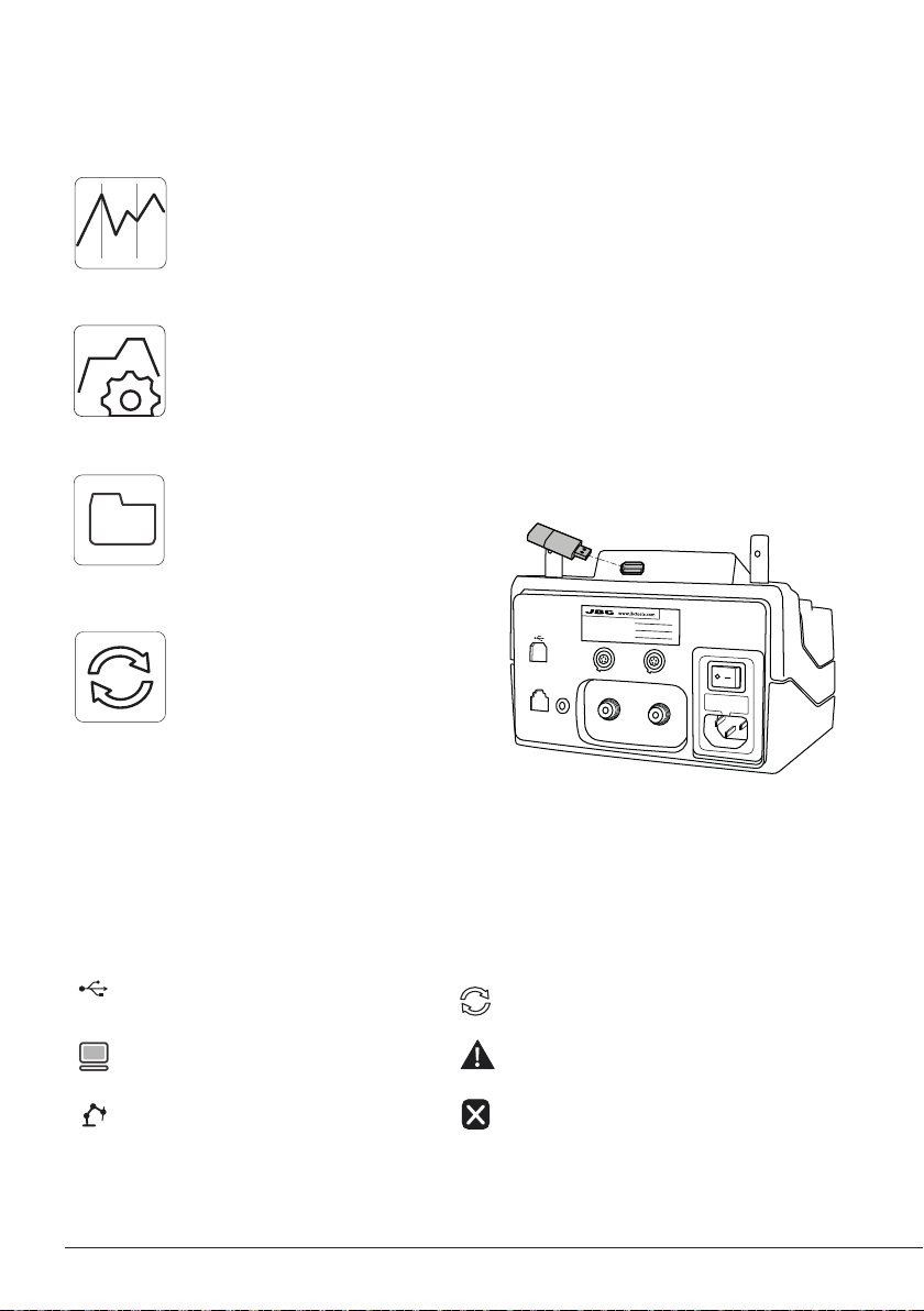
Export graphics
Insert a USB flash drive into the USB-A
connector to save your soldering
process in csv format.
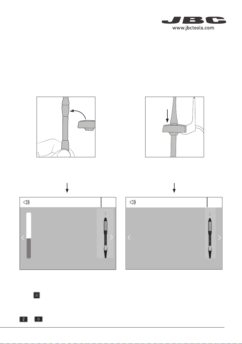
Profiles
Advanced Functionalities
It provides detailed graphics of tip temperature and power delivery in real time during
solder joint formation for analysis purposes. This helps you decide how to adjust your
process or which tip to use to obtain the best quality soldering.
Graphics
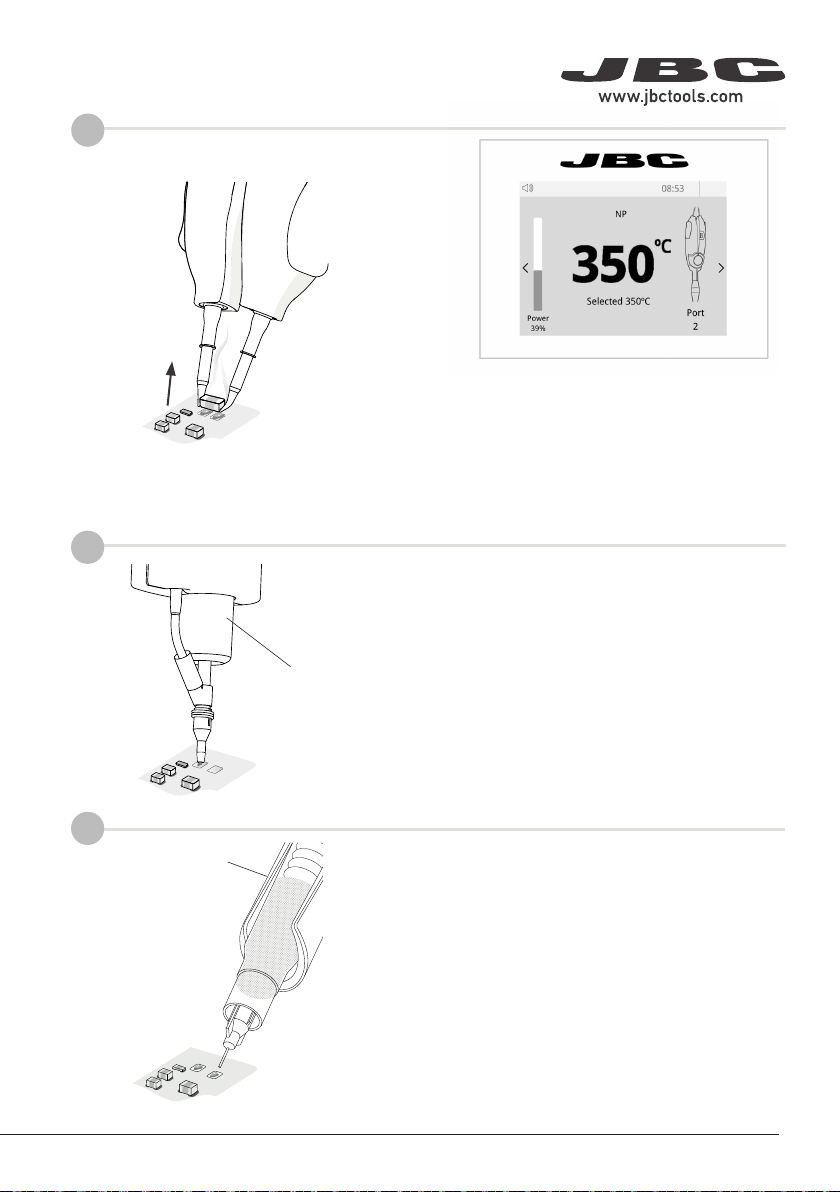
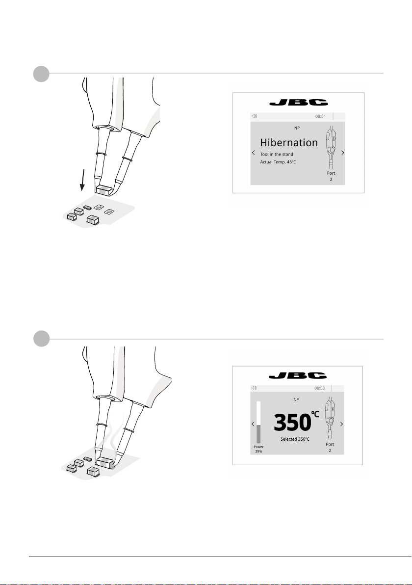
Designed to avoid thermal shock when soldering Ceramic Chip components like MLCC,
this new and unique feature allows controlling the heating rate to gradually increase the
temperature of the component through all the phases of the soldering process. Up to 25
fully configurable soldering profiles can be stored.
System Notifications
The following icons will be displayed on the screen’s status bar.
Station update
Download the JBC Update File from
www.jbctools.com/software.html
Insert the USB flash drive with the file
downloaded to the station.
Files
Update
USB flash drive is connected.
Station is controlled by a PC.
Station is controlled by a robot down-
loaded to the station.
Station software update. Press INFO to start
the process.
Warning. Press INFO for failure description.
Error. Press INFO for failure description,
the type of error and how to proceed.
NAE
Control Unit
PORT
2
ROBOT
PEDAL
2
NAE
Control Unit
PORT
2
ROBOT
PEDAL
2
C115
C11
C105 /
C105 / C115
19:29
19:29
Port
2
Actual Temp. 25ºC
NT105
ºC
Power
45%
Selected 350ºC
350
Port
2
NT105
Hibernation
19:29
Port
2
Actual Temp. 25ºC
AN115
Hibernation
19:29
ºC
Power
45%
Selected 350ºC
350
Port
2
AN115
No Yes
NAE
Control Unit
PORT
2
ROBOT
PEDAL
2
PORT
1
PEDAL
2
666