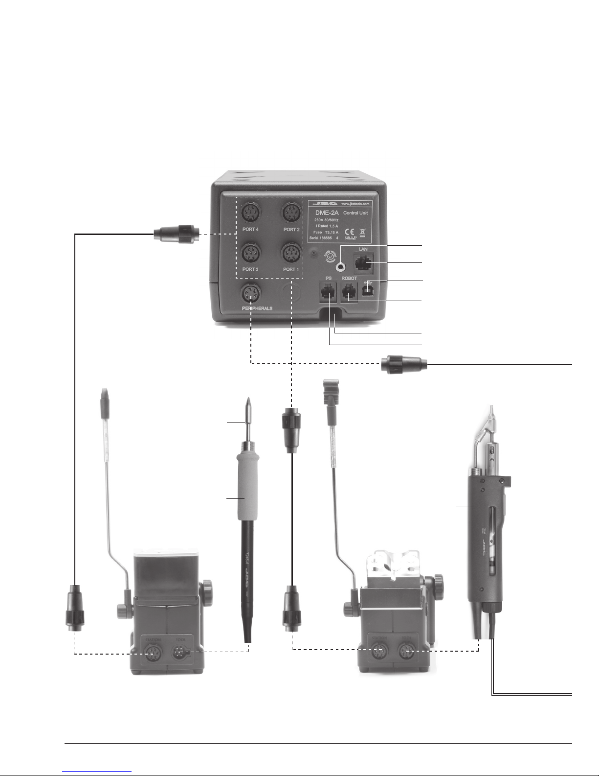
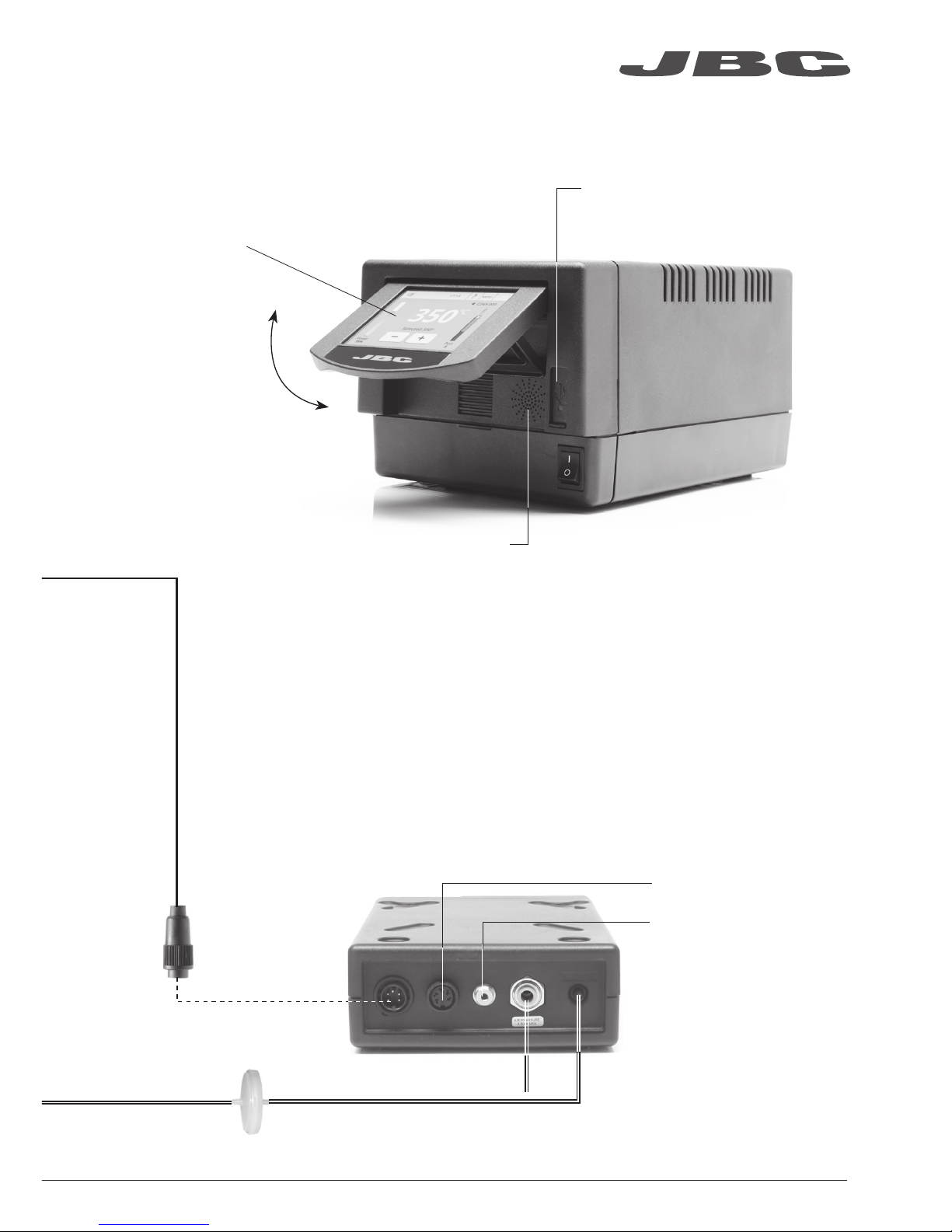
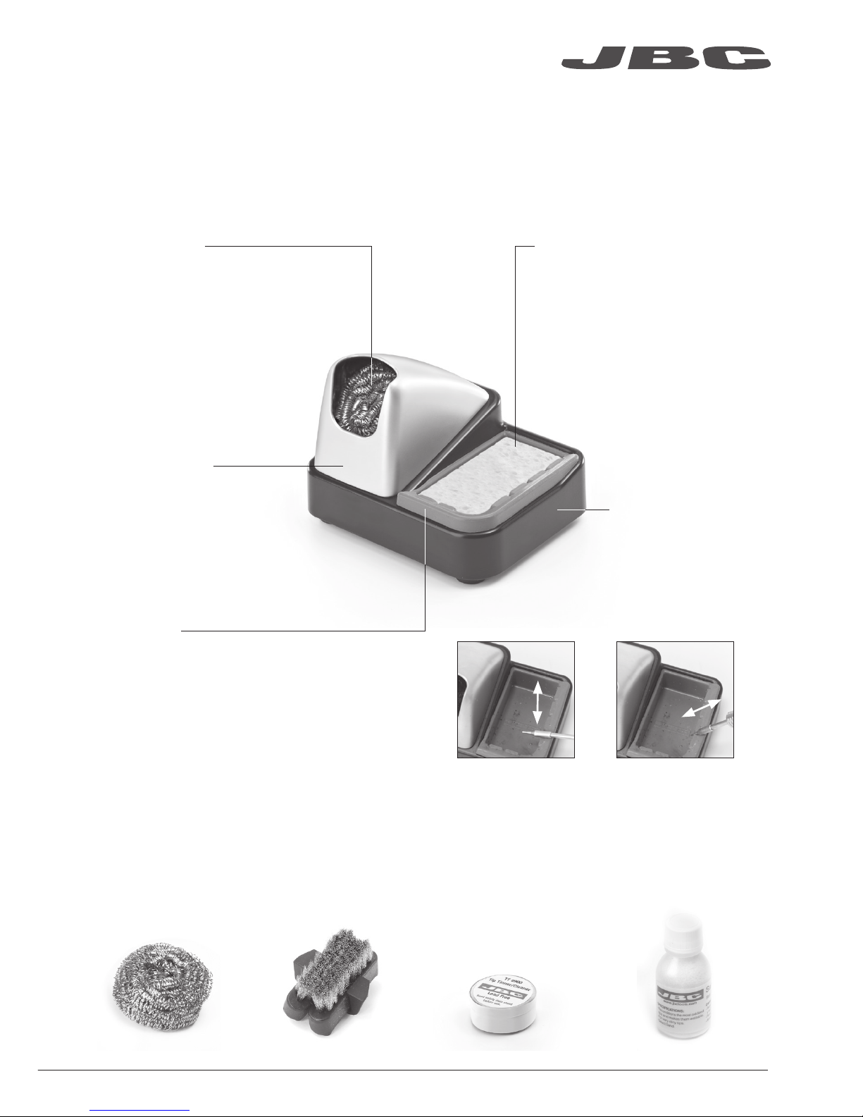
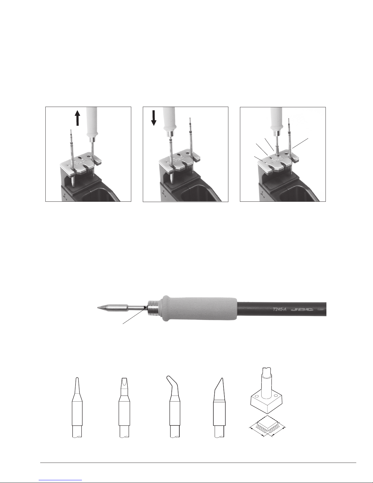
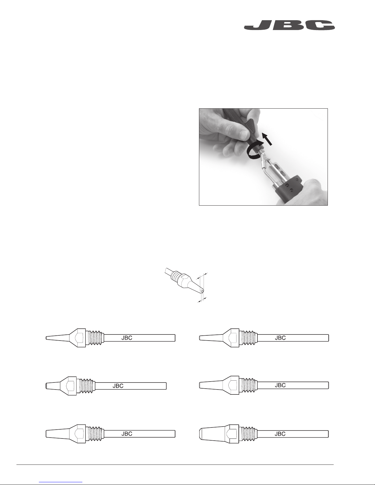
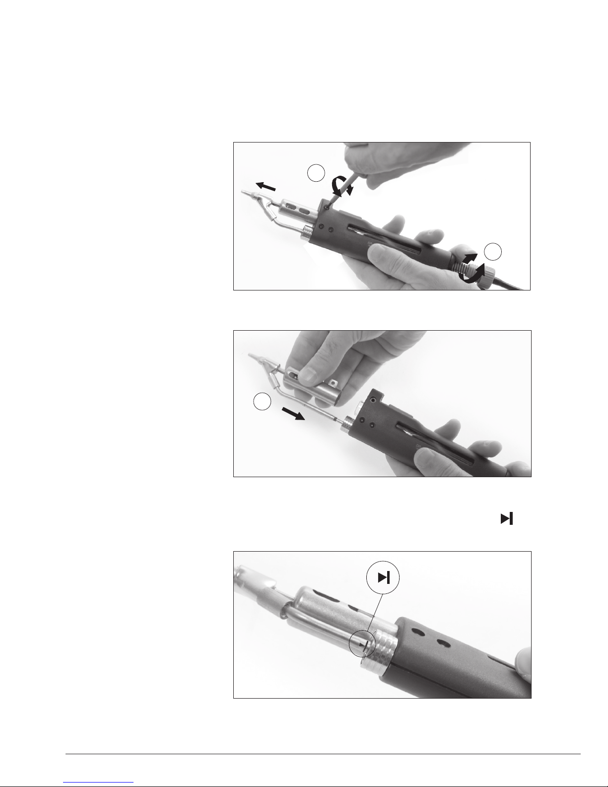
jbc DMVE-1A User manual

Premium
4 Tools Rework station
with Pneumatic Pump
Ref. DMVE-A
www.jbctools.com

Packing List
The following items should be included:
Stand Cable ................ 2 units
Ref. 0011283
Stand ................ 1 unit
Ref. AD-SD
Sponge ............................. 1 unit
Ref. S0354
Metal Brush .................... 1 unit
Ref. CL6217
Pneumatic Desoldering
Module .............................. 1 unit
Ref. MVE-A
Tip Cleaner.........1 unit
Ref. CL9885
Module Cable ............... 1 unit
Ref. 0014874
DME Control Unit ................. 1 unit
Ref. DME-1A (120V)
DME-2A (230V)
DME-9A (100V)
Union Flanges ................. 1 unit
Ref. 0011356
Desoldering
Iron ..................... 1 unit
Ref. DR560-A
Stand ................. 1 unit
Ref. DR-SD
Power cord .................... 1 unit
Ref. 0010569 (230V)
0013671 (100/120V)
General Purpose
Handle ............... 1 unit
Ref. T245-A
2

Manual ............................. 1 unit
Ref. 0016078
Premium
4 Tools Rework station
with Pneumatic Pump
Ref. DMVE-A
Suction Filter .................1 unit
Ref. 0821830
Cotton Filter ................. 1 unit
Ref. 0781046
It contains 10 filters
DR560 Accessories
Ref. 0010211
Internal gasket ................ 2 u.
Ref. 0812360
Tip cleaning set .......................................... 1 unit
Ref. 0965970
Filter Box .................... 1 unit
Ref. 0780840
It contains 10 filters
Spanner ....................... 1 unit
Ref. 0780550
Tin deposit .................... 1 unit
Ref. 0812620
Long Tip Cleaning set ....................... 1 unit
Ref. 0965760
Metal tin diposit ....... 1 unit
Ref. 0812630
Tips ............................. 3 units
Ref. C560005
Ref. C560013
Ref. C560004
Cleaning stick ................1 unit
Ref. 0786640
Cartridges ..................... 2 units
Ref. C245903 (x1)
C245906 (x1)
Filter Box .........................1 unit
Ref. 0005966
It contains
50 filters Venturi Filter ...................1 unit
Ref. 0008446
www.jbctools.com
3
www.j bct ool s.c om

Features
Work simultaneously with up to 2 tools and join each station port with 1 module + 1 pedal (Peripherals).
Stand
Ref. AD-SD
General
Purpose
Handle
Ref. T245-A
Desoldering Iron
Ref. DR560-A
Cartridge
Ref. C245903
Ref. C245906
Tip
Ref. C560004
Ref. C560005
Ref. C560013
Stand
Ref. DR-SD
Stand Cable
Ref. 0011283
RJ12 connector for Robot
USB-B connector
Equipotential connection
Power Socket
RJ12 connector for PSE
RJ45 connector for LAN
4

Pneumatic Desoldering Module
Ref. MVE-A
To another peripheral
To Pedal
Ref. P-005
USB-A connector
3.5” Color TFT
Touch screen
Tilt the display for
easy reading
Suction Filter
Ref. 0821830
Module Cable
Ref. 0014874
Speaker
Air pressure
(4-6 bar)
www.jbctools.com
5

Stand
Ref. AD-SD
Quick tip changer
Permits switching
cartridges without
interrupting
your work.
Adjustable
tool holder
Suits your
work
position.
Adjustable
cable
collector
Adjustable Stands
Stand
Ref. DR-SD
Quick tip changer
Holding tip system
for easy change.
Cable collector
Keeps working area free of cable.
6

Improve thermal transfer by cleaning the tip after each solder joint.
Tip Cleaner
Optional
Brass wool
Ref. CL6210
Inox wool
Ref. CL6205
Brushes
Ref. CL6220
Tip-tinner
Ref. TT-A
Sand
Ref. CL6211
Splashguard
Non-slip base
Sponge
Ref. S0354
Wiper
Ref. CL0236
Very effective cleaning
method. It leaves a small layer
of solder on the tip to prevent
oxidation between cleaning
and rewetting.
It prevents splashing of
solder particles when
using the brass wool. Heavy weighted non-
slip base for simple-
handed cleaning.
The least harmful cleaning
method. Keep the sponge damp
with distilled water when working
to avoid tip wear.
A temperature resistant receptacle lets
the operator remove excess solder by
gentle tapping or wiping. It can be easily
removed for cleaning.
Tapping: Wiping:
Tap gently to remove
excess solder.
Use the slots to
remove remaining
particles.
www.jbctools.com
7

ø 1
ø 1,5
ø 3,5
A
AB
T245 Changing Cartridges
1. Removing 2. Inserting 3. Fixing
Place the handle in the
extractor and pull to
remove the cartridge.
Place the handle on top of
the new cartridge and press
down slightly.
Use the holes for fixing the
cartridge* as follows:
A. For straight C210.
B. For curved C210.
C. For curved C245.
D. For straight C245.
*Important
It is essential to insert the cartridges as far as the mark for a proper connection.
B
C
A
D
Compatible cartridges
The T245 handle works with C245 cartridges. Find the model that best suits your soldering needs
in www.jbctools.com
Round Chisel Round bent Bevel Special models
Save time and change cartridges safely without switching the station off.
8
Mark

A ø
Bø
DR560 Changing Tips
This operation should be done while the tip is hot, not below 250°C, so that any tin left inside is in
molten state.
250ºC minimum
C560-001 C560-002
C560-003
C560-004 C560-009
C560-014
C560-001 ØA=1,4 ØB=0,6 Ømax. pin=0,4 C560-002 ØA=1,8 ØB=0,8 Ømax. pin=0,6
C560-003 ØA=2,7 ØB=1 Ømax. pin=0,8
C560-004 ØA=3,2 ØB=1,3 Ømax. pin=1,1 C560-009 ØA=5 ØB=1,3 Ømax. pin=1,1
C560-014 ØA=2,5 ØB=0,8 Ømax. pin=0,6
1. Removing
Unscrew the tip using the spanner
supplied.
2. Inserting
Fit the new tip and tighten with the
spanner to make sure it is air tight.
Compatible Tips
The DR560 works with C560 tips. Find the model that best suits your soldering needs in www.jbctools.com
Here are some C560 tips in real size (mm):
www.jbctools.com
9

DR560 Changing the Heating Element
1. Loosening
The deposit lid needs to be
loosened.
2. Removing
Loosen the screw as shown
and remove the
Heating Element.
3. Placing
Place the new Heating
Element and follow the steps
conversely.
2
1
3
To perform this operation, turn off the station or disconnect the tool.
Important
For a proper connection it is essential to insert the cartridge by lining it up to the mark .
10

DR560 Tin Deposit Cleaning
1. Removing the lid
3. Inserting the deposit
Check filter
Lid
Check
internal joint
2. Cleaning
The filter and internal joint must be checked
and replaced if dirty or damaged.
Remove the coil to clean the inside of the
deposit with the stick supplied.
The lid must be removed with the DR560 in
vertical position.
The deposit must be inserted with coil filter in
place, positioned between the 2 lines marked
on the tin deposit.
Then the whole unit must be closed by
screwing the lid. Marks
www.jbctools.com
11

Desoldering process
Use a tip with a larger diameter than the pad to achieve maximum aspiration and thermal efficiency.
Place the tip with the
component terminal in the
hole.
After pressing the desoldering key there is a slight delay until the self-contained vacuum pump
stops. This makes sure that the vacuum circuit is completely empty. If any solder remains are left
on a terminal after desoldering it, resolder it with fresh solder and repeat the desoldering operation.
When the solder liquefies,
gently rotate the tip so that
the component terminal can
be lifted off.
Press the vacuum pump
button long enough to remove
the solder.
3. Aspirating1. Placing 2. Rotating
The intake tube should be periodically cleaned by the largest rod.
DR560 Tip Care
Important
DO NOT press the vacuum pump button while tinning the desoldering tip, as the fumes given
off by the flux would quickly block the ducts and the air filter.
12

Peripherals Port 2-DR
17:14
Pedal None
Module None
Module
MVE_a
None
1. Select the module from the list of
peripheral connections. Remember your first
connection is denoted as “a”, the second
being “b”, etc. (e.g. MVE_a, MVE_b,...)
2. Press Menu or Back to save changes.
Once set up, you can change the module
settings by entering the Peripherals Menu.
MVE Initial Setup
Peripherals
After connecting the pneumatic desoldering module (MVE-A), enter the
Peripherals Menu and select the port which you want to join with the module.
MVE Changing the
pump filters
- Use a damp cloth to keep the casing clean.
- Periodically check all cable and tube
connections.
- Keep filters clean to ensure proper solder
suction and replace them when
necessary.
Spare filters
Ref. 0005966
Cotton filters
Ref. 0781046
Suction filter
Ref. 0821830
O Ring
Ref. 0007717
Filter cover
Ref. 0004710
Escape filter
Ref. 0008446
Removing the
pneumatic tubing
- Push the release ring to remove the
pneumatic tubing.
1
2
Release
ring
Important: Do not use sharp pointed objects to open the suction filter.
www.jbctools.com
13

350ºC
Port
3
Power
45%
Selected 350º
+
C245-003
MENU
17:14 ?
Port
3
3. Hibernation
Operation
The JBC Exclusive Heating System
Our revolutionary technology is able to recover tip temperature extremely quickly. It means the user
can work at a lower temperature and improve the quality of soldering. The tip temperature is further
reduced thanks to the Sleep and Hibernation modes which increase the tip life by 5.
1. Work 2. Sleep
When the tool is lifted from the
stand the tip will heat up to the
selected temperature.
When the tool is in the stand,
the temperature falls to the
preset Sleep temperature.
After longer periods of
inactivity, the power is cut off
and the tool cools down to
room temperature.
Tools Menu:
· Set Sleep temperature
· Set Sleep delay
(from 0 to 9 min or no Sleep)
· Set Hibernation delay
(from 0 to 60 min or no
hibernation)
Tools Menu: Tools Menu:
Long time in
the stand
· Adjust temperature and
cartridge
· Set temperature levels
Sleep
Tool in the stand
Actual Temp. 180ºC
Delay to hibernation: 29:30
Port
Hibernation
Actual Temp. 25ºC
MENU
17:14
?
MENU
17:14 ?
14
Port
33

350ºC
Port
3
Power
45%
Selected 350º
+
C245-003
MENU
17:14 ?
MENU
17:14
?
PORT 1
PORT 2
T210
Cartridge C210-001
350ºC
DR560
Cartridge C560-001
Sleep
Tool in the stand / 180ºC
Work Screen
The DME-A offers an intuitive user interface which provides quick access to the station parameters.
Station Information
Help for each parameter
Power indicator
Shows the %
power delivered
for each port
Tool in use
Press here to
see the Ports
Screen
Cartridge
in use
Introduce the
reference for
more precise
temperatures
readings
Station Lock
PIN required
for unlocking
See the information of all ports in real time when pressing the tool image from the Work screen.
Simultaneous control of ports
Tool port
Press any
port for being
displayed in the
Work Screen
Sliding bar
See up to
4 ports
Defined cartridge
If not displayed,
go to “Cartridge
adjustment” in
Tools menu
Tool Status
Tip temperature,
Sleep or
Hibernation
www.jbctools.com
15

17:14 ?
Station Tools Counters
Peripherals
Utilities Info Language Reset
Registers total
and partial
hours for each
port: work, sleep,
hibernation...
Multi-language
Up to 8 languages to choose from.
Personalize
the station:
Station name, PIN
activation, Screen
settings, Robot
activation, Partial
resets...
Adjust tool settings for each port Join station ports with modules and pedals
Menu Screen
Utilities
Select any option and press the station information button to display each parameter description.
Useful additional applications that complement and support your work.
View your
video* via USB,
or import it from
your PC
Unit Converter
ºC - ºF - K
Monitor and
save your
soldering
process to
optimize
production
Connect a
microscope**
via USB and see
your work on
the screen
* Format file video: AVI and MP4 / Resolution: 320x240 / Aspect ratio: 16:9 / Frame rate: 18 FPS
**Recommended model: Dino-Lite AM2011 and equivalent.
17:14 ?
Microscope
Convert
Video
Files Graphs
Calculator
Catalog
16

USB flash drive is connected to
the USB-A.
Station is controlled by a PC.
Station is controlled by a robot.
The station is being updated by a USB
flash drive.
System notifications
Warning.
Press here for description.
Error.
Press here for failure description,
the type of error and how to proceed.
Indicates there is a peripheral to be
installed.
After
connecting
the tool,
introduce the
last 3 reference
numbers of the
cartridge.
Insert the cartridge model and the station will recognize its characteristics (size and shape) to provide
more accurate temperature readings.
The following icons may be displayed on the status bar on the screen.
Cartridge Adjustment
Tools
?
17:14
T245 - port 3
www.jbctools.com
17
Cartridge Adjust C245-003
Temperature adjust 0ºC
Temp. level set Off
Sleep delay 0 min.

By pressing Graphics in the Utilities MENU, temperature and power figures in real
time are displayed for each port. This helps you decide how to adjust your process
or which tip to use to obtain the best quality soldering.
Process analysis
Export graphics
Insert a USB flash drive into the USB-A
connector to save your soldering process in
csv format.
Graphics
Temperature
Power (%)
Change port
Optimize your production after analysing the information provided by the graphics.
5 sec/divp1 - Temp p1 - Power
450
350
250
150
50
100
75
50
25
0
18
?
17:14

Soldering Network
Remotely manage and monitor as many stations as your PC can handle.
Functions:
- Set all the station parameters from your PC.
- Organize groups of stations and set all their parameters at the same time.
- Store specific configurations for later uses.
- Analyze the soldering graphics of the stations on your PC and export them.
1. Download the JBC Manager software and the user manual from www.jbctools.com/manager.html
2. Connect the stations via USB-B or LAN (RJ45) and the PC will automatically detect them.
3. The icon will appear on the screen.
any JBC station
any DME station
JBC
Manager
software
USB Hub
www.jbctools.com
19
LAN Hub

1. Connect the DME to the PSE Power Supply Units via the PS connector (RJ12).
2. Connect the other PSE’s as follows:
Centralize control of 3 PSE Power Supply Units in a single DME and work with as many as 16
tools simultaneously.
Increase x4 your DME’s possibilities
Four-Tool Control Unit
Ref. DME-A
Four-Tool
Power Supply Unit
Ref. PSE-A
4 Tools4 Tools
4 Tools
20
This manual suits for next models
3
Table of contents
Other jbc Soldering Gun manuals