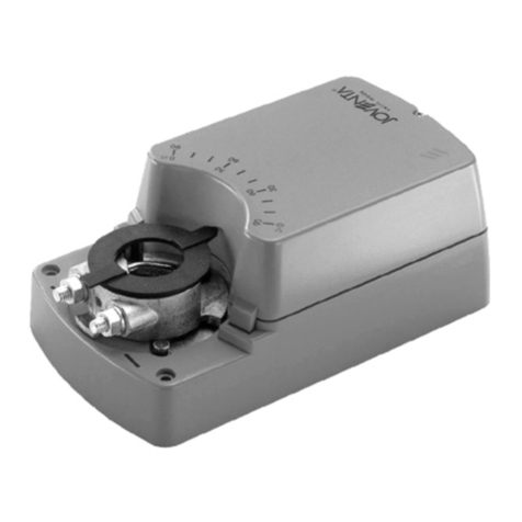
JOVENTA VA1000 Series User manual

VA1000. Ventilantrieb
Einführung
Die VA1000. Ventilantriebs- Baureihe hat eine
Kraft von 1000 N. Sie werden verwendet, um
Ventile in HVAC Systemen zu steuern. Dieser
neue Antrieb ist selbstjustierend und hat deshalb
eine sehr geringe Montage- und
Inbetriebnahmezeit. Alle Antriebe haben
mechanische Handausrastung und sind in 24VAC,
230VAC 3-Punkt sowie stetiger Regelfunktion
erhältlich. Die Ventilantriebe VA1000. sind für die
Johnson Flansch- Ventilbaureihen VG9000 PN6 &
PN10, sowie für die Baureihen VG8000 PN16 und
die Schraubventile VGS800N PN16 vorgesehen.
Mit diesem Antrieb sind maximale Schließdrücke
dieser Ventilbaureihen gesichert. Alle Antriebe sind
selbstjustierend und haben einen Hub von 7 mm
bis 49 mm.
Adaptionen auf andere Ventilbaureihen auf
Anfrage.
VA1000.
Vorteile
selbstjustierend
kürzere Inbetriebnahmezeiten
Force controlled motor shut-off.
Ensures that the maximum thrust has been
achieved.
Manual override as standard.
Allows manual positioning independent of the
power supply on all models.
Unique swing-gate yoke.
Allows lateral mounting of the actuator reducing
the vertical space over the valve needed for
installation.
IP54 enclosure protection.
Allows installation in a wide range of
environments.
Delivered with fitted 1.5 m cable.
Saves time and protects actuator during
installation.
Status LED.
Visual actuator status monitoring.
Models with optional aux. switches or 2 kΩ
feedback potentiometer.
Provides potential free contacts for user
availability or independent monitoring of the
actuator’s status.
Control-Signal failure - stem to pre-determined
position.
Actuator pre-set position after a control signal
failure (extended/retracted), is selectable in-situ.
Stroke position indicator.
Automatic adjustment of stroke indicators at the
start of the first cycle.

2 VA1000.
Bestellinformation
Code No.
Spannung
Threaded coupler
Floating Control
VA1000.2
230 V AC
VA1000.1
24 V AC
VA1000.1S
24 V AC, 2 Aux. switches
VA1000.1P2
24 V AC, 2k Feedback pot.
Proportional Control
VA1000.1M
24 V AC
0(2)…10 V DC
or 0(4)… 20 mA
VA1000.1MS
24 V AC 2 Aux. switches
0(2)…10 V DC
or 0(4)… 20 mA
Clamp coupler
Floating Control
VA1000.2
230 V AC
VA1000.1
24 V AC
VA1000.1S
24 V AC, 2 aux. switches
VA1000.1P2
24 V AC, 2k Feedback pot.
Proportional Control
VA1000.1M
24 V AC
0(2)…10 V DC
or 0(4)… 20 mA
VA1000.1MS
24 V AC 2 Aux. switches
0(2)…10 V DC
or 0(4)… 20 mA
Bestellbeispiel
Das Ventil und der Antrieb werden separate
bestellt, Wenn die Montage im Werk gewünscht
ist, wird der Bestellcode zusätzlich mit einem +M
versehen.
Beispiel :
Produkt 1 VGS8F1W1N (Ventilkörper)
Produkt 2 VA1000.1 (Antrieb)
Alternative mit Zusammenbau im Werk:
Produkt 1 VGS8F1W1N (Ventilkörper)
Produkt 2 VA1000.1+M (Antrieb)
Actuator / valve combinations
The VA1000. with threaded coupler can be
combined with the following valve range:
VG1000 series
PN 16 Female and male threaded valves
VG1
T
SS Trim DN 15...50
Brass trim DN 25...50
The VA1000. with clamp coupler can be
combined with the following valve ranges:
VGS8… Series
PN 16 Male threaded valves
VGS8
W1N
Mixing DN 15... 50
VG9000 series
PN 6 and PN 10 Flanged valves
VG9
S
1
K
All body types DN 15...50
VG9
S
1
L
All body types DN 15…50
VG8000 series
PN 16 flanged valves
VG82
V1N
2-way PDTC (NO)
DN 15…40
VG88
V1N
3-way mixing
DN 15…40
VG82
S1N
2-way PDTC (NO)
DN 15…40
VG88
S1N
3-way mixing
DN 15…40
VG89
S1N
3-way diverting
DN 15…40
PN 25 flanged valves
VG82
S1H
2-way PDTC (NO)
DN 15…40
VG88
S1H
3-way mixing
DN 15…40
VG89
S1H
3-way diverting
DN 15…40

VA1000. 3
Operation
Floating models
Connections
Actuator Stem
1-2
Extends
1-3
Retracts
No stroke adjustment is necessary due to the
automatic force control.
Feedback output 0÷2 kΩ - Fig. A
The factory setting is 50 Ω - 100 Ω when the stem
is fully retracted.
To change the setting, the feedback signal is
adjusted with the plastic knurled knob shown in
figure A below.
▪ Move the valve stem to the fully extended
position and adjust potentiometer until 20-40 Ω
can be read on ohmmeter (terminal 22 and 21
in the wiring diagram).
▪ Move the valve stem to the fully retracted
position and read the potentiometer value.
▪ Calculate the average resistance value.
▪ Move the valve stem to centre stroke position
and adjust the potentiometer to the calculated
average resistance value.
Auxiliary Switch settings
The auxiliary switches can be set by adjusting the
cams seen in figure B.
Proportional models
(0(2)…10 VDC or 0(4)…20 mA)
The VA1000. provides a proportional stroke
corresponding to the control signal.
Following control signals are defined as standard:
0…10 V DC
2…10 V DC
0…20 mA
4…20 mA
Action
(DIP switch set)
Input
control
signal
Actuator
Stem
position at
control-signal
failure *
Direct (DA)
Increases
Decreases
Extends
Retracts
Selectable*
Selectable*
Reverse (RA)
Increases
Decreases
Retracts
Extends
Selectable*
Selectable*
* "Control signal failure" position pre-set does not
operate when 0…20 mA control is selected.
The action mode, DA (direct acting) and RA
(reverse acting) is set through the DIP switches
(see paragraph "DIP switch settings" on page 5).
The actuator control signal has a buffer zone, at
each end of the span, of 0.3 V (0.6 mA). This
ensures definite valve close-off.
0%
100%
M
0 0.3 V 9.7V
100%
0.6mA 19.4mA
= Buffer zone
0%
100%
M
0100%
0.3 V 9.7V
0.6mA 19.4mA
Note: When ever the actuator is newly placed on
a valve, auto-calibration must be carried out.
Control signal
Direct acting (DA)
Control signal
Reverse acting (RA)
Knurled knob
Cam for aux.
switch No.1
Cam for aux.
switch No.2
Fig. B
Fig. A

4 VA1000.
Control signal failure pre-set position
(not functional with 0…20 mA control selected)
A control-signal failure on proportional models will
cause the actuator to automatically move the stem
to a (via DIP-switch) pre-selected position
(100% extended or 100% retracted).
Auto Calibration - Preset Signal Ranges
(DIP SWITCH 3 = OFF)
To change the Factory Default parameters the
control input signal parameters can be selected by
means of a DIP switch (see “DIP switch setting” on
page 5). The standard control signals are selected
by setting DIP switches 2, 3 and 4 (see “DIP
switch settings” on page 5).
It is recommended that the desired actuator control
signal and action be set before fitting to the valve.
Power must be connected before the auto-
calibration cycle can be started. The LED is
illuminated green when the power is ON.
Procedure:
Condition: Actuator already mounted on valve.
To start the auto calibration cycle push and hold
the button for at least 3 seconds (see figure C).
The LED flashes rapidly during the entire
procedure. The actuator will make one full cycle to
detect the stem extended and retracted limits. The
end stroke indicators are automatically placed at
the stroke limits. When the procedure ends, the
actuator switches back to its operating mode and
reaches the position corresponding to the input
signal value. The LED shows steady green when
the position is reached.
If the control-signal changes the actuator stem will
move to the new position. During stem movement
the LED flashes green.
DIP switc hes
1 to 8
Push button
Fig. C
Auto Calibration - Custom Signal Ranges
(DIP SWITCH 3 = ON)
(Max range limits 0…10 V DC or 0…20 mA)
Procedure:
Condition: Actuator already mounted on valve.
To start the auto calibration cycle push and hold
the button for at least 3 seconds (see figure C).
The LED flashes rapidly during the entire
procedure. The actuator will make one full cycle to
detect the stem extended and retracted limits. The
end stroke indicators are automatically placed at
the stroke limits. The actuator will make a full cycle
to detect the stem extended and retracted limits
and the end stroke indicators automatically pushed
to the stroke limits. Enter the desired signal range
while the actuator performs the auto calibration.
Enter the desired parameters as follows:
Set the Minimum input signal (start-point),
which can be from 0…6 V DC (0…12 mA) and
confirm by pressing the button (see figure C).
LED illuminates a steady green for 2 sec.
indicating correct entry.
If the LED illuminates a steady yellow for 2 sec.,
an incorrect setting is indicated and must be re-
entered.
Set the Maximum input signal, which can be
from 3…10 V DC (6…20 mA) and confirm by
pressing the button (span min. = 3 V DC or
6 mA).
LED illuminates a steady green for 2 sec.
indicating correct entry.
If the LED illuminates a steady yellow for 2 sec.,
an incorrect setting is indicated and must be re-
entered.
The Maximum input signal is the control span plus
the minimum input signal (start-point).
It is only possible to make one correction after
which the actuator will leave the calibration
cycle.
After making the correcting entry and confirming,
the LED will illuminate green steadily for 2 sec. to
indicate correct setting. If the LED illuminates a
steady yellow for 2 sec. this indicates that the
second entry is also erroneous and the calibration
cycle will automatically abort. To restart the auto
calibration cycle, push and hold the button for at
least 3 seconds and repeat the procedure from the
beginning.
When the procedure is finished the actuator
returns to its operating mode, reaching the position
corresponding to the input signal value, the LED
will illuminate a steady green.
If the control-signal changes the actuator stem will
move to the new position. During the stem
movement the LED flashes green.
Position feedback
The position feedback signal is 0…10 V DC or
2…10 V DC signal and could feed an external
supervisory system.
VA1000. 5
Manual override
When the crank is pushed into the hexagonal
opening power is interrupted and manual operation
is engaged. Turning the hand crank clockwise
extends the stem and counter-clockwise retracts
the stem. Pushing the hand crank down again
disengages the manual operation and reconnects
the power.
DIP switches settings
(Proportional models only)
DIP
switch
Description
Status
1
Control
ON
= 3/2 point 4 wires
OFF
= Proportional
2
Input signal
ON
= Current
OFF
= Voltage
3
Input signal
range
ON
= Custom
OFF
= Pre-set
4
ON
2…10V
4…20 mA
OFF
0…10V
0…20 mA
5
Action
ON
= Reverse Action
OFF
= Direct Action
6
Pre-set signal-
fail position*
ON
= Extended
OFF
= Retracted
7
Stroke time
ON
= 3s/mm
OFF
= 6s/mm
8
Not used
-
-
Note: * Does not operate with 0…20 mA control.
Normal operating mode
The actuator position is shown by the end stroke
indicators on the yoke.
The LED flashes green while the actuator is
moving.
The LED illuminates a steady green when the
actuator is at rest.
Actuator status indication
The actuator microprocessor carries out a failure
diagnosis when a failure has been detected. The
actuator status is indicated by the LED. When the
microprocessor detects that the stem has come to
an unexpected stop it initiates a retry cycle, this is
repeated three times and if unsuccessful the
actuator status switches to fault mode, the LED
flashes yellow and the feedback signal is no longer
reliable. If the problem is cleared actuator
continues normal function.
LED warnings
LED colour
Status
Red
Green
Yellow
On
Generic fault
Power on, motor
at rest
Indicates
2nd incorrect
custom setting
For 2s
confirming
correct entry
during custom
setting
For 2s indicating
1st incorrect
custom setting
NA for 3p/2p
NA for 3p/2p
Off
Power off
Flashing
High
temperature.
Motor running
Auto calibration
required.
Feedback not
reliable
Temporary fault
Temporary
until
temperature is
OK then LED
goes green
Flashing
quickly
Calibrating
Input signal
failure
3p/2p: Feedback
Calibrating only
NA for 3p/2p
The actuator leaves the generic fault mode by
pressing the button at least 5 seconds and the
error previously detected has been resolved
Feedback output
Input Signal
Feedback Output
0…10V DC or 0… 20 mA
0…10 V DC
2... 10V DC or 4... 20 mA
2... 10 V DC
Action depending on DIP switch-settings.
Auxiliary Switches setting
The auxiliary switches can be adjusted by means
of the aux. switch cams (see below)

6 VA1000.
Actuators without built-in positioner for
controllers with PAT (Positioning Adjusting
Time) output in parallel operation
All actuators have the same nominal running
speed (rate of travel), see specifications.
The number of actuators that can be linked to a
single controller depends on the controller’s active
power in relation to the actuators power
consumption.
Actuators with built-in positioner for
controllers with 0…10V output in parallel
operation
Actuator 1 Actuator 2 Actuator 3
The controller 0…10 V output can operate several
actuators with built-in electronic positioner.
The number of actuators that can be linked to a
single controller depends on the controller’s active
power in relation to the actuators power
consumption.
Each positioner has its own adjustment for the
starting point. Each actuator can have a different
input. Each positioner can be switched for direct or
reverse action (see DIP switch on page 5)
Mounting instructions
When mounting the actuator on a valve, please
follow the instructions below:
It is recommended that the valves be mounted
upright or at angles not greater than 90° in an
easily accessible location.
Do not cover with insulating material.
Sufficient clearance must be allowed for
actuator wiring and commissioning (refer to the
dimension drawings on page 10).
The valve must be installed so that the plug
seats against the flow, as indicated by the
arrows on the valve.
Wiring instructions
All wiring must be in accordance with local
regulations and national electrical codes and
should be carried out by authorised personnel
only.
Make sure that the line power supply is in
accordance with the power supply specified on
the device.
See also the instructions in paragraph
“Application”.
WARNING
Shock Hazard
Disconnect the power supply before wiring
connections are made to prevent personal
injury.
Equipment Damage Hazard
Make and check all wiring connections before
applying power to the system. Short circuited
or improperly connected wires may result in
permanent damage to the unit.
Note: These actuators are intended to control equipment under normal operating conditions. Where
failure or malfunction of the actuator could lead to an abnormal operating condition that could cause
personal injury or damage to the equipment or other property, other devices (limit or safety controls) or
systems (alarm or supervisory systems) intended to warn of or protect against failure or malfunction of the
actuator must be incorporated into and maintained as part of the control system.
To further actuators
24 V AC
Com
24 V AC
Retracted
24 V AC
Extended
24 V AC Com
24VAC Retracted
24VAC Extended
1
2
3
1
2
3
1
2
3
Actuator 1
Actuator 2
Actuator 3
24 VAC Com 0-10 V
0-10 V
Com
24 VAC
2 1 3 2 1 3 2 1 3
Applications: Parallel and sequential operation

VA1000. 7
Wiring Diagrams
Actuators are delivered with a fitted 1.5 m long cable. The cable numbering corresponds to the actuator
terminal numbering as seen in the wiring diagram.
Floating Models
L L
2
Red
3
Orange
N
L
1
Black
VA1000.2 230 V
VA1000.1 24 V
L L
2
Red
3
Orange
N
L
1
Black
21
23
22
2 kΩ
Output
VA1000.1P2
24 V
L L
2
Red
3
Orange
N
L
Black/Red
VA1000.1S
Aux. switch 1
output
Aux. switch 2
output
23
22
21
26
25
24
24 V
Com
Com
NO
NC
NO
NC
L L
2
Brown
3
Orange
N
L
1
Blue
Black/Grey
Black/Blue
1
Black
White/Red
White /Grey
White /Blue
Black/Blue
Black/Red
Black/Grey

8 VA1000.
Wiring Diagrams
Actuators are delivered with a fitted 1.5 m long cable. The cable numbering corresponds to the actuator
terminal numbering as seen in the wiring diagram
Proportional Models
Re-wiring for floating or On/Off function must be carried out on-site by the user.
Wired as floating
Wired as On/Off
pcb
1
Black
(Com)
3V
Grey
N
L
2
Red
VA1000.1MS
Aux. switch 1
output
Aux. switch 2
output
1
not
wired
4
Orange
3A
not
wired
23
Black/
Red
22
Black/
Blue
21
Black/
Grey
24 V
Com
Com
NO
NC
NO
NC
24
White/
Grey
26
White/
Red
25
White/
Blue
Max. 1.5 mm²
Com
0... 10 V DC
0... 20 mA
0... 10 V DC
1
Black
3V
Grey
N
L
2
Red
1
not
wired
4
Orange
3A
not
wired
24 V
Com
0... 10 V DC
0... 20 mA
0... 10 V DC
pcb
VA1000.1M
1
3V
N
L
2
1
4
3A
24 V
Com
L L
0... 10 V DC
1
3V
N
L
2
1
4
3A
24 V
Com
L L
0... 10 V DC
WARNING
For 0(4)…20 mA control the grey wire must be moved from the 3V
terminal to the 3A terminal!

VA1000. 9
Dimensions (in mm)
M16, 3.5...10 mmØ
Cable length1.5 m

10 VA1000.
Specifications
Product
VA1000.
Models
Floating
Proportional
Supply voltage
230 V ± 15 %
50/60 Hz
24 V (19…30 V)
50/60 Hz
24 V (19…30 V)
50/60 Hz
Control signal
Positioner adjustment time (PAT)
0…10 V DC or 0… 20 mA
–
2…10 V DC or 4…20 mA
Power consumption
3 W (6s/mm)
2.5 W (6s/mm)
4.5 W (3s/mm)
3.5 W (6s/mm)
VA rating
8 VA
3 VA
6 VA
Impedance
-
100kΩ min. @ 0(2)…10V,
120Ω @ 0(4)…20mA
Feedback signal
2 mA max. @ 0(2) VDC – 10 VDC, 5 kΩ min. load
Manual override
Standard
Thrust
1000N ± 20%
Stroke
7 mm – 25 mm
Nominal stroke timing :
6s/mm ± 10%
6s/mm ± 10%, 3s/mm ± 10% selectable
Enclosure protection
IP54
Protection class
230 V with cable = I ; 24 V = III
Noise pollution
35 dB(A) @ 6s/mm; 45 dB(A) @ 3s/mm
Materials:
Gearbox & yoke
Die cast aluminium
Cover
Resin ABS/PC – UL94-V0
Stem
Stainless steel
Coupler
Brass
Ambient Operating Condition
-5°C – 55°C, 10% – 90% RH non-condensing
Ambient Storage Condition
-40°C – 80°C, 5% – 95% RH non-condensing
Wiring
1.5m cable length (0.75 mm²) halogen free components attached per 1.5 mm2
terminal
Wiring entrance
M16 cable conduit adapters
Net weight
1.7 kg
Life time
Tested for 250,000 full cycles
Compliance
EMC directive 89/336 EEC: EN 61000-6-2, EN 61000-6-3
Low voltage directive 73/23 EEC: EN 60730-1
The performance specifications are nominal and conform to acceptable industry standards. For application at conditions beyond
these specifications, consult the local Joventa office. Joventa shall not be liable for damages resulting from misapplication or
misuse of its products.
This manual suits for next models
6
Table of contents
Other JOVENTA Controllers manuals

JOVENTA
JOVENTA SILENCE User manual

JOVENTA
JOVENTA DAF.10 Series User manual

JOVENTA
JOVENTA DAB1.4 Series User manual

JOVENTA
JOVENTA DMG1.1 User manual

JOVENTA
JOVENTA DMS1.1 User manual

JOVENTA
JOVENTA DMS2.5 User manual

JOVENTA
JOVENTA MM1.1 User manual

JOVENTA
JOVENTA BMF1.08 User manual

JOVENTA
JOVENTA BMS1.1 User manual

JOVENTA
JOVENTA BAS Series User manual