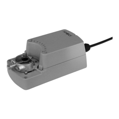
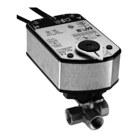
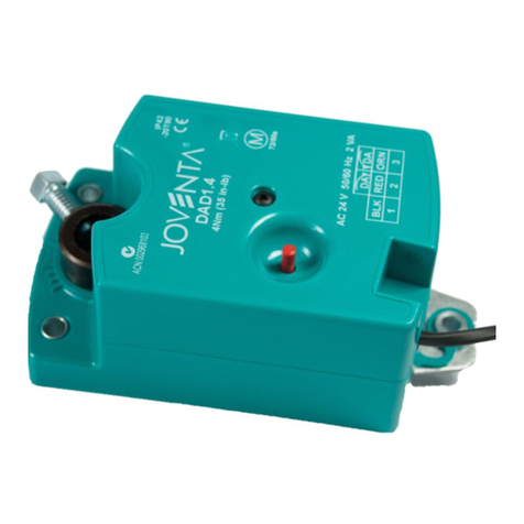
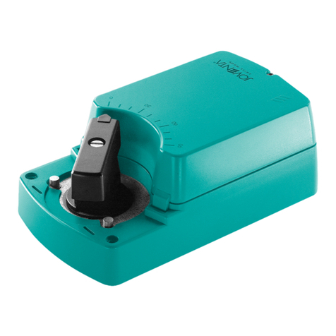
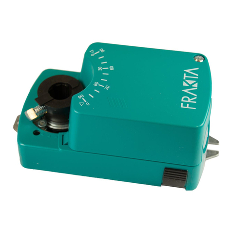
JOVENTA BAS Series User manual

JV_BAS / BMS_01 2022
■Automatic Signal Input Detection model On/Off, Floating and Proportional
Increase availability at distributors. Simplify retrofit.
■High speed actuator model
Allow applications in loop that require a quick response time.
■Optional Auxiliary Switch & potentiometer feedback
Provides line voltage capable single Pole Double-Throw (SPDT) switch and 140Ω, 1KΩ, 2KΩ or 10KΩ feedback
potentiometric.
■Direct-Coupled Design
Requires no separate linkage because they are ready for direct attachment to Johnson Controls JVx05 Series valves
by driving one captive screw.
■Rugged IP54 Rated Enclosure
Provides a high degree of protection from dust, splashing water and rough handling.
■Electronic Stall Detection
Protects from overload at all angles of rotation. The actuator may be stalled anywhere in its rotation range without the
need for mechanical end switches.
■Microprocessor-controlled Brushless DC Motor
Provides constant runtime independent of torque and increases life cycle by reducing wear.
The New Series Electric Non Spring Return
Actuators are used to provide accurate positioning
on Joventa®JVx05 Series DN15 up to DN50
ball valves in Heating, Ventilating and
Air Conditioning (HVAC) applications from 8 to 35 Nm
rated torque.
BAS / BMS
Non Spring Return Actuators for Ball Valves
Product Bulletin

JV_BAS / BMS_01 2022
2
Installation
Install the ball valve with the actuator at or above the center line of the horizontal piping.
WARNING: In steam applications, install the valve with
the stem horizontal to the piping.
Failure to follow this precaution may shorten the life of the
actuator.
WARNING: Do not install or use this actuator in or near
environments where corrosive substances or vapors
could be present.
Exposure of the actuator to corrosive environments may
damage the device's internal components, and will void
the warranty.
Mounting the actuator Inline to the Valve
1. Make sure the valve stem is inline to the valve Openings.
A C
A C
B
2. Verify that the actuator handle is inline to the actuator.
0
50
100
3. Place the actuator inline into the valve.
4. Tighten the actuator handle to the valve.

JV_BAS / BMS_01 2022
3
1. Loosen but do not remove the screw that holds the
actuator to the valve.
2. Remove the actuator from the valve.
3. Press and hold the gear release.
The actuator should be against the internal CCW stop.
4. Lift the handle out of the actuator and rotate 90°
counterclockwise.
B
A
90°
5. Reinsert the handle perpendicular into the actuator and
tighten the handle screw.
C
Mounting the Actuator Perpendicular to the Valve

JV_BAS / BMS_01 2022
4
M9000-561 Thermal Barrier
The Thermal barrier optional kit extends the application of these actuators in combination with JVx05 ball valves. Linking
together valve and actuator using the M9000-561 you can include applications with low pressure steam up to
123 °C at 103kPa (250 °F at 15 psig) and hot water up to 140 °C (284 °F).

JV_BAS / BMS_01 2022
5
1
2
DA Not
used
Not
used
RA
LED
DA 0-10
RA 2-10
Enter/
Autocal
Span Adj.
Offset Adj.
INC. DA 0-10
RA 2-10
Enter/
Autocal
LED
LED
LED
Accessing the DIP Switches
Locate the oval cover on the front of the unit and pull the cover outward. See installation sheet for further information, DIP
switches and LEDs meaning.
Automatic Signal Input Detection model
BMS1.10, BMS1.20 and BMS1.35-1 Actuator operate with 24 VAC/DC to provide 10, 20 and 35 Nm rated torque. The
actuators can be used with on/off, floating, or proportional controllers in HVAC systems that are controlled by an electronic
controller or positioner.
When the Actuators work in proportional mode, the actuator responds to 0 to 10 VDC or 2 to 10 VDC control signals. With
the addition of a 500 ohm resistor, the actuator responds to a 0 to 20 mA or 4 to 20 mA signal. A 0 to 10 VDC or 2 to 10
VDC feedback signal indicates position.
DIP Switches Settings
Command Signal Feedback Signal Setting User Interface
0 to 10 VDC
Direct
0 to 10 VDC
DA 0-10
RA 2-10
100%
10V
0%
0V 5V 12V
Flow
Set Point
24 VAC
Floating or ON/OFF
0 to 10 VDC
Reverse
0 to 10 VDC
DA 0-10
RA 2-10
10V
0V 5V 12V
100%
0%
Flow
Set Point
24 VAC
Floating or ON/OFF
2 to 10 VDC
Direct
2 to 10 VDC
DA 0-10
RA 2-10
10V
0V 2V 5V 12V
100%
0%
Flow
Set Point
24 VAC
Floating or ON/OFF
2 to 10 VDC
Reverse
2 to 10 VDC
DA 0-10
RA 2-10
10V
0V 2V 5V 12V
100%
0%
Flow
Set Point
24 VAC
Floating or ON/OFF
Auto Calibration Mode
The actuator enters auto calibration mode and positions the coupler to the maximum and minimum end stops to identify
the range of travel. To complete the auto calibration process, press Enter/Autocal until all three LEDs are on.
Remove
the oval cover
BMS1.xx
DIP Switches
and LEDs Placement
BMS2.xx
DIP Switches
and LEDs Placement
BASx.xx
DIP Switches
and LEDs Placement

JV_BAS / BMS_01 2022
6
Setting the SPAN and OFFSET Proportional Command Signal to Other Values
The actuator has the possibility to adjust the input signal changing the working range and the starting point of the signal.
The valid Offset values are 0 to 10 VDC and the valid Span values are 2 to 10 VDC. Adjusting span and offset the
feedback voltage of the actuator is automatically set as 2-10 VDC.
10V
0V 5V
Offset Span
12V
Set Point
100%
0%
Flow
1. Connect a digital multimeter between the orange (feedback) and black (common) wires. See Wiring for more wiring
information.
2. Press Enter/Autocal.
Note: To adjust the span and offset, press but not hold Enter/Autocal.
Holding Enter/Autocal for longer than three seconds triggers an autocal.
The Offset Adj. LED turns on, and the multimeter displays the current offset value.
3. Press INC.
The Offset Adj. LED flashes. The voltage reading on the multimeter increases 0.5 VDC each time you press the button.
Press INC. until you reach the desired voltage.
Once you press INC., if no further action is required, the Offset Adj. LED stops flashing after 10 seconds. The actuator
exits the program mode and the original offset value remains unchanged.
4. Press Enter/Autocal.
The Offset Adj. LED turns off indicating that the desired Offset Adj. value was recorded. The Span Adj. turns on, and the
multimeter displays the present SPAN value.
5. Press INC.
The Span Adj. LED flashes. The voltage reading on the multimeter increases by 0.5 VDC each time you press the
button. Press INC. until you reach the desired voltage.
Once you press INC., if no further action is required, the Offset and Adj. LED stops flashing after 10 seconds. The
actuator exits the program mode and the original offset value remains unchanged.
6. Press Enter/Autocal.
The Span Adj. LED turns off indicating that the desired Span Adj. setting is recored, and the actuator exits the program
mode.
Reading the SPAN and OFFSET Proportional Command Signal Voltage Settings
1. Connect a digital multimeter between the orange (feedback) and black (common) wires. See Wiring for more wiring
information.
2. Press Enter/Autocal.
The Offset Adj. LED turns on, and the multimeter displays the current offset value.
IMPORTANT: Do not press INC. Otherwise your observed offset voltage setting will change.
3. Press Enter/Autocal.
The Offset Adj. LED turns off, the Span Adj. LED turns on, and the multimeter displays the present SPAN value.
IMPORTANT: Do not press INC. Otherwise your observed SPAN voltage setting will change.
4. Press Enter/Autocal.
The Span Adj. LED turns off.
Clearing the SPAN and OFFSET Proportional Command Signal Voltage Setting
Cycle DIP switch two between 2 to 10 and 0 to 10. The active setting is the final state of DIP switch two.
Example
Command
Signal
Feedback
Signal
Setting User Interface
Offset = 5
Span = 7
Active
2 - 10 VDC
DA 0-10
RA 2-10

JV_BAS / BMS_01 2022
7
Line voltage models and High Speed models (ON/OFF and Floating)
The BAS2.xx operates with AC 100 to 240 V (AC 85 to 264 V). The actuator is design to be used with ON/OFF or
Floating controls in HVAC systems.
The BAS1.08Z and BAS1.16Z operate with 24 V DC/AC.
DIP Switch Settings
Command Signal Setting User Interface
Reverse
DA Not
used
Not
used
RA
LED
Direct
DA Not
used
RA
LED
Not
used
Ordering Informations
Code Torque
(Nm)
Running
Time (s) Controls Signal Supply Voltage
BAS1.08Z 8 8 ON/OFF and Floating 24V AC/DC
BAS2.08Z 8 8 ON/OFF and Floating 100 to 240 VAC
BAS2.10 10 35 ON/OFF and Floating 100 to 240 VAC
BMS2.10 10 35 Proportional 100 to 240 VAC
BMS1.10 10 35 ON/OFF, Floating and Proportional 24V AC/DC
BAS1.16Z* 16 16 ON/OFF and Floating 24V AC/DC
BAS2.16Z* 16 16 ON/OFF and Floating 100 to 240 VAC
BAS2.20 20 90 ON/OFF and Floating 100 to 240 VAC
BMS2.20 20 90 Proportional 100 to 240 VAC
BMS1.20 20 90 ON/OFF, Floating and Proportional 24V AC/DC
BAS2.35 35 150 ON/OFF and Floating 100 to 240 VAC
BMS2.35 35 150 Proportional 100 to 240 VAC
BMS1.35 35 150 ON/OFF, Floating and Proportional 24V AC/DC
*: Excluded from use along with JVx05 Ball Valve Series

JV_BAS / BMS_01 2022
8
Technical Specications
BASx.08Z
Product Code BAS1.08Z BAS2.08Z
Control Type On/Off, Floating
Power AC 24 V ±20%, 50/60 Hz: 12.7 VA
DC 24 V ±10%: 6.5 W
Nominal AC
230 V,
50/60 Hz:0.08 A
Transformer ≥13 VA ---
Input 24 VAC ±20%, 24 VDC ±10% 100...240 VAC (AC 85...264 V) at 50/60 Hz
Impedance 100k ohm 315k ohm
Feedback ---
Torque 8 Nm
Rotation Range 90°
Rotation Time 8s
Cycles 60,000 full stroke cycles; 1,500,000 repositions
Audible Noise <52 dBA at 0 to 8 Nm load, at a distance of 1 m
Electrical
Connections
120 in. (3.05 m) UL 444 type CMP plenum rated cable
with 19 AWG (0.75 mm2) conductors
and 0.25 in.(6 mm) ferrule ends
1.2 m (48 in.) Halogen Free Cable with 0.82 mm2 (18
AWG) conductors and 6 mm (0.25 in.)
ferrule ends
Ambient
Conditions
Operating: -30 to 60°C, 95% RH, noncondensing
Storage: -40 to 85°C, 95% RH, noncondensing
Enclosure IP54
Shipping Weight 0.9 kg
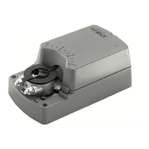
BxSx.10
Product Code BAS2.10 BMS2.10 BMS1.10
Control Type On/Off, Floating Proportional On/Off, Floating Proportional
Power Nominal AC 230 V,
50/60 Hz: 0.03 A
Nominal AC 230 V,
50/60 Hz: 0.05 A 24 V ±20%, 50/60 Hz. 6.2 VA 24 VDC ±10%, 1.9 W
Transformer --- ≥6.5 VA
Input 100...240 VAC (AC
85...264 V) at 50/60 Hz
0(2)...10 VDC,
0(4)...20 mA with field
furnished 500 ohm resistor,
Offset: 0...10 VDC,
Span: 2...10 VDC
24 VAC ±20%, 24 VDC
±10%
0(2)...10 VDC,
0(4)...20 mA with field
furnished 500 ohm resistor,
Offset: 0...10 VDC,
Span: 2...10 VDC
Impedance 315k ohm Voltage control: 100 kΩ
Current control: 0.5 kΩ 100k ohm Voltage Control: 100 kΩ
Current Control: 0.5 kΩ
Feedback --- 0(2)...10 VDC --- 0(2)...10 VDC
Torque 10 Nm
Rotation Range 90°
Rotation Time 35s
Cycles 100,000 full stroke cycles; 2,500,000 repositions
Audible Noise <35 dBA at 0 to 10 Nm load, at a distance of 1 m
Electrincal
Connections 1.2 m (48 in.) Halogen Free Cable with 0.82 mm2 (18 AWG) conductors and 6 mm (0.25 in.) ferrule ends
Ambient
Conditions
Operating: -30 to 60°C, 95% RH, noncondensing
Storage: -40 to 85°C, 95% RH, noncondensing
Enclosure IP54
Shipping Weight 0.9 kg

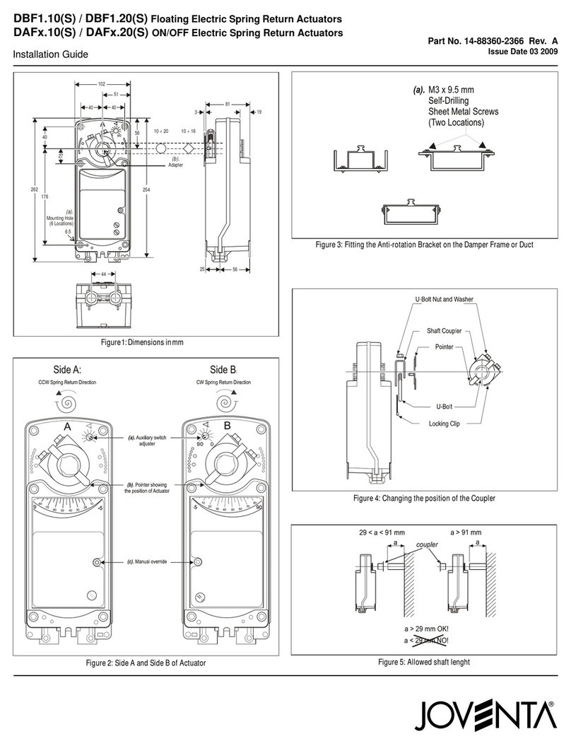
JV_BAS / BMS_01 2022
9
Technical Specications
BASx.16Z
Product Code BAS1.16Z BAS2.16Z
Control Type On/Off, Floating
Power AC 24 V ±20%, 50/60 Hz: 11.6 VA
DC 24 V ±10%: 5.4 W
Nominal AC 230 V,
50/60 Hz: 0.07 A
Transformer ≥13 VA --
Input 24 VAC ±20%, 24 VDC ±10% 100...240 VAC (AC 85...264 V) at 50/60 Hz
Impedance 100k ohm 315k ohm
Feedback --
Torque 16 Nm
Rotation Range 90°
Rotation Time 16s
Cycles 60,000 full stroke cycles; 1,500,000 repositions
Audible Noise <52 dBA at 0 to 16 Nm load, at a distance of 1 m
Electrical
Connections
120 in. (3.05 m) UL 444 type CMP plenum rated cable
with 19 AWG (0.75 mm2) conductors and 0.25 in.
(6 mm) ferrule ends
1.2 m (48 in.) Halogen Free Cable with 0.82 mm2
(18 AWG) conductors and 6 mm (0.25 in.) ferrule ends
Ambient
Conditions
Operating: -30 to 60°C, 95% RH, noncondensing
Storage: -40 to 85°C, 95% RH, noncondensing
Enclosure IP54
Shipping Weight 0.9 kg
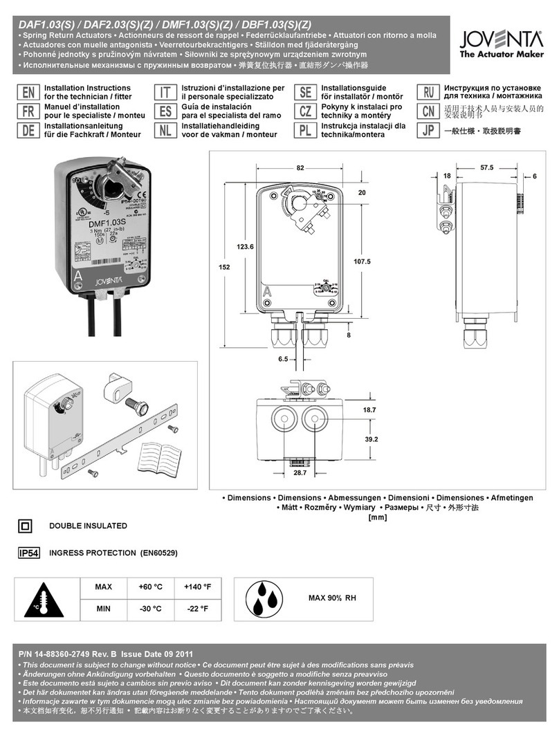
BxSx.20
Product Code BAS2.20 BMS2.20 BMS1.20
Control Type On/Off, Floating Proportional On/Off, Floating Proportional
Power Nominal AC 230 V,
50/60 Hz: 0.04 A
Nominal AC 230 V,
50/60 Hz: 0.04 A 24 V ±20%, 50/60 Hz. 6.2 VA 24 VDC ±10%, 1.9 W
Transformer --- ≥6.5 VA
Input
100...240 VAC
(AC 85...264 V)
at 50/60 Hz
0(2)...10 VDC,
0(4)...20 mA with field
furnished 500 ohm resistor,
Offset: 0...10 VDC,
Span: 2...10 VDC
24 VAC ±20%,
24 VDC ±10%
0(2)...10 VDC,
0(4)...20 mA with field
furnished 500 ohm resistor,
Offset: 0...10 VDC,
Span: 2...10 VDC
Impedance 315k ohm Voltage Control: 100 kΩ
Current Control: 0.5 kΩ 100k ohm Voltage Control: 100 kΩ
Current Control: 0.5 kΩ
Feedback -- 0(2)…10 VDC -- 0(2)...10 VDC
Torque 20 Nm
Rotation Range 90°
Rotation Time 90s
Cycles 100,000 full stroke cycles; 2,500,000 repositions
Audible Noise <45 dBA at 0 to 20 Nm load, at a distance of 1 m
Electrincal
Connections 1.2 m (48 in.) Halogen Free Cable with 0.82 mm2 (18 AWG) conductors and 6 mm (0.25 in.) ferrule ends
Ambient
Conditions
Operating: -30 to 60°C, 95% RH, noncondensing
Storage: -40 to 85°C, 95% RH, noncondensing
Enclosure IP54
Shipping Weight 0.9 kg
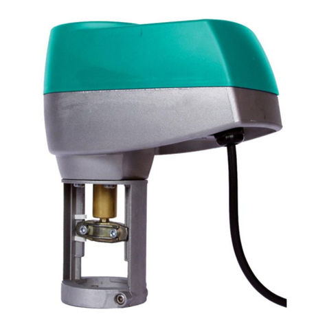
JV_BAS / BMS_01 2022
10
Technical Specications
BxSx.35
Product Code BAS2.35 BMS2.35 BMS1.35
Control Type On/Off, Floating Proportional On/Off, Floating Proportional
Power Nominal AC 230 V,
50/60 Hz: 0.04 A
Nominal AC 230 V,
50/60 Hz: 0.04 A 24 V ±20%, 50/60 Hz. 6.2 VA 24 VDC ±10%, 1.9 W
Transformer --- ≥6.5 VA
Input
100...240 VAC
(AC 85...264 V)
at 50/60 Hz
0(2)...10 VDC,
0(4)...20 mA with field
furnished 500 ohm resistor,
Offset: 0...10 VDC,
Span: 2...10 VDC
24 VAC ±20%,
24 VDC ±10%
0(2)...10 VDC,
0(4)...20 mA with field
furnished 500 ohm resistor,
Offset: 0...10 VDC,
Span: 2...10 VDC
Impedance 315k ohm Voltage Control: 100 kΩ
Current Control: 0.5 kΩ 100k ohm Voltage Control: 100 kΩ
Current Control: 0.5 kΩ
Feedback -- 0(2)…10 VDC -- 0(2)...10 VDC
Torque 35 Nm
Rotation Range 90°
Rotation Time 150s
Cycles 30,000 full stroke cycles; 750,000 repositions
Audible Noise <45 dBA at 0 to 35 Nm load, at a distance of 1 m
Electrincal
Connections 1.2 m (48 in.) Halogen Free Cable with 0.82 mm2 (18 AWG) conductors and 6 mm (0.25 in.) ferrule ends
Ambient
Conditions
Operating: -30 to 60°C, 95% RH, noncondensing
Storage: -40 to 85°C, 95% RH, noncondensing
Enclosure IP54
Shipping Weight 0.9 kg
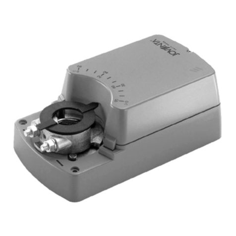
Compliance
United States:
UL Listed, CCN XAPX, File E27734; to UL 60730-1: Automatic Electrical Controls for Household and Similar Use, Part 1; and
UL 60730-2-14: Part 2, Particular Requirements for Electric Actuators. Plenum Rated (UL 2043). Suitable for use in Other
Environmental Air Space (Plenum) in accordance with section 300.22 (c) of the National Electrical Code.
Canada:
UL Listed, CCN XAPX7, File E27734; to CAN/CSA E60730-1:02: Automatic Electrical Controls for Household and Similar Use,
Part 1; and CAN/CSA-E60730-2-14, Particular Requirements for Electric Actuators.
Europe:
CE Mark – Johnson Controls declares that this product is in compliance with the essential requirements and other relevant
provisions of the EMC Directive and Low Voltage Directive.
Australia and New Zealand:
RCM, Australia/NZ Emissions Compliant

JV_BAS / BMS_01 2022
11
Dimensions
163
80.6
89
115
80
Optional Thermal Barrier

JV_BAS / BMS_01 2022
12
Accessories
The Non Spring Return Actuators for Ball Valves line has several kit and accessories that can be ordered separately and
mounted on site.
Code Number Description
M9000-342 NEMA 4X, IP66/67 Weathershield Kit for JVx05 Series Ball application of BxD, BMS1.10, BxF.03 and BxF.08 Series
Electric Actuators (quantity 1)
M9000-400 Jackshaft Linkage Adapter Kit (quantity 1)
M9000-561 Thermal Barrier Kit. Extends the BxD, BMS1.10, BxF.03 and BxF.08 Series Electric Non-Spring Return Actuators
applications to include low pressure steam (quantity 1).
M9000-606 Position indicator for Auxiliary Switches and Feedback Potentiometer Kits (quantity 5)
JOV-SW1 Auxiliary Switch Kit (one single-pole, double-throw)
JOV-SW2 Auxiliary Switch Kit (two single-pole, double-throw)
M9300-100 Threaded Conduit Adapters for 12.7 mm (1/2 in.) electrician’s fittings (quantity 5)
M9300-140 External Auxiliary Feedback Potentiometer 140 Ohm
M9300-1K External Auxiliary Feedback Potentiometer 1k Ohm
M9300-2K External Auxiliary Feedback Potentiometer 2k Ohm
M9300-10K External Auxiliary Feedback Potentiometer 10k Ohm
M9310-500 Ball Valve Linkage Kit for applying DM1.10 Series Electric Actuators to JVx05 Series Valves (quantity 1)
M9000-700 Universal ball valve linkage kit for mounting BASx.08Z and BxSx.10 actuators to other manufacturers ball valves

JV_BAS / BMS_01 2022
13
2. To remove the kit Place a screwdriver underneath the tab on each side of the actuator and firmly pull back the tab.
Auxiliary Switch & Potentiometer Feedback Kit
Mounting the kit, a connection is created between the shaft
hub of the actuator and the kit.
The position of the actuator is transferred to the gear’s kit.
1. Before mounting the kit, rotate the actuator and the kit itself counter clock wise till the end position in order to align the
holes on the coupler with the pins on the kit and snap the kit onto the BMS1.10 actuators.
2
1
3mm
1
2

JV_BAS / BMS_01 2022
Building Efciency
Headquarters: Milwaukee, Wisconsin, USA
Branch Officies: Principal Cities World-wide
Joventa®is registered trademarks of Johnson Controls
All other marks herein are the marks of their respective owners.
© Copyright 2020 Joventa. All rights reserved. Any unauthorized use or copying is strictly prohibited.
www.joventa.fr
Auxiliary switches kits
The auxiliary switches kits are used to notify starting and end position or to perform switching functions in any angular
position. The switching points can be adjust by means of a dial.
Feedback potentiometer kits
The feedback potentiometers are used as damper position indicators or as positioners for actuators operated in parallel.
Resistor Value
M9300-140 140 Ω
M9300-1K 1K Ω
M9300-2K 2K Ω
M9300-10K 10KΩ
JOV-SW1 JOV-SW2
Switch 2 (S2)
Switch 1 (S1) 1
2
This manual suits for next models
14
Table of contents
Other JOVENTA Controllers manuals

JOVENTA
JOVENTA DMS1.1 User manual

JOVENTA
JOVENTA DMG1.1 User manual

JOVENTA
JOVENTA SILENCE User manual

JOVENTA
JOVENTA MM1.1 User manual

JOVENTA
JOVENTA BMF1.08 User manual

JOVENTA
JOVENTA BMS1.1 User manual

JOVENTA
JOVENTA DAF1.03 User manual

JOVENTA
JOVENTA DAB1.4 Series User manual

JOVENTA
JOVENTA DMS2.5 User manual

JOVENTA
JOVENTA VA1000 Series User manual