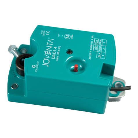
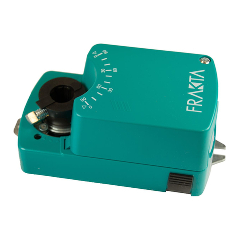
JOVENTA DAS User manual

DAS / DA / DAL
2-Point ON/OFF and 3-Point Floating Actuators
Installation Guide
English ....................................1
Français ..................................6
Deutsch ................................. 11
Italiano...................................16
Español ................................21
Nederlandse..........................26
Svenska ................................31
Česky ....................................36
P/N 14-88360-1823 Rev. B
Issue Date 10 2007

I
Figure 1: Dimensions in mm (inches)

II
Figure 2: Actuator Open

III
Figure 3: Mounting Instructions

IV
Figure 4: ON/OFF and Floating
Control
Figure 5: Parallel connection
Figure 6: Auxiliary switches Figure 7: Potentiometer

1DAS / DA / DAL
DAS / DA / DAL
2-Point ON/OFF and 3-Point Floating Actuators
Installation Guide
READ THIS INSTRUCTION SHEET AND THE SAFETY WARNINGS
CAREFULLY BEFORE INSTALLING AND SAVE IT FOR FUTURE USE
General Features
The actuators are intended for the operation of air dampers in HVAC
systems. The universal adapter allows them to be mounted directly on the
damper spindle where they are secured with the locking device supplied.
Figure 1: Dimensions in mm (inches)
a. Cover screw
Mode of operation
Figure 2: Actuator open
a. Auxiliary switch factory set at 10° (CW)
b. Auxiliary switch factory set at 80° (CW)
c. Change of direction of rotation
d. Manual button
e. Adapter for:
Round spindles: Ø 10...20 mm
Square spindles: 10...16 mm
f. 1 - Angle of rotation limiting
2- Releasing the adapter
The actuator allows ON/OFF and Floating control use, operating via
contacts. The motor stops running when the damper end-stop or actuator
end-stop is reached. For manual operation of the damper the gearing is
disengaged by means of the self-resetting button (See Figure 2 d.).
WARNING: When calculating the torque required to operate
dampers, it is essential to take info account all the data
supplied by the damper manufacturer.
P/N 14-88360-1823 Rev. B
Issue Date 10 2007

2DAS / DA / DAL
Installation and adjustment
Figure 3: Mounting Instructions
Installation
Attach the actuator to the damper spindle by means of the adapter and
secure the locking device with the screws provided.
Angle of rotation limiting
An angle-of-rotation/working range (Figure 2 f1.) of less than 90° can be
limited mechanically by repositioning the adapter in 5° steps as required.
The adapter is released by simply pressing the adapter clips on the lower
side of the actuator (Figure 2 f2.).
Selecting the direction of rotation
• In order to reverse the direction of rotation (CW/CCW), loosen screw
(See Figure 1 a.) and remove the cover.
• Reverse the motor connector (See Figure 2 c.).
• Factory setting: Clockwise (CW) rotation.
Wiring
WARNING:
• The electrical connections for the actuators must be
executed in accordance with the relevant legal requirements.
•In order to avoid any personal injury or damage to the
equipment or other property, always isolate the power
supply before commencing any work on the electrical
wiring.
• In order to avoid danger to property, it is important for the
equipment to be used solely for which it is intended.
WARNING: The integrated circuits in the actuator are
sensitive to static electricity. Take suitable precautions.

3DAS / DA / DAL
Wiring Diagrams
Figure 4: ON/OFF and Floating Control
(1) ON/OFF
(2) Floating
Figure 5: Parallel connection
(1) ON/OFF
(2) Floating
Figure 6: Auxiliary switches
(1) Auxiliary switch factory set at 10° CW
(2) Auxiliary switch factory set at 80° CW
(3) Actuator at 0°position
Figure 7: Potentiometer
Electrical connections via safety isolating transformer
• In order to make the electrical connections, loosen screw (Fig. 1 a.) and
remove the cover.
•Actuator wiring diagram according to terminal connection (Fig. 4).
•Parallel connection according to terminal connection (Fig. 5).
•Auxiliary switches according to terminal connection (Fig. 6).
•Feedback potentiometer according to terminal connection (Fig. 7).
•The electrical installation work should be carried out by a qualified
electrician.
• Wrong connections can damage the equipment. Check the connections
before energizing the power supply.
• Local accident prevention regulations should always be adhered to when
installing the actuators.
• The actuator moves about slightly while it is working so it is important to
use flexible leads for the electrical connections.

4DAS / DA / DAL
Auxiliary switches adjustment (See Figure 2 a. - b.)
Example:
Switching position adjustment a. to 30° and b. to 70°.
30°: Depress the manual button (Figure 2 d.) and rotate the adapter (Figure 2 e.)
to the 30° position. Slightly loosen the Phillips screw in the cam wheel a. so
that the wheel can be moved by hand. Rotate the cam wheel
a. counterclockwise until the switch button can be seen. Then tighten-
back the Phillips screw in the cam wheel a..
70°: Rotate the adapter (Figure 2 e.) in the same manner as before to the
70° position. Slightly loosen the Phillips screw in the cam wheel b. so that
the wheel can be moved by hand. Rotate the cam wheel b. clockwise until
the switch button can be seen. Then tighten-back the Phillips screw in the
cam wheel b..
Factory setting of auxiliary switches
The two auxiliary switches a. and b. are factory set at the to approximately
10° CW (a.) and 80° CW (b.).
Ordering Codes
Codes Descriptions
DA...1 Actuator AC/DC 24 V
DA...1.S Actuator AC/DC 24 V with 2 auxiliary switches
DA...1.P.. Actuator AC/DC 24 V with feedback potentiometer
DA...2 Actuator AC 230 V
DA...2.S Actuator AC 230 V with 2 auxiliary switches
DA...2.P.. Actuator AC 230 V with feedback potentiometer

5DAS / DA / DAL
Technical Specifications
Actuators DAS1 DA1 DAL1 DAS2 DA2 DAL2
Drive torque 8 Nm 16 Nm 24 Nm 8 Nm 16 Nm 24 Nm
Damper area 1.5 m23.0 m24.5 m21.5 m23.0 m24.5 m2
Running time 30 s 80 s 125 s 30 s 80 s 125 s
Indipendent of load, at nominal conditions and room temperature
Power supply AC 24 V ±20% / DC ±10% AC 230 V ±15%
Frequency 50-60 Hz 50-60 Hz
Power
consumption:
- operating 2.5 W 3.0 W
- at end stops 0.5 W 0.5 W
For wire sizing 5.0 VA / 2 A @ 2ms 3.6 VA / 0.1 A @ 2ms
Weight 1.1 kg 1.2 kg
Control signals ON/OFF and Floating
Position
indication
Mechanical / Potentiometer
Angle of rotation:
- Working range 90° (93° mech.)
- Limiting 5°...85° in 5° steps
Auxiliary switch
rating
3 (1.5) A, AC 230 V
Service life 60'000 cycles
Sound power
level
45 dB (A)
Protection class II
Degree of
protection
IP 54 (with cable glands, cable downwards)
Temperature:
operating/store
-20°...+50°C / -30°...+60°C
Humidity 5...95% RH (not condensing).
Maintenance Maintenance-free
Standards 89/336 EEC: EN 61000-6-2, EN 61000-6-3
72/23 EEC: EN 60730
This document is subject to change without notice

16 DAS / DA / DAL
DAS / DA / DAL
Attuatori modulanti 3 punti e ON/OFF 2 punti
Guida installazione
LEGGERE ATTENTAMENTE QUESTE ISTRUZIONI E LE AVVERTENZE
PRIMA DELL'INSTALLAZIONE E CONSERVARLE PER USO FUTURO
Funzioni generali
Gli attuatori sono progettati per il funzionamento delle serrande nei sistemi
HVAC (Heating, Ventilation and Air Conditioning). L'adattatore universale
consente il montaggio diretto degli attuatori sul perno della serranda dove
vengono fissati con il dispositivo di bloccaggio fornito.
Figura 1: Dimensioni in mm (pollici)
a. Vite coperchio
Modo di funzionamento
Figura 2: Attuatore aperto
a. Impostazione predefinita interruttore ausiliario: 10° (CW)
b. Impostazione predefinita interruttore ausiliario: 80° (CW)
c. Modifica della direzione di rotazione
d. Pulsante manuale
e. Adattatore per:
Perni rotondi: Ø 10...20 mm
Perni quadrati: 10...16 mm
f. 1 - Limitazione dell'angolo di rotazione
2- Sbloccaggio dell'adattatore
L'attuatore consente l'utilizzo del controllo ON/OFF e modulante, attraverso
l'uso di contatti. Il motore si arresta quando viene raggiunto il fine corsa
della serranda o il fine corsa dell'attuatore. Per il funzionamento manuale
della serranda, il sistema di ingranaggi viene disinnestato attraverso
l'utilizzo del pulsante di ripristino automatico (vedere la figura 2 d.).
AVVERTENZA: quando si calcola la coppia richiesta per il
funzionamento delle serrande, è necessario considerare tutti i
dati forniti dal produttore della serranda.
P/N 14-88360-1823 Rev. B
Data di pubblicazione 10 2007

17DAS / DA / DAL
Installazione e regolazione
Figura 3: Istruzioni per il montaggio
Installazione
Collegare l'attuatore al perno della serranda mediante l'adattatore e fissare
il dispositivo di bloccaggio con le viti fornite.
Limitazione dell'angolo di rotazione
È possibile limitare meccanicamente l'angolo di rotazione/intervallo di
funzionamento (figura 2 f1.) su un valore inferiore a 90° riposizionando
l'adattatore in passi di 5°, in base alle esigenze.
Per sbloccare l'adattatore, premere semplicemente i relativi fermagli nel
lato inferiore dell'attuatore (figura 2 f2.).
Selezione della direzione di rotazione
• Per invertire la direzione di rotazione (CW/CCW), allentare la vite
(vedere la figura 1 a.) e rimuovere la copertura.
• Invertire il connettore del motore (vedere la figura 2 c.).
• Impostazione predefinita: rotazione oraria (CW).
Cablaggio
AVVERTENZA:
• Eseguire i collegamenti elettrici degli attuatori rispettando le
normative legali relative.
•Per evitare lesioni personali o danni all'apparecchiatura
o altre proprietà, isolare sempre l'alimentatore prima di
iniziare qualsiasi operazione sul cablaggio elettrico.
• Per evitare danni a proprietà, è importante utilizzare
l'apparecchiatura solo per lo scopo designato.
AVVERTENZA: i circuiti integrati all'interno dell'attuatore
sono sensibili all'elettricità statica. Adottare le precauzioni del
caso.

18 DAS / DA / DAL
Schemi di cablaggio
Figura 4: Controllo ON/OFF e modulante
(1) ON/OFF
(2) Modulante
Figura 5: Connessione parallela
(1) ON/OFF
(2) Modulante
Figura 6: Interruttori ausiliari
(1) Impostazione predefinita interruttore ausiliario: 10° CW
(2) Impostazione predefinita interruttore ausiliario: 80° CW
(3) Attuatore nella posizione 0°
Figura 7: Potenziometro
Connessioni elettriche tramite trasformatore di
sicurezza
• Per eseguire le connessioni elettriche, allentare la vite (fig. 1 a.) e
rimuovere la copertura.
•Schema cablaggio attuatore in base alla connessione terminale (fig. 4).
•Connessione parallela in base alla connessione terminale (fig. 5).
•Interruttori ausiliari in base alla connessione terminale (fig. 6).
•Potenziometro di retroazione in base alla connessione terminale (fig. 7).
•Il lavoro di installazione elettrica deve essere eseguito da un
tecnico specializzato.
• Connessioni errate possono danneggiare l'apparecchiatura. Controllare
le connessioni prima di dare tensione all'alimentatore.
• Durante l'operazione di installazione degli attuatori rispettare sempre le
normative locali di prevenzione degli infortuni.
• L'attuatore si sposta leggermente durante il funzionamento, pertanto è
importante utilizzare cavetti flessibili per le connessioni elettriche.

19DAS / DA / DAL
Regolazione degli interruttori ausiliari
(vedere le figure 2 a. - b.)
Esempio:
regolazione della posizione di commutazione a. su 30° e b. su 70°.
30°: spingere il pulsante manuale (figura 2 d.) e ruotare l'adattatore (figura 2 e.)
nella posizione 30°. Allentare leggermente la vite con testa a croce
nell'eccentrico a. in modo da poter spostare l'ingranaggio manualmente.
Ruotare l'eccentrico a. in senso antiorario fino a quando l'interruttore di
accensione è visibile. Serrare nuovamente la vite con testa a croce
nell'eccentrico a..
70°: ruotare l'adattatore (figura 2 e.), come descritto in precedenza, nella
posizione 70°. Allentare leggermente la vite con testa a croce
nell'eccentrico b. in modo da poter spostare l'ingranaggio manualmente.
Ruotare l'eccentrico b. in senso orario fino a quando l'interruttore di
accensione è visibile. Serrare nuovamente la vite con testa a croce
nell'eccentrico b..
Impostazione predefinita degli interruttori ausiliari
L'impostazione predefinita dei due interruttori ausiliari a. e b. è
10° CW (a.) e 80° CW (b.).
Codici ordine
Codici Descrizioni
DA...1 Attuatore AC/DC 24 V
DA...1.S Attuatore AC/DC 24 V con 2 interruttori ausiliari
DA...1.P.. Attuatore AC/DC 24 V con potenziometro di retroazione
DA...2 Attuatore AC 230 V
DA...2.S Attuatore AC 230 V con 2 interruttori ausiliari
DA...2.P.. Attuatore AC 230 V con potenziometro di retroazione

20 DAS / DA / DAL
Specifiche tecniche
Attuatori DAS1 DA1 DAL1 DAS2 DA2 DAL2
Coppia 8 Nm 16 Nm 24 Nm 8 Nm 16 Nm 24 Nm
Sup. serranda 1,5 m23,0 m24,5 m21,5 m23,0 m24,5 m2
Tempo di esecuzione 30 s 80 s 125 s 30 s 80 s 125 s
Indipendente dal carico, in condizioni nominali e temperatura
ambiente
Alimentazione AC 24 V ±20% / DC ±10% AC 230 V ±15%
Frequenza 50-60 Hz 50-60 Hz
Consumo energetico
- funzionamento 2,5 W 3,0 W
- a fine corsa 0,5 W 0,5 W
Per dimensionamento
cavi
5,0 VA / 2 A @ 2ms 3,6 VA / 0,1 A @ 2ms
Peso 1,1 kg 1,2 kg
Segnali di controllo Controllo ON/OFF e modulante
Indicazione di
posizione
Meccanico / Potenziometro
Angolo di rotazione:
- Intervallo di
funzionamento
90° (93° mecc.)
- Limitatore 5°...85° in passi di 5°
Dati nominali
interruttore ausiliario
3 (1,5) A, AC 230 V
Vita utile 60.000 cicli
Potenza sonora 45 dB (A)
Classe di protezione II
Grado di protezione IP 54 (con pressacavi, cavo rivolto verso il basso)
Temperatura:
funzionamento/
conservazione
-20°...+50°C / -30°...+60°C
Umidità 5...95% RH (senza condensa).
Manutenzione Nessuna
Standard 89/336 EEC: EN 61000-6-2, EN 61000-6-3
72/23 EEC: EN 60730
Questo documento può essere soggetto a modifiche senza preavviso.

6DAS / DA / DAL
DAS / DA / DAL
Commandes de marche/arrêt à 2 points et
commandes flottantes à 3 points
Manuel d’installation
LISEZ ATTENTIVEMENT LES PRÉSENTES INSTRUCTIONS ET LES
CONSIGNES DE SÉCURITÉ AVANT DE PROCÉDER À
L'INSTALLATION ET CONSERVEZ-LES AUX FINS D’UTILISATION
ULTÉRIEURE
Caractéristiques générales
Les commandes sont conçues pour actionner les clapets à air de systèmes
CVC. Leur adaptateur universel permet de les monter directement sur l’axe
du clapet, auquel ils sont fixés à l’aide du dispositif de verrouillage fourni.
Figure 1: Dimensions en mm (pouces)
a. Vis de couvercle
Principe de fonctionnement
Figure 2: Commande ouverte
a. Commutateur auxiliaire réglé en usine à 10°(sens horaire)
b. Commutateur auxiliaire réglé en usine à 80° (sens horaire)
c. Changement du sens de rotation
d. Bouton manuel
e. Adaptateur pour :
Axes ronds : Ø 10...20 mm
Axes carrés : 10...16 mm
f. 1- Limitation de l’angle de rotation
2- Déverrouillage de l’adaptateur
La commande permet l’utilisation en mode marche/arrêt et commande
flottante à l’aide de contacts. Le moteur cesse de fonctionner quand la
butée mécanique est atteinte. Pour faire fonctionner manuellement le
clapet, il faut désengager l’engrenage à l’aide de la touche
d’autoréinitialisation (voir la figure 2 d.).
WARNING: Lors du calcul du couple de fonctionnement des
clapets, il faut impérativement tenir compte de toutes les
données communiquées par leur fournisseur.
P/N 14-88360-1823 Rév. B
Issue Date 10 2007

7DAS / DA / DAL
Installation et réglage
Figure 3: Instructions de montage
Installation
Fixez la commande à l’axe du clapet à l’aide de l’adaptateur et le dispositif
de verrouillage à l’aide des vis fournies.
Limitation de l’angle de rotation
Il est possible de limiter mécaniquement la plage d’angle de rotation/
fonctionnement (figure 2 f1.) à moins de 90° en repositionnant l’adaptateur
par pas de 5°, en fonction des besoins.
Pour déverrouiller l’adaptateur, appuyez sur les attaches situées dans sa
partie inférieure (figure 2 f2.).
Sélection du sens de rotation
• Pour inverser le sens de rotation (horaire/antihoraire), desserrez la vis
(voir la figure 1 a.) et déposez le couvercle.
• Inversez le connecteur du moteur (voir la figure 2 c.).
• Réglage d’usine: Rotation horaire
Câblage
WARNING:
• Le branchement électrique des commandes doit respecter
les obligations légales pertinentes.
•Pour éviter les dommages corporels ou matériels,
toujours isoler l’alimentation électrique avant
d’intervenir sur le câblage.
• Pour ne rien endommager, il est important de n’utiliser
l'équipement qu’aux fins pour lesquelles il a été conçu.
WARNING: Les circuits intégrés de la commande sont
sensibles à l'électricité statique. Prenez les précautions
requises.

8DAS / DA / DAL
Schémas de câblage
Figure 4: Commande de marche/arrêt et commande flottante
(1) Marche/arrêt
(2) Flottante
Figure 5: Branchement en parallèle
(1) Marche/arrêt
(2) FlottanteCommutateurs auxiliaires
(3) Commutateur auxiliaire réglé en usine à 10° (sens horaire)
(4) Commutateur auxiliaire réglé en usine à 80° (sens horaire)
(5) Commande en position 0°
Figure 6: Potentiomètre
Branchements électriques via un transformateur
d’isolement pour la sécurité
• Pour procéder aux branchements électriques, desserrez la vis (fig. 1 a.)
et déposez le couvercle.
•Schéma de câblage de la commande selon connexion des bornes (fig. 4).
•Branchement en parallèle selon connexion des bornes (fig. 5).
•Commutateurs auxiliaires selon connexion des bornes (fig. 6).
•Potentiomètre de feed-back selon connexion des bornes (fig. 7).
•L’installation électrique doit être confiée à un électricien qualifié.
• Une erreur de branchement peut endommager l’équipement. Vérifiez les
connexions avant de mettre l’alimentation sous tension.
• Respectez toujours les réglementations locales sur la prévention des
accidents lors de l’installation des commandes.
• La commande en fonctionnement se déplace légèrement. Il est donc
important d’utiliser des câbles flexibles pour les branchements
électriques.

9DAS / DA / DAL
Réglage des commutateurs auxiliaires
(voir la figure 2 a. - b.)
Exemple :
Réglage de la position des commutateurs a. à 30° et b. à 70°.
30°: Appuyez sur le bouton manuel (figure 2 d.) et faites tourner l’adaptateur
(figure 2 e.) jusqu'à la position 30°. Desserrez légèrement la vis cruciforme
de la roue à cames a. pour pouvoir faire bouger la roue manuellement.
Faites tourner la roue à cames a. dans le sens antihoraire jusqu’à ce que
le commutateur apparaisse. Ensuite, serrez à nouveau la vis cruciforme
dans la roue à cames a..
70°: Faites tourner l’adaptateur (figure 2 e.) comme ci-dessus jusqu’à la
position 70°. Desserrez légèrement la vis cruciforme de la roue à cames b.
pour pouvoir faire bouger la roue manuellement. Faites tourner la roue à
cames b. dans le sens horaire jusqu’à ce que le commutateur
apparaisse. Ensuite, serrez à nouveau la vis cruciforme dans la roue à
cames b..
Réglage d’usine des commutateurs auxiliaires
Les deux commutateurs auxiliaires a. et b. sont réglés en usine à environ
10° (sens horaire) (a.) et 80° (sens horaire) (b.).
Références pour la commande
Codes Description
DA...1 Commande AC/DC 24 V
DA...1.S Commande AC/DC 24 V à 2 commutateurs auxiliaires
DA...1.P.. Commande AC/DC 24 V à potentiomètre de feed-back
DA...2 Commande AC 230 V
DA...2.S Commande AC 230 V à 2 commutateurs auxiliaires
DA...2.P.. Commande AC 230 V à potentiomètre de feed-back

10 DAS / DA / DAL
Caractéristiques techniques
Commandes DAS1 DA1 DAL1 DAS2 DA2 DAL2
Couple moteur 8 Nm 16 Nm 24 Nm 8 Nm 16 Nm 24 Nm
Surface du clapet 1,5 m23,0 m24,5 m21,5 m23,0 m24,5 m2
Temps de fonctionnement 30 s 80 s 125 s 30 s 80 s 125 s
Quelle que soit la charge, à conditions nominales et température
ambiante
Alimentation électrique AC 24 V ±20% / DC ±10% AC 230 V ±15%
Fréquence 50-60 Hz 50-60 Hz
Consommation électrique:
- fonctionnement 2,5 W 3,0 W
- aux butées 0,5 W 0,5 W
Pour dimensionnement du
câble
5,0 VA / 2 A à 2 ms 3,6 VA / 0,1 A à 2 ms
Poids 1,1 kg 1,2 kg
Signaux de commande Commande de marche/arrêt et commande flottante
Indicateur de position Mécanique / Potentiomètre
Angle de rotation:
- Plage de fonctionnement 90° (93° méc.)
- Limitation 5°...85° par pas de 5°
Valeur nominale des
commutateurs auxiliaires
3 (1,5) A, AC 230 V
Durée de vie en service 60 000 cycles
Niveau sonore 45 dB (A)
Classe de protection II
Degré de protection IP 54 (avec presse-étoupe, câble vers le bas)
Température:
fonctionnement/stockage
-20°...+50°C / -30°...+60°C
Humidité 5...95 % d’humidité relative (sans condensation)
Maintenance Sans maintenance
Normes 89/336/EEC EN 61000-6-2, EN 61000-6-3
72/23 EEC: EN 60730
Ce document peut être sujet à modification sans préavis.
This manual suits for next models
2
Table of contents
Languages:
Other JOVENTA Controllers manuals

JOVENTA
JOVENTA DMF1.10 Series User manual

JOVENTA
JOVENTA DAF1.03 User manual

JOVENTA
JOVENTA SILENCE User manual

JOVENTA
JOVENTA VA1000 Series User manual

JOVENTA
JOVENTA DAB1.4 Series User manual

JOVENTA
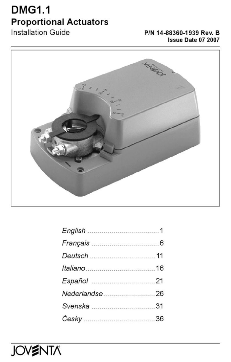
JOVENTA DMG1.1 User manual

JOVENTA
JOVENTA MM1.1 User manual
JOVENTA
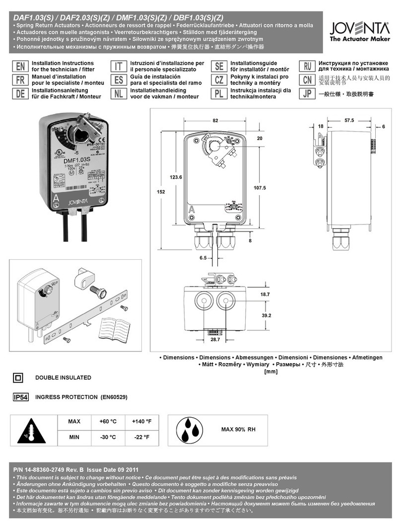
JOVENTA DAF.10 Series User manual
JOVENTA
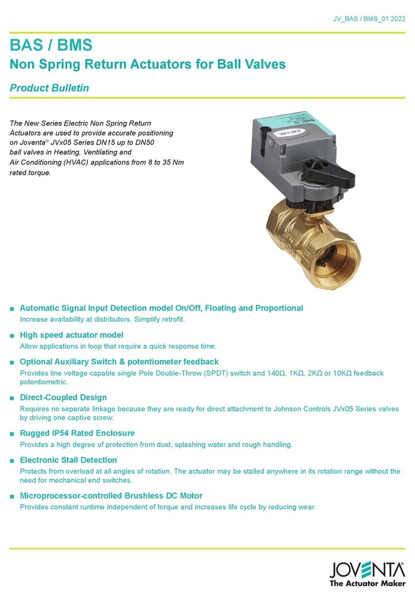
JOVENTA BAS Series User manual
JOVENTA
JOVENTA DMS1.1 User manual