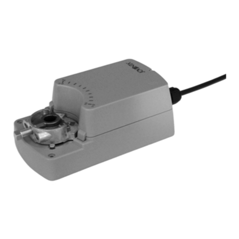
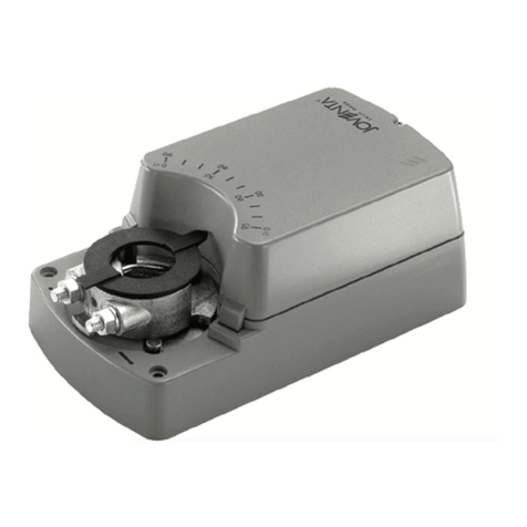
JOVENTA DMS2.5 User manual

Installation Instructions
P/N 14-88360-1947 Rev. C
Issue Date 01 2010
DMS2.5 / DM2.5 / DML2.5
Proportional Actuators
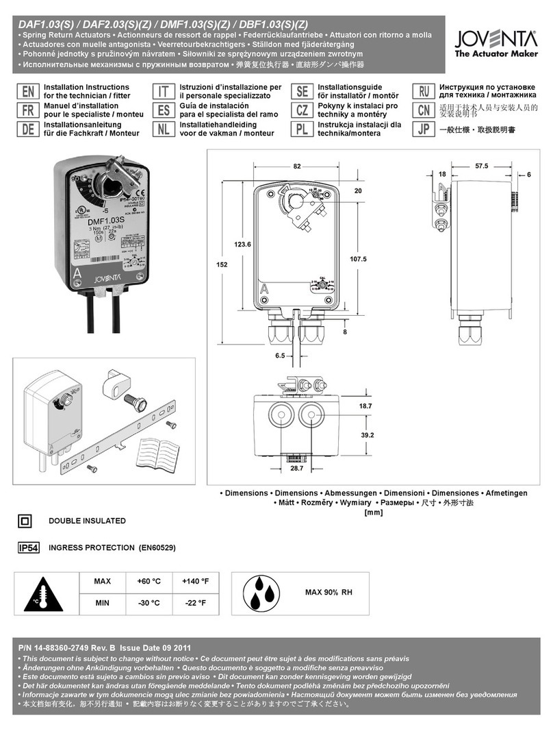
Figure 1: Dimensions (in mm)
Figure 2: Actuator open

This document is subject to change without notice
Figure 3: Mounting Instructions
Figure 4: Proportional Control Figure 5: Signal data
Figure 6: Parallel connection Figure 7: Auxiliary switches

English IS_DMS2.5 / DM2.5 / DML2.5_14-88360-1947_Rev. C_01 2010
This document is subject to change without notice 1
READ THIS INSTRUCTION SHEET AND THE SAFETY
WARNINGS CAREFULLY BEFORE INSTALLING AND
SAVE IT FOR FUTURE USE
General Features
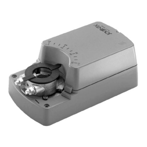
The actuators are intended for the operation of air dampers in
HVAC systems. The universal adapter allows them to be
mounted directly on the damper spindle where they are
secured with the locking device supplied.
Figure 1: Dimensions in mm
(a). Cover screw
Mode of operation
Figure 2: Actuator open
(a). Auxiliary switch factory set at 10° (CW)
(b). Auxiliary switch factory set at 80° (CW)
(c). Motor-plug
(d). Microswitch
(e). Manual button
(f). Adapter for:
Round spindles: Ø 10...20 mm
Square spindles: 10...16 mm
(g). 1- Angle of rotation limiting
2- Releasing the adapter
(h). Adjusting control signals
The actuators are controlled by a 0(4)...20 mA signal.
The motor stops running when the damper end-stop or
actuator end-stop is reached. For manual operation of the
damper the gearing is disengaged by means of the self-
resetting button (See Figure 2 e.).
Installation and adjustment
Figure 3: Mounting Instructions
Installation
Attach the actuator to the damper spindle by means of the
adapter and secure the locking device with the screws
provided.
Angle of rotation limiting
An angle-of-rotation/working range (Figure 2 g1.) of less than
90° can be limited mechanically by repositioning the adapter
in 5° steps as required.
The adapter is released by simply pressing the adapter clips
on the lower side of the actuator (Figure 2 g2.).
Selecting the direction of rotation
• In order to reverse the direction of rotation (CW/CCW),
loosen screw (See Figure 1 a.) and remove the cover.
• The direction of rotation can be reversed with the switch
(See Figure 2 d.).
• Factory setting: Clockwise (CW) rotation.
Wiring
Wiring Diagrams
Figure 4: Proportional Control
Figure 5: Signal data
(a). Microswitch
Figure 6: Parallel connection max. 5 Actuators
Figure 7: Auxiliary switches
(a). Auxiliary switch factory set at 10° CW
(b). Auxiliary switch factory set at 80° CW
(c). Actuator at 0°position
Electrical connections via safety isolating
transformer
• In order to make the electrical connections, loosen screw
(Figure 1 a.) and remove the cover.
•Actuator wiring diagram: according to terminal connection
(Figure 4).
•Parallel connection: according to terminal connection
(Figure 6).
•Auxiliary switches: according to terminal connection
(Figure 7).
•Feedback potentiometer: not possible.
•The electrical installation work should be carried out by
a qualified electrician.
• Wrong connections can damage the equipment. Check the
connections before energizing the power supply.
• Local accident prevention regulations should always be
adhered to when installing the actuators.
• The actuator moves about slightly while it is working so it is
important to use flexible leads for the electrical connections.
Auxiliary switches adjustment (See Figure 2 a. - b.)
Example:
Switching position adjustment a. to 30° and b. to 70°.
30°: Depress the manual button (Figure 2 e.) and rotate the
adapter (Figure 2 f.) to the 30° position. Slightly loosen the
Phillips screw in the cam wheel a. so that the wheel can be
moved by hand. Rotate the cam wheel a. counterclockwise
until the switch button can be seen. Then tighten-back the
Phillips screw in the cam wheel a..
WARNING: When calculating the torque
required to operate dampers, it is essential to
take info account all the data supplied by the
damper manufacturer.
WARNING:
• The electrical connections for the actuators must
be executed in accordance with the relevant legal
requirements.
•In order to avoid any personal injury or
damage to the equipment or other property,
always isolate the power supply before
commencing any work on the electrical
wiring.
• In order to avoid danger to property, it is important
for the equipment to be used solely for which it is
intended.
WARNING: The integrated circuits in the
actuator are sensitive to static electricity.
Take suitable precautions.

English IS_DMS2.5 / DM2.5 / DML2.5_14-88360-1947_Rev. C_01 2010
This document is subject to change without notice 2
70°: Rotate the adapter (Figure 2 f.) in the same manner as
before to the 70° position. Slightly loosen the Phillips screw in
the cam wheel b. so that the wheel can be moved by hand.
Rotate the cam wheel b. clockwise until the switch button can
be seen. Then tighten-back the Phillips screw in the cam
wheel b.. Factory setting of auxiliary switches.
The two auxiliary switches a. and b. are factory set at the to
approximately 10° CW (a.) and 80° CW (b.).
Ordering Codes
Codes Descriptions
DM..2.5 Actuator AC 230 V
DM..2.5S Actuator AC 230 V with 2 auxiliary switches
Technical Specifications
Actuators DMS2.5 DM2.5 DML2.5
Drive Torque 8 Nm 16 Nm 24 Nm
Damper Area 1.5 m23.0 m24.5 m2
Running Time 30...45 s 80...110 s 125...160 s
Independent of load, at nominal conditions and room temperature
Power Supply AC 230 V ±15%
Frequency 50-60 Hz
Power Consumption:
- Operating 5.5 W
- At end stops 0.6 W
For wire sizing 6.0 VA / 0.1 A @ 2ms
Weight 1.2 kg
Control Signals:
Y1 0(4)...20 mA / Ri > 100 KΩ
Y2 -
Position Signal UDC 0(2)...10 V / R > 50 KΩ
Angle of rotation:
- Working Range 90° (93° mech.)
- Limiting 5°...85° in 5° steps
Auxiliary Switch Rating 3 (1.5) A, AC 230 V
Sound Power Level 45 dB (A)
Protection Class II
Degree of Protection IP 54 (with cable glands, cable downwards)
Temperature: Operating/Store -20°...+50°C / -30°...+60°C
Humidity 5...95% RH (not condensing).
Maintenance Maintenance-free
Conformity EMC Directive 2004/108/EC:
EN 55011:2007
EN 55022:2006 A1:2007
EN 61000-3-2:2006
EN 61000-3-3:2008
EN 61000-4-2:2001
EN 61000-4-3:2006
EN 61000-4-4:2007
EN 61000-4-5:2006
EN 61000-4-6:2007
EN 61000-4-8 :1994 A1:2001
EN 61000-4-11:2004
EN 61000-6-1:2007
EN 61000-6-3:2007
Low Voltage Directive 2006/95/EC:
EN 60730-1A:2002
EN 60730-2-14:2002

Français IS_DMS2.5 / DM2.5 / DML2.5_14-88360-1947_Rev. C_01 2010
Ce document peut être sujet à des modifications sans préavis 3
LISEZ ATTENTIVEMENT LES PRÉSENTES
INSTRUCTIONS ET LES CONSIGNES DE SÉCURITÉ
AVANT DE PROCÉDER À L'INSTALLATION ET
CONSERVEZ-LES AUX FINS D’UTILISATION
ULTÉRIEURE
Caractéristiques générales
Les commandes sont conçues pour actionner les clapets à air
de systèmes CVC. Leur adaptateur universel permet de les
monter directement sur l’axe du clapet, auquel ils sont fixés à
l’aide du dispositif de verrouillage fourni.
Figure 1: Dimensions en mm
(a). Vis de couvercle
Principe de fonctionnement
Figure 2: Commande ouverte
(a). Commutateur auxiliaire réglé en usine à 10°
(sens horaire)
(b). Commutateur auxiliaire réglé en usine à 80°
(sens horaire)
(c). Prise moteur
(d). Microrupteur
(e). Bouton manuel
(f). Adaptateur pour :
Axes ronds : Ø 10...20 mm
Axes carrés : 10...16 mm
(g). 1- Limitation de l’angle de rotation
2- Déverrouillage de l’adaptateur
(h). Réglage des signaux de commande
Les commandes sont actionnées par un signal de 0(4)... 20 mA.
Le moteur cesse de fonctionner quand la butée mécanique
est atteinte. Pour faire fonctionner manuellement le clapet, il
faut désengager l’engrenage à l’aide de la touche
d’autoréinitialisation (voir la figure 2 e.).
Installation et réglage
Figure 3: Instructions de montage
Installation
Fixez la commande à l’axe du clapet à l’aide de l’adaptateur et
le dispositif de verrouillage à l’aide des vis fournies.
Limitation de l’angle de rotation
Il est possible de limiter mécaniquement la plage d’angle de
rotation/fonctionnement (figure 2 g1.) à moins de 90° en
repositionnant l’adaptateur par pas de 5°, en fonction des
besoins. Pour déverrouiller l’adaptateur, appuyez sur les
attaches situées dans sa partie inférieure (figure 2 g2.).
Sélection du sens de rotation
• Pour inverser le sens de rotation (horaire/antihoraire),
desserrez la vis (voir la figure 1 a.) et déposez le couvercle.
• Le commutateur permet d'inverser le sens de rotation (voir
la figure 2 d.).
• Réglage d’usine: Rotation horaire
Câblage
Schémas de câblage
Figure 4: Commande proportionnelle
Figure 5: Données des signaux
(a). Microrupteur
Figure 6: Branchement en parallèle 5 commandes maxi.
Figure 7: Commutateurs auxiliaires
(a). Commutateur auxiliaire réglé en usine à 10°
(sens horaire)
(b). Commutateur auxiliaire réglé en usine à 80°
(sens horaire)
(c). Commande en position 0°
Branchements électriques via un transformateur
d’isolement pour la sécurité
• Pour procéder aux branchements électriques, desserrez la
vis (fig. 1 a.) et déposez le couvercle.
•Schéma de câblage de la commande: selon connexion
des bornes (fig. 4).
•Branchement en parallèle: selon connexion des bornes (fig. 6).
•Commutateurs auxiliaires: selon connexion des bornes
(fig. 7).
•Potentiomètre de feed-back: pas possible
•L’installation électrique doit être confiée à un électricien
qualifié.
• Une erreur de branchement peut endommager
l’équipement. Vérifiez les connexions avant de mettre
l’alimentation sous tension.
• Respectez toujours les réglementations locales sur la
prévention des accidents lors de l’installation des
commandes.
• La commande en fonctionnement se déplace légèrement. Il
est donc important d’utiliser des câbles flexibles pour les
branchements électriques.
Réglage des commutateurs auxiliaires
(voir la figure 2 a. - b.)
Exemple :
Réglage de la position des commutateurs a. à 30° et b. à 70°.
30°: Appuyez sur le bouton manuel (figure 2 e.) et faites tourner
l’adaptateur (figure 2 f.) jusqu'à la position 30°. Desserrez
légèrement la vis cruciforme de la roue à cames a. pour pouvoir
faire bouger la roue manuellement. Faites tourner la roue à cames
a. dans le sens antihoraire jusqu’à ce que le commutateur
apparaisse. Ensuite, serrez à nouveau la vis cruciforme dans la
roue à cames a..
ATTENTION: Lors du calcul du couple de
fonctionnement des clapets, il faut
impérativement tenir compte de toutes les
données communiquées par leur fournisseur.
ATTENTION:
• Le branchement électrique des commandes doit
respecter les obligations légales pertinentes.
•Pour éviter les dommages corporels ou
matériels, toujours isoler l’alimentation
électrique avant d’intervenir sur le câblage.
• Pour ne rien endommager, il est important de
n’utiliser l’équipement qu’aux fins pour lesquelles
il a été conçu.
ATTENTION: Les circuits intégrés de la
commande sont sensibles à l'électricité
statique. Prenez les précautions requises.

Français IS_DMS2.5 / DM2.5 / DML2.5_14-88360-1947_Rev. C_01 2010
Ce document peut être sujet à des modifications sans préavis 4
70°: Faites tourner l’adaptateur (figure 2 f.) comme ci-dessus
jusqu’à la position 70°. Desserrez légèrement la vis cruciforme
de la roue à cames b. pour pouvoir faire bouger la roue à la
main. Faites tourner la roue à cames b. dans le sens horaire
jusqu’à ce que le commutateur apparaisse. Ensuite, serrez à
nouveau la vis cruciforme dans la roue à cames b.. Réglage
d’usine des commutateurs auxiliaires.
Les deux commutateurs auxiliaires a. et b. sont réglés en usine à
environ 10° (sens horaire) (a.) et 80° (sens horaire) (b.).
Références pour la commande
Codes Description
DM..2.5 Commande AC 230 V
DM..2.5S Commande AC 230 V à 2 commutateurs auxiliaires
Caractéristiques techniques
Commandes DMS2.5 DM2.5 DML2.5
Couple moteur 8 Nm 16 Nm 24 Nm
Surface du clapet 1,5 m23,0 m24,5 m2
Temps de fonctionnement 30...45 s 80...110 s 125...160 s
Quelle que soit la charge, à conditions nominales et température ambiante
Alimentation électrique AC 230 V ±15%
Fréquence 50-60 Hz
Consommation:
- fonctionnement 5,5 W
- aux butées 0,6 W
Pour dimensionnement du câble 6,0 VA / 0,1 A à 2 ms
Poids 1,2 kg
Signaux de commande:
Y1 0(4)...20 mA / Ri > 100 kΩ
Y2 -
Signal de position UDC 0(2)...10 V / R > 50 kΩ
Angle de rotation:
- Plage de fonctionnement 90° (93° méc.)
- Limitation 5°...85° par pas de 5°
Valeur nominale des commutateurs
auxiliaires 3 (1,5) A, AC 230 V
Niveau sonore 45 dB (A)
Classe de protection II
Degré de protection IP 54 (avec presse-étoupe, câble vers le bas)
Température : fonctionnement/
stockage -20°...+50°C / -30°...+60°C
Humidité 5...95 % d’humidité relative (sans condensation)
Maintenance Sans maintenance
Conformité Directive EMC 2004/108/EC:
EN 55011:2007
EN 55022:2006 A1:2007
EN 61000-3-2:2006
EN 61000-3-3:2008
EN 61000-4-2:2001
EN 61000-4-3:2006
EN 61000-4-4:2007
EN 61000-4-5:2006
EN 61000-4-6:2007
EN 61000-4-8 :1994 A1:2001
EN 61000-4-11:2004
EN 61000-6-1:2007
EN 61000-6-3:2007
Basse Tension 2006/95/EC:
EN 60730-1A:2002
EN 60730-2-14:2002

Deutsch IS_DMS2.5 / DM2.5 / DML2.5_14-88360-1947_Rev. C_01 2010
Änderungen ohne Ankündigung vorbehalten 5
LESEN SIE DIESE ANLEITUNG UND DIE
SICHERHEITSHINWEISE VOR DER INSTALLATION
SORGFÄLTIG DURCH UND BEWAHREN SIE SIE FÜR
SPÄTERE REFERENZZWECKE AUF
Allgemeine Merkmale
Die Stellantriebe sind für die Verstellung von Luftklappen in
Lüftungs- und Klimaanlagen entwickelt worden. Dank des
Universaladapters lassen sie sich direkt auf die Klappenachse
montieren, wo sie mit dem mitgelieferten Steck-
Schraubklemmen-Anschluss befestigt werden.
Abbildung 1: Abmessungen in mm
(a). Deckelschraube
Betriebsweise
Abbildung 2: Stellantrieb Auf
(a). Werkseitige Hilfsschalter-Einstellung auf
10° (CW)
(b). Werkseitige Hilfsschalter-Einstellung auf
80° (CW)
(c). Motorstecker
(d). Microschalter
(e). Handtaste
(f). Adapter für:
Rundachsen: Ø 10...20 mm
Vierkantachsen: 10...16 mm
(g). 1- Drehwinkel-Begrenzung
2- Adapter-Entriegelung
(h). Steuersignal-Einstellung
Die Stellantriebe werden durch ein 0(4)...20 mA Signal
angesteuert. Der Motor schaltet ab, wenn die
Klappenendstellung bzw. die Stellantriebsendstellung erreicht
ist. Zur Handverstellung der Klappe wird der Antrieb über die
Rückstelltaste ausgerastet (siehe Abbildung 2 e.).
Installation und Einstellung
Abbildung 3: Montageanweisungen
Installation
Bringen Sie den Stellantrieb mit Hilfe des Adapters an der
Klappenachse an und befestigen Sie den Steck-
Schraubklemmen-Anschluss mit den mitgelieferten
Schrauben.
Drehwinkel-Begrenzung
Ein Drehwinkel/Arbeitsbereich (Abbildung 2 g1.) von unter 90°
kann, entsprechend der Anforderungen, mechanisch durch
Umstecken des Adapters in 5°-Schritten begrenzt werden.
Das Entfernen des Adapters erfolgt durch einfaches Drücken
der Adapterklammer auf der Unterseite des Antriebes
(Abbildung 2 g2.).
Drehrichtungs-Auswahl
• Zur Änderung der Drehrichtung (CW/CCW) lösen Sie die
Schraube (siehe Abbildung 1 a.) und nehmen den Deckel ab.
• Die Drehrichtung kann über den Schalter umgekehrt werden
(siehe Abbildung 2 d.).
• Werkseinstellung: Drehung im Uhrzeigersinn (CW).
Verdrahtung
Anschlusspläne
Abbildung 4: Stetige Ansteuerung
Abbildung 5: Signalwerte
(a). Microschalter
Abbildung 6: Parallelanschluss bis max. 5 Stellantriebe
Abbildung 7: Hilfsschalter
(a). Werkseitige Hilfsschalter-Einstellung auf
10° (CW)
(b). Werkseitige Hilfsschalter-Einstellung auf
80° (CW)
(c). Stellantrieb auf 0°-Stellung
Elektrische Anschlüsse über
Sicherheitstransformator
• Zum Herstellen der elektrischen Anschlüsse, lösen Sie die
Schraube (Abbildung 1 a.) und nehmen Sie den Deckeln ab.
•Stellantrieb-Anschlussplan: gemäß Anschluss (Abbildung
4).
•Parallelanschluss: gemäß Anschluss (Abbildung 6).
•Hilfsschalter: gemäß Anschluss (Abbildung 7).
•Rückführpotentiometer: nicht möglich.
•Die elektrischen Anschlüsse dürfen nur von einem
qualifizierten Elektrofachmann hergestellt werden.
• Ein falscher Anschluss kann zur Beschädigung der
Ausrüstung führen. Überprüfen Sie die Anschlüsse, bevor
Sie die Stromversorgung einschalten.
• Bei der Installation der Stellantriebe sind stets die
einschlägigen Unfallverhütungsvorschriften einzuhalten.
• Der Stellantrieb bewegt sich während des Betriebs etwas.
Deshalb ist es wichtig, für die elektrischen Anschlüsse
flexible Leitungen zu verwenden.
Hilfsschalter-Einstellung (siehe Abbildung 2 a. - b.)
Beispiel:
Schaltpositions-Einstellung a. auf 30° und b. auf 70°.
30°: Drücken Sie die Handtaste (Abbildung 2 e.) und drehen Sie
den Adapter (Abbildung 2 f.) in die 30°-Stellung. Lösen Sie die
Phillips-Schraube des Schaltrades etwas, a. so dass sich das
Rad manuell drehen lässt. Drehen Sie das Schaltrad a. gegen
den Uhrzeigersinn, bis der Schaltknopf zu sehen ist. Ziehen
Sie daraufhin die Phillips-Schraube des Schaltrades wieder
fest a..
ACHTUNG: Bei der Berechnung des für die
Verstellung der Klappen erforderlichen
Drehmoments sind die Angaben des
Klappenherstellers zu beachten.
ACHTUNG:
• Die elektrischen Anschlüsse für die Stellantriebe
müssen entsprechend den einschlägigen
gesetzlichen Bestimmungen hergestellt werden.
•Um Personenschäden bzw. eine
Beschädigung der Ausrüstung oder
sonstigen Sachschaden zu vermeiden,
trennen Sie vor jeglichem Eingriff an der
elektrischen Verdrahtung stets die
Stromversorgung.
• Zur Vermeidung von Sachschäden darf die
Ausrüstung nur bestimmungsgemäß eingesetzt
werden.
ACHTUNG: Die im Stellantrieb integrierten
Schaltkreise reagieren empfindlich auf
elektrostatische Entladungen. Ergreifen Sie
entsprechende Vorsichtsmaßnahmen.

Deutsch IS_DMS2.5 / DM2.5 / DML2.5_14-88360-1947_Rev. C_01 2010
Änderungen ohne Ankündigung vorbehalten 6
70°: Drehen Sie den Adapter (Abbildung 2 f.) wie zuvor in die
70°-Stellung. Lösen Sie die Phillips-Schraube des Schaltrades
etwas, b. so dass sich das Rad manuell drehen lässt. Drehen
Sie das Schaltrad b. im Uhrzeigersinn, bis der Schaltknopf zu
sehen ist. Ziehen Sie daraufhin die Phillips-Schraube des
Schaltrades wieder fest b.. Werkseinstellung der Hilfsschalter.
Die zwei Hilfsschalter a. und b. sind werkseitig auf etwa
10° CW (a.) und 80° CW (b.) eingestellt.
Bestellcodes
Codes Beschreibungen
DM..2.5 Stellantrieb AC 230 V
DM..2.5S Stellantrieb AC 230 V mit 2 Hilfsschaltern
Technische Daten
Stellantriebe DMS2.5 DM2.5 DML2.5
Drehmoment 8 Nm 16 Nm 24 Nm
Klappenfläche 1,5 m23,0 m24,5 m2
Laufzeit 30...45 s 80...110 s 125...160 s
Unabhängig von der Belastung, bei Nennbedingungen und Raumtemperatur
Nennspannung AC 230 V ±15%
Frequenz 50-60 Hz
Leistungsverbrauch:
- im Betrieb 5,5 W
- in Endstellung 0,6 W
Dimensionierung 6,0 VA / 0,1 A @ 2ms
Gewicht 1,2 kg
Steuersignale:
Y1 0(4)...20 mA / Ri > 100 KΩ
Y2 -
Stellungssignal UDC 0(2)...10 V / R > 50 kΩ
Drehwinkel:
- Arbeitsbereich 90° (93° mech.)
- Begrenzung 5°...85° in 5°-Schritten
Hilfsschalter Schaltleistung 3 (1,5) A, AC 230 V
Schallpegel 45 dB (A)
Schutzklasse II
Schutzart IP 54 (mit Kabelverschraubungen, Kabel nach unten)
Umgebungsbedingungen:
Betriebstemperatur/
Lagertemperatur -20°...+50°C / -30°...+60°C
Feuchte 5...95% r.H. (nicht kondensierend).
Service Wartungsfrei
Konformität EMV-Richtlinie 2004/108/EG:
EN 55011:2007
EN 55022:2006 A1:2007
EN 61000-3-2:2006
EN 61000-3-3:2008
EN 61000-4-2:2001
EN 61000-4-3:2006
EN 61000-4-4:2007
EN 61000-4-5:2006
EN 61000-4-6:2007
EN 61000-4-8 :1994 A1:2001
EN 61000-4-11:2004
EN 61000-6-1:2007
EN 61000-6-3:2007
Niederspannungsrichtline 2006/95/EG:
EN 60730-1A:2002
EN 60730-2-14:2002

Italiano IS_DMS2.5 / DM2.5 / DML2.5_14-88360-1947_Rev. C_01 2010
Questo documento è soggetto a modifiche senza preavviso 7
LEGGERE ATTENTAMENTE QUESTE ISTRUZIONI E LE
AVVERTENZE PRIMA DELL'INSTALLAZIONE E
CONSERVARLE PER USO FUTURO
Funzioni generali
Gli attuatori sono progettati per il funzionamento delle
serrande nei sistemi HVAC (Heating, Ventilation and Air
Conditioning). L'adattatore universale consente il montaggio
diretto degli attuatori sul perno della serranda dove vengono
fissati con il dispositivo di bloccaggio fornito.
Figura 1: Dimensioni in mm
(a). Vite coperchio
Modo di funzionamento
Figura 2: Attuatore aperto
(a). Impostazione predefinita interruttore ausiliario:
10° (CW)
(b). Impostazione predefinita interruttore ausiliario:
80° (CW)
(c). Connettore motore
(d). Microinterruttore
(e). Pulsante manuale
(f). Adattatore per:
Perni rotondi: Ø 10...20 mm
Perni quadrati: 10...16 mm
(g). 1- Limitazione dell'angolo di rotazione
2- Sbloccaggio dell'adattatore
(h). Segnali di controllo di regolazione
Gli attuatori sono controllati per mezzo di un segnale 0(4)...20
mA. Il motore si arresta quando viene raggiunto il fine corsa
della serranda o il fine corsa dell'attuatore. Per il
funzionamento manuale della serranda, il sistema di
ingranaggi viene disinnestato attraverso l'utilizzo del pulsante
di ripristino automatico (vedere la figura 2 e.).
Installazione e regolazione
Figura 3: Istruzioni per il montaggio
Installazione
Collegare l'attuatore al perno della serranda mediante
l'adattatore e fissare il dispositivo di bloccaggio con le viti
fornite.
Limitazione dell'angolo di rotazione
È possibile limitare meccanicamente l'angolo di rotazione/
intervallo di funzionamento (figura 2 g1.) su un valore inferiore
a 90° riposizionando l'adattatore in passi di 5°, in base alle
esigenze. Per sbloccare l'adattatore, premere semplicemente
i relativi fermagli nel lato inferiore dell'attuatore (figura 2 g2.).
Selezione della direzione di rotazione
• Per invertire la direzione di rotazione (CW/CCW), allentare
la vite (vedere la figura 1 a.) e rimuovere la copertura.
• È possibile invertire la direzione di rotazione con
l'interruttore (vedere la figura 2 d.).
• Impostazione predefinita: rotazione oraria (CW).
Cablaggio
Schemi di cablaggio
Figura 4: Controllo proporzionale
Figura 5: Dati del segnale
(a). Microinterruttore
Figura 6: Connessione parallela max. 5 attuatori
Figura 7: Interruttori ausiliari
(a). Impostazione predefinita interruttore ausiliario:
10° CW
(b). Impostazione predefinita interruttore ausiliario:
80° CW
(c). Attuatore nella posizione 0°
Connessioni elettriche tramite trasformatore di
sicurezza
• Per eseguire le connessioni elettriche, allentare la vite
(fig. 1 a.) e rimuovere la copertura.
•Schema cablaggio attuatore: in base alla connessione
terminale (fig. 4).
•Connessione parallela: in base alla connessione terminale
(fig. 6).
•Interruttori ausiliari: in base alla connessione terminale
(fig. 7).
•Potenziometro di retroazione: non possibile.
•Il lavoro di installazione elettrica deve essere eseguito
da un tecnico specializzato.
• Connessioni errate possono danneggiare l'apparecchiatura.
Controllare le connessioni prima di dare tensione
all'alimentatore.
• Durante l'operazione di installazione degli attuatori rispettare
sempre le normative locali di prevenzione degli infortuni.
• L'attuatore si sposta leggermente durante il funzionamento,
pertanto è importante utilizzare cavetti flessibili per le
connessioni elettriche.
Regolazione degli interruttori ausiliari
(vedere le figure 2 a. - b.)
Esempio:
regolazione della posizione di commutazione a. su 30° e b. su 70°.
30°: spingere il pulsante manuale (figura 2 e.) e ruotare
l'adattatore (figura 2 f.) nella posizione 30°. Allentare
leggermente la vite con testa a croce nell'eccentrico a. in
modo da poter spostare l'ingranaggio manualmente. Ruotare
l'eccentrico a. in senso antiorario fino a quando l'interruttore
di accensione è visibile. Serrare nuovamente la vite con testa
a croce nell'eccentrico a..
AVVERTENZA: quando si calcola la coppia
richiesta per il funzionamento delle serrande, è
necessario considerare tutti i dati forniti dal
produttore della serranda.
AVVERTENZA:
• Eseguire i collegamenti elettrici degli attuatori
rispettando le normative legali relative.
•Per evitare lesioni personali o danni
all'apparecchiatura o altre proprietà, isolare
sempre l'alimentatore prima di iniziare
qualsiasi operazione sul cablaggio elettrico.
• Per evitare danni a proprietà, è importante
utilizzare l'apparecchiatura solo per lo scopo
designato.
AVVERTENZA: i circuiti integrati all'interno
dell'attuatore sono sensibili all'elettricità
statica. Adottare le precauzioni del caso.
Italiano IS_DMS2.5 / DM2.5 / DML2.5_14-88360-1947_Rev. C_01 2010
Questo documento è soggetto a modifiche senza preavviso 8
70°: Ruotare l'adattatore (figura 2 f.), come descritto in
precedenza, nella posizione 70°. Allentare leggermente la vite
con testa a croce nell'eccentrico b. in modo da poter spostare
l'ingranaggio manualmente. Ruotare l'eccentrico b. in senso
orario fino a quando l'interruttore di accensione è visibile.
Qundi serrare nuovamente la vite con testa a croce
nell'eccentrico b.. Impostazione predefinita degli interruttori
ausiliari.
L'impostazione predefinita dei due interruttori ausiliari a. e b. è
10° CW (a.) e 80° CW (b.).
Codici ordine
Codici Descrizioni
DM..2.5 Attuatore AC 230 V
DM..2.5S Attuatore AC 230 V con 2 interruttori ausiliari
Specifiche tecniche
Attuatori DMS2.5 DM2.5 DML2.5
Coppia 8 Nm 16 Nm 24 Nm
Sup. serranda 1,5 m23,0 m24,5 m2
Tempo di esecuzione 30...45 s 80...110 s 125...160 s
Indipendente dal carico, in condizioni nominali e temperatura ambiente
Alimentazione AC 230 V ±15%
Frequenza 50-60 Hz
Consumo energetico
- funzionamento 5,5 W
- a fine corsa 0,6 W
Per dimensionamento cavi 6,0 VA / 0,1 A @ 2ms
Peso 1,2 kg
Segnali di controllo:
Y1 0(4)...20 mA / Ri > 100 KΩ
Y2 -
Segnale di posizione UDC 0(2)...10 V / R > 50 KΩ
Angolo di rotazione:
- Intervallo di funzionamento 90° (93° mecc.)
- Limitazione 5°...85° in passi di 5°
Dati nominali interruttore
ausiliario 3(1,5) A, AC 230 V
Potenza sonora 45 dB (A)
Classe di protezione II
Grado di protezione IP 54 (con pressacavi, cavo rivolto verso il basso)
Temperatura: funzionamento/
conservazione -20°...+50°C / -30°...+60°C
Umidità 5...95% RH (senza condensa).
Manutenzione Nessuna
Conformità Direttiva Compatibilità Elettromagnetica
2004/108/CE:
EN 55011:2007
EN 55022:2006 A1:2007
EN 61000-3-2:2006
EN 61000-3-3:2008
EN 61000-4-2:2001
EN 61000-4-3:2006
EN 61000-4-4:2007
EN 61000-4-5:2006
EN 61000-4-6:2007
EN 61000-4-8 :1994 A1:2001
EN 61000-4-11:2004
EN 61000-6-1:2007
EN 61000-6-3:2007
Direttiva Bassa Tensione 2006/95/CE:
EN 60730-1A:2002
EN 60730-2-14:2002

Español IS_DMS2.5 / DM2.5 / DML2.5_14-88360-1947_Rev. C_01 2010
Este documento está sujeto a cambios sin previo aviso 9
ANTES DE LA INSTALACIÓN, LEA CUIDADOSAMENTE
ESTAS INSTRUCCIONES Y LAS ADVERTENCIAS DE
SEGURIDAD Y CONSÉRVELAS PARA SU USO FUTURO
Características generales
Los actuadores intervienen en el funcionamiento de los
reguladores de aire en los sistemas de calefacción,
ventilación y aire acondicionado (HVAC). El adaptador
universal permite su montaje directo sobre el eje del
regulador, asegurándolos con el dispositivo de bloqueo que
se suministra.
Figura 1: Dimensiones en mm
(a). Perno de la cubierta
Modo de funcionamiento
Figura 2: Actuador abierto
(a). Interruptor auxiliar, ajustado de fábrica a 10°
(CW)
(b). Interruptor auxiliar, ajustado de fábrica a 80°
(CW)
(c). Enchufe del motor
(d). Microinterruptor
(e). Botón manual
(f). Adaptador para:
Ejes redondos: Ø 10...20 mm
Ejes cuadrados:
10...16 mm
(g). 1- Limitación del ángulo de rotación
2- Liberación del adaptador
(h). Ajuste de señales de control
Los actuadores están controlados por una señal 0(4)...20 mA.
El funcionamiento del motor se detendrá cuando se alcance el
tope final del regulador o del actuador. En el caso del
funcionamiento manual del regulador, el engranaje se
desconecta mediante el botón de restablecimiento automático
(Véase la Figura 2 e.).
Instalación y ajuste
Figura 3: Instrucciones de montaje
Instalación
Sujete el actuador al eje del regulador mediante el adaptador
y asegure el dispositivo de bloqueo con los pernos que se
suministran.
Limitación del ángulo de rotación
Para limitar de forma mecánica un ángulo de rotación o una
gama de trabajo (Figura 2 g1.) inferior a 90°, deberá volver a
colocar el adaptador en la posición adecuada en tramos de
5°. Para liberar el adaptador sólo tiene que pulsar los clips
situados en la parte inferior del actuador (Figura 2 g2.).
Selección de la dirección de rotación
• Para cambiar la dirección de la rotación (CW (sentido de las
agujas del reloj) / CCW (sentido contrario a las agujas del
reloj)), afloje el perno (Véase la Figura 1 a.) y retire la
cubierta.
• Puede cambiar la dirección de rotación con el interruptor
(Véase la Figura 2 d.).
• Ajuste de fábrica: Rotación en el sentido de las agujas
del reloj (CW).
Cableado
Diagramas del cableado
Figura 4: Control proporcional
Figura 5: Datos de señal
(a). Microinterruptor
Figura 6: Conexión en paralelo máximo de 5 actuadores
Figura 7: Interruptores auxiliares
(a). Interruptor auxiliar, ajustado de fábrica a 10° CW
(b). Interruptor auxiliar, ajustado de fábrica a 80° CW
(c). Actuador en la posición 0°
Conexiones eléctricas a través de un
transformador aislante de seguridad
• Para realizar las conexiones eléctricas, afloje el perno
(Fig. 1 a.) y retire la cubierta.
•Diagrama de cableado del actuador: según la conexión del
terminal (Fig. 4).
•Conexión en paralelo: según la conexión del terminal (Fig. 6).
•Interruptores auxiliares: según la conexión del terminal
(Fig. 7).
•Potenciómetro de feedback: no es posible.
•Las labores de la instalación eléctrica debe realizarlas
un técnico electricista cualificado.
• Una conexión incorrecta puede dañar el equipo. Revise las
conexiones antes de volver a activar el suministro eléctrico.
• Durante la instalación de los actuadores debe aplicarse en
todo momento la normativa para la prevención de
accidentes.
• El actuador realiza pequeños movimientos durante su
funcionamiento, por lo que es importante emplear cables
flexibles en las conexiones eléctricas.
Ajuste de los interruptores auxiliares
(Véase la figura 2 a. - b.)
Ejemplo:
Ajuste de la posición de interruptores a. a 30° y b. a 70°.
30°: Pulse el botón manual (Figura 2 e.) y gire el adaptador
(Figura 2 f.) hasta la posición de 30°. Afloje ligeramente el perno
Phillips de la rueda de levas a. hasta que pueda mover
manualmente la rueda. Gire la rueda a. en el sentido contrario a
las agujas del reloj hasta que pueda ver el botón del interruptor.
A continuación, vuelva a apretar el perno Phillips de la rueda de
levas a..
ADVERTENCIA: Para calcular la torsión
necesaria para el funcionamiento de los
reguladores, es esencial tener en cuenta todos
los datos facilitados por su fabricante.
ADVERTENCIA:
• Las conexiones eléctricas de los actuadores
deberán realizarse siguiendo los requisitos
legales pertinentes.
•Para evitar daños personales, del equipo o
de propiedades de terceros, desconecte
siempre el suministro eléctrico antes de
realizar cualquier tipo de trabajo con el
cableado.
• Para evitar daños en la propiedad, es importante
que el equipo se emplee exclusivamente con el
fin para el que ha sido creado.
ADVERTENCIA: Los circuitos integrados del
actuador son sensibles a la electricidad
estática. Adopte las debidas precauciones.

Español IS_DMS2.5 / DM2.5 / DML2.5_14-88360-1947_Rev. C_01 2010
Este documento está sujeto a cambios sin previo aviso 10
70°: Gire el adaptador (Figura 2 f.) de la forma indicada
anteriormente hasta la posición de 70°. Afloje ligeramente el
perno Phillips de la rueda de levas b. hasta que pueda mover
manualmente la rueda. Gire la rueda b. en el sentido de las
agujas del reloj hasta que pueda ver el botón del interruptor.
A continuación, vuelva a apretar el perno Phillips de la rueda
de levas b.. Ajustes de fábrica de los interruptores auxiliares.
Los dos interruptores auxiliares a. y b. están ajustados de fábrica
a, aproximadamente, 10° CW (a.) y 80° CW (b.).
Códigos de pedido
Códigos Descripciones
DM..2.5 Actuador AC 230 V
DM..2.5S Actuador AC 230 V con 2 interruptores auxiliares
Especificaciones técnicas
Actuadores DMS2.5 DM2.5 DML2.5
Torque de dirección 8 Nm 16 Nm 24 Nm
Área del regulador 1,5 m23,0 m24,5 m2
Tiempo de ejecución 30...45 s 80..0,110 s 125..0,160 s
Independientemente de la carga, a temperatura ambiente y condiciones nominales
Suministro eléctrico AC 230 V ±15%
Frecuencia 50-60 Hz
Consumo energético:
- en funcionamiento 5,5 W
- en los topes 0,6 W
Para la medida del cableado 6,0 VA / 0,1 A a 2ms
Peso 1,2 kg
Señales de control:
Y1 0(4)...20 mA / Ri > 100 KΩ
Y2 -
Señal de posición UDC 0(2)...10 V / R > 50 KΩ
Ángulo de rotación:
- Gama de trabajo 90° (93° mec.)
- Limitación 5°...85° en tramos de 5°
Clasificación de interruptores
auxiliares 3(1,5) A, AC 230 V
Nivel de potencia acústica 45 dB (A)
Clase de protección II
Grado de protección IP 54 (con prensaestopas, pasacables)
Temperatura: en funcionamiento/
almacenamiento -20°...+50°C / -30°...+60°C
Humedad 5...95% HR (sin condensación).
Mantenimiento Mantenimiento gratuito
Conformidad Directiva Electromagnética
(EMC) 2004/108/EC:
EN 55011:2007
EN 55022:2006 A1:2007
EN 61000-3-2:2006
EN 61000-3-3:2008
EN 61000-4-2:2001
EN 61000-4-3:2006
EN 61000-4-4:2007
EN 61000-4-5:2006
EN 61000-4-6:2007
EN 61000-4-8 :1994 A1:2001
EN 61000-4-11:2004
EN 61000-6-1:2007
EN 61000-6-3:2007
Directiva de Bajo Voltaje 2006/95/EC:
EN 60730-1A:2002
EN 60730-2-14:2002

Nederlands IS_DMS2.5 / DM2.5 / DML2.5_14-88360-1947_Rev. C_01 2010
Dit document kan zonder kennisgeving worden gewijzigd 11
LEES DIT INSTRUCTIEBLAD EN DE
VEILIGHEIDSWAARSCHUWINGEN ZORGVULDIG
VOORDAT DE INSTALLATIE WORDT UITGEVOERD, EN
BEWAAR DIT MATERIAAL ZODAT U HET IN DE
TOEKOMST OOK NOG KUNT RAADPLEGEN
Algemene functies
De bekrachtigers zijn bedoeld voor luchtdempers in HVAC-
systemen. Met de universele adapter zijn ze direct aan te
sluiten op de demperas, waar ze worden vastgezet met de
meegeleverde vergrendeling.
Figuur 1: Afmetingen in mm
(a). Schroef van afdekking
Werking
Figuur 2: Bekrachtiger open
(a). Fabrieksinstelling van AUX-schakelaar 10°
(rechtsom)
(b). Fabrieksinstelling van AUX-schakelaar 80°
(rechtsom)
(c). Motorplug
(d). Microschakelaar
(e). Handmatig, knop
(f). Adapter voor:
ronde assen: Ø 10...20 mm
vierkante assen: 10...16 mm
(g). 1- Draaihoek begrenzend
2- De adapter ontgrendelen
(h). Regelsignalen afstellen
De bekrachtigers worden aangestuurd door een signaal van
0(4)...20 mA. De motor stopt met draaien wanneer de
eindstop van de demper of de eindstop van de bekrachtiger is
bereikt. Voor de handmatige bediening van de demper wordt
de transmissie gedeactiveerd door middel van de
zelfresetknop (zie figuur 2 e.).
Installatie en afstelling
Figuur 3: Montage-instructies
Installatie
Bevestig de bekrachtiger op de demperas door middel van de
adapter en zet de vergrendeling met de meegeleverde
schroeven vast.
Draaihoek begrenzend
Een draaihoek/werkbereik (figuur 2 g1.) van minder dan 90°
kan mechanisch worden begrensd door de adapter naar
behoefte in stappen van 5° opnieuw te positioneren.
De adapter wordt eenvoudig ontgrendeld door de
adapterbeugels aan de onderkant van de bekrachtiger in te
drukken (figuur 2 g2.).
De draairichting selecteren
• Om de draairichting om te keren (rechtsom/linksom) draait u
de schroef los (zie figuur 1 a.) en verwijdert u de afdekking.
• De draairichting kan worden omgekeerd met de schakelaar
(zie figuur 2 d.).
• Fabrieksinstelling: Rechtsom.
Bedrading
Bedradingsschema's
Figuur 4: Proportionele regeling
Figuur 5: Signaalgegevens
(a). Microschakelaar
Figuur 6: Parallelle aansluiting max. 5 bekrachtigers
Figuur 7: AUX-schakelaars
(a). Fabrieksinstelling van AUX-schakelaar 10°
rechtsom
(b). Fabrieksinstelling van AUX-schakelaar 80°
rechtsom
(c). Bekrachtiger op positie 0°
Elektrische aansluitingen via isolerende
veiligheidstransformator
• Om de elektrische aansluitingen te maken, draait u de
schroef los (figuur 1 a.) en verwijdert u de afdekking.
•Bedradingsschema voor bekrachtiger: volgens
klemaansluiting (figuur 4).
•Parallelle aansluiting: volgens klemaansluiting (figuur 6).
•AUX-schakelaars: volgens klemaansluiting (figuur 7).
•Feedbackpotentiometer: niet mogelijk.
•Het werk aan de elektrische installatie dient door een
gekwalificeerde elektricien te worden uitgevoerd.
• Verkeerde aansluitingen kunnen de apparatuur
beschadigen. Controleer de aansluitingen voordat u de
voeding inschakelt.
• Neem bij het installeren van de bekrachtigers altijd de
plaatselijke voorschriften in acht om ongevallen te
voorkomen.
• Er zit enige beweging in de bekrachtiger wanneer deze in
bedrijf is. Het gebruik van flexibele draden voor de
elektrische aansluitingen is dan ook belangrijk.
Afstelling van AUX-schakelaars (zie figuur 2 a. - b.)
Voorbeeld:
Schakelaarpositie a. op 30° en b. op 70°.
30°: Druk de knop voor handmatig in (figuur 2 e.) en draai de
adapter (figuur 2 f.) naar de positie voor 30°. Draai de
kruiskopschroef in het nokwiel a. iets los zodat het wiel
handmatig kan worden bewogen. Draai het nokwiel a.
linksom totdat u de schakelaarknop ziet. Draai de
kruiskopschroef in het nokwiel a. vervolgens weer vast.
WAARSCHUWING: Bij de berekening van het
vereiste draaimoment voor bediening van de
dempers is het van essentieel belang alle
verstrekte gegevens door de fabrikant van de
demper te gebruiken.
WAARSCHUWING:
• De elektrische aansluitingen voor de
bekrachtigers moeten in overeenstemming met
de relevante wettelijke vereisten worden
uitgevoerd.
•Om persoonlijk letsel of schade aan de
apparatuur of andere eigendommen te
voorkomen, dient u de voeding altijd te
isoleren voordat u met de elektrische
bedrading gaat werken.
• Om gevaar voor eigendommen te voorkomen, is
het van belang de apparatuur alleen te gebruiken
voor het doel waarvoor deze is bestemd.
WAARSCHUWING: De geïntegreerde circuits in
de bekrachtiger zijn gevoelig voor statische
elektriciteit. Neem afdoende
voorzorgsmaatregelen.

Nederlands IS_DMS2.5 / DM2.5 / DML2.5_14-88360-1947_Rev. C_01 2010
Dit document kan zonder kennisgeving worden gewijzigd 12
70°: Draai de adapter (figuur 2 f.) op dezelfde wijze als eerst
naar de positie voor 70°. Draai de kruiskopschroef in het
nokwiel b. iets los zodat het wiel handmatig kan worden
bewogen. Draai het nokwiel b. rechtsom totdat u de
schakelaarknop ziet. Draai de kruiskopschroef in het nokwiel
b.. vervolgens weer vast. Fabrieksinstelling van AUX-
schakelaars.
De fabrieksinstelling van de twee AUX-schakelaars a. en b.
zijn 10° rechtsom (a.) en 80° rechtsom (b.).
Bestelcodes
Codes Beschrijvingen
DM..2.5 Bekrachtiger AC 230 V
DM..2.5S Bekrachtiger AC 230 V met 2 AUX-schakelaars
Technische specificaties
Bekrachtigers DMS2.5 DM2.5 DML2.5
Aandrijfmoment 8 Nm 16 Nm 24 Nm
Dempergebied 1,5 m23,0 m24,5 m2
Looptijd 30...45 s 80..110 s 125...160 s
Onafhankelijk van belasting, bij nominale omstandigheden en ruimtetemperatuur
Voeding AC 230 V ±15%
Frequentie 50-60 Hz
Stroomverbruik:
- in bedrijf 5,5 W
- bij eindstops 0,6 W
Voor bedrading 6,0 VA / 0,1 A @ 2 ms
Gewicht 1,2 kg
Regelsignalen:
Y1 0(4)...20 mA / Re > 100 KΩ
Y2 -
Positiesignaal UDC 0(2)...10 V / R > 50 KΩ
Draaihoek:
- werkbereik 90° (93° mech.)
- begrenzend 5°...85° in stappen van 5°
Nominale waarde AUX-
schakelaar 3 (1,5) A, AC 230 V
Geluidsniveau 45 dB (A)
Beschermingsklasse II
Beschermingsgraad IP 54 (met kabelpakkingen, kabel neerwaarts)
Temperatuur: in bedrijf/opslag -20°...+50 °C / -30°...+60 °C
Vochtigheid 5...95% RV (niet-condenserend).
Onderhoud Onderhoudsvrij
Conformiteit EMC richtlijn 2004/108/EC:
EN 55011:2007
EN 55022:2006 A1:2007
EN 61000-3-2:2006
EN 61000-3-3:2008
EN 61000-4-2:2001
EN 61000-4-3:2006
EN 61000-4-4:2007
EN 61000-4-5:2006
EN 61000-4-6:2007
EN 61000-4-8 :1994 A1:2001
EN 61000-4-11:2004
EN 61000-6-1:2007
EN 61000-6-3:2007
Laagspanningsrichtlijn 2006/95/EC:
EN 60730-1A:2002
EN 60730-2-14:2002

Svenska IS_DMS2.5 / DM2.5 / DML2.5_14-88360-1947_Rev. C_01 2010
Det här dokumentet kan ändras utan föregående meddelande 13
LÄS DET HÄR INSTRUKTIONSBLADET OCH
SÄKERHETSANVISNINGARNA NOGGRANT INNAN DU
INSTALLERAR MODULEN OCH SPARA DEM FÖR
FRAMTIDA BRUK
Allmänna funktioner
Ställdonen är avsedda att styra luftfuktare i HVAC-system.
Den universella adaptern gör att ställdonen kan monteras
direkt på fuktarspindeln där de fästs med den medföljande
låsenheten.
Figur 1: Mått i mm
(a). Täckskruv
Styrningsläge
Figur 2: Ställdonet öppet
(a). Extra brytare med fabriksinställningen 10°
(medsols)
(b). Extra brytare med fabriksinställningen 80°
(medsols)
(c). Motorkontakt
(d). Microbrytare
(e). Manuell knapp
(f). Adapter för:
Runda spindlar: Ø 10...20 mm
Fyrkantiga spindlar:
10...16 mm
(g). 1- Vinkel för roteringsbegränsning
2- Frigöring av adaptern
(h). Justering av kontrollsignaler
Ställdonen styrs av en 0(4)...20 mA-signal.
Motorn stängs av när fuktarens ändstopp eller ställdonets
ändstopp har nåtts. För manuell styrning av fuktaren
inaktiveras drivningen med hjälp av den självåterställande
knappen (se figur 2 e.).
Installation och justering
Figur 3: Monteringsinstruktioner
Installation
Fäst ställdonet vid fuktarspindeln med hjälp av adaptern och
skruva fast låsenheten med de medföljande skruvarna.
Vinkel för roteringsbegränsning
En roteringsvinkel eller ett driftområde (figur 2 g1.) som är
mindre än 90° kan begränsas mekaniskt genom att adaptern
flyttas i steg om 5° efter behov.
Adaptern frigörs genom att adapterklämmorna på ställdonets
nedre sida trycks ned (figur 2 g2.).
Välja roteringsriktning
• Lossa skruven för att ändra roteringsriktningen (medsols/
motsols) (se figur 1 a.) och ta bort locket.
• Roteringsriktningen kan ändras med brytaren (se figur 2 d.).
• Fabriksinställning: Medsols rotering.
Kabeldragning
Illustration kabeldragning
Figur 4: Proportionell kontroll
Figur 5: Signaldata
(a). Microbrytare
Figur 6: Parallellanslutning max. 5 ställdon
Figur 7: Extra brytare
(a). Extra brytare med fabriksinställningen 10°
(medsols)
(b). Extra brytare med fabriksinställningen 80°
(medsols)
(c). Ställdonet i positionen 0°
Elektriska anslutningar via transformator för
säkerhetsisolering
• Gör de elektriska anslutningarna genom att lossa skruven
(figur 1 a.) och ta bort locket.
•Kopplingsschema för ställdon: enl. terminalanslutning
(figur 4).
•Parallellanslutning: enl. terminalanslutning (figur 6).
•Extra brytare: enl. terminalanslutning (figur 7).
•Feedbackkompensator: ej möjligt.
•Den elektriska installationen bör utföras av en
kvalificerad elektriker.
• Felaktiga anslutningar kan skada utrustningen. Kontrollera
anslutningarna innan strömkällan görs spänningsfri.
• Lokala regler för att förhindra olyckor bör alltid följas när
ställdonen installeras.
• Ställdonet rör sig något när det är i drift så det är viktigt att
använda mjuka kablar för de elektriska anslutningarna.
Justering av extra brytare (se figur 2 a. - b.)
Exempel:
Växla positionsjusteringen a. till 30° och b. till 70°.
30°: Tryck ned den manuella knappen (figur 2 e.) och rotera
adaptern (figur 2 f.) till positionen 30°. Lossa stjärnskruven i
kamhjulet något a. så att hjulet kan flyttas för hand. Rotera
kamhjulet a. motsols tills brytarknappen syns. Skruva sedan
fast stjärnskruven i kamhjulet igen a..
70°: Rotera adaptern (figur 2 f.) på samma sätt som tidigare till
positionen 70°. Lossa stjärnskruven i kamhjulet något b. så att
hjulet kan flyttas för hand. Rotera kamhjulet b. medsols tills
brytarknappen syns. Skruva sedan fast stjärnskruven i
kamhjulet igen b.. Fabriksinställning för extra brytare.
De två extra brytarna a. och b. är fabriksinställda på cirka
10° medsols (a.) och 80° medsols (b.).
VARNING! När vridmomentet som krävs för att
styra fuktarna beräknas är det viktigt att ta med
alla data från fuktarens tillverkare.
VARNING!
• De elektriska anslutningarna för ställdonen
måste utföras i enlighet med relevanta juridiska
krav.
•Undvik personskada och skador på
utrustningen eller annan egendom genom att
alltid isolera spänningsmatningen innan
arbete utförs på kabeldragningen.
• Det är viktigt att utrustningen endast används för
det den är avsedd för, så att skador på egendom
undviks.
VARNING! De integrerade kretsarna i ställdonet
är känsliga för statisk elektricitet. Vidta lämpliga
åtgärder.

Svenska IS_DMS2.5 / DM2.5 / DML2.5_14-88360-1947_Rev. C_01 2010
Det här dokumentet kan ändras utan föregående meddelande 14
Beställningskoder
Koder Beskrivning
DM..2.5 Ställdon AC 230 V
DM..2.5S Ställdon AC 230 V med två extra brytare
Tekniska specifikationer
Ställdon DMS2.5 DM2.5 DML2.5
Drivmoment 8 Nm 16 Nm 24 Nm
Fuktarområde 1,5 m23,0 m24,5 m2
Drifttid 30...45 s 80...110 s 125...160 s
Oberoende av belastning, vid nominella förhållanden och rumstemperatur
Spänningsmatning AC 230 V ±15%
Frekvens 50–60 Hz
Strömförbrukning:
- i drift 5,5 W
- vid ändstopp 0,6 W
För ledningsstorlek 6,0 VA / 0,1 A @ 2 ms
Vikt 1,2 kg
Kontrollsignaler:
Y1 0(4)...20 mA / Ri > 100 KΩ
Y2 -
Positionssignal UDC 0(2)...10 V / R > 50 KΩ
Roteringsvinkel:
- Driftområde 90° (93° mek.)
- Begränsning 5°...85° i steg om 5°
Klassificering för extra brytare 3(1,5) A, AC 230 V
Ljudnivå 45 dB (A)
Skyddsklass II
Skyddsgrad IP 54 (med packboxar, kabel nedåt)
Temperatur: drift/förvaring -20°...+50 °C / -30°...+60 °C
Fuktighet 5...95 % RH (utan kondens).
Underhåll Underhållsfritt
Överensstämmelse elektromagnetisk kompatibilitet direktiv
2004/108/EC:
EN 55011:2007
EN 55022:2006 A1:2007
EN 61000-3-2:2006
EN 61000-3-3:2008
EN 61000-4-2:2001
EN 61000-4-3:2006
EN 61000-4-4:2007
EN 61000-4-5:2006
EN 61000-4-6:2007
EN 61000-4-8 :1994 A1:2001
EN 61000-4-11:2004
EN 61000-6-1:2007
EN 61000-6-3:2007
elektrisk utrustning avsedd för
användning inom vissa
spänningsgränser directiv 2006/95/EC:
EN 60730-1A:2002
EN 60730-2-14:2002

Česky IS_DMS2.5 / DM2.5 / DML2.5_14-88360-1947_Rev. C_01 2010
Tento dokument podléhá změnám bez předchozího upozornění 15
PŘED INSTALACÍ SI POZORNĚPŘEČTĚTE TYTO
POKYNY A BEZPEČNOSTNÍ VAROVÁNÍ A USCHOVEJTE
JE PRO POZDĚJŠÍ POUŽITÍ
Obecné funkce
Spouštěče jsou určeny pro řízení regulačních vzduchových
ventilův klimatizačních systémech. Univerzální adaptér
umožňuje jejich montáž přímo na hřídel ventilu, kde jsou
zajištěny pomocí dodávaného zajišt’ovacího mechanismu.
Obrázek 1: Rozměry v mm
(a). Šroub pro připevnění krytu
Provozní režim
Obrázek 2: Rozebraný spouštěč
(a). Pomocný spínačje továrněnastaven na 10°
(doprava)
(b). Pomocný spínačje továrněnastaven na 80°
(doprava)
(c). Konektor motoru
(d). Mikrospínač
(e). Manuální tlačítko
(f). Adaptér pro:
Oblé hřídele: Ř10...20 mm
Čtyřhranné hřídele: Ř10 ...16 mm
(g). 1– Omezení úhlu otočení
2– Uvolnění adaptéru
(h). Nastavení vstupních signálů
Spouštěče jsou řízeny signálem 0(4)...20 mA.
Motor se zastaví, jakmile bude dosažena koncová poloha
ventilu nebo spouštěče. V případěmanuálního ovládání
ventilu se pohon vypne pomocí samočinněresetovaného
tlačítka (Viz obrázek 2 e.).
Instalace a nastavení
Obrázek 3: Montážní pokyny
Instalace
Připevněte pomocí adaptéru spouštěč k hřídeli ventilu a
zajistěte pojistný mechanismus pomocí dodávaných šroubů.
Omezení úhlu otočení
Úhel otočení nebo pracovní rozsah (obrázek 2 g1.) v úhlu
menším než 90° mohou být podle potřeby omezeny
mechanicky změnou polohy adaptéru v krocích po 5°.
Adaptér lze uvolnit jednoduchým stisknutím lamel adaptéru ve
spodní části spouštěče (obrázek 2 g2.).
Výběr směru otáčení
• Pokud chcete změnit směr otáčení (doleva nebo doprava),
uvolněte šroub (viz obrázek 1 a.) a sejměte kryt.
•Směr otáčení lze přepnout pomocí přepínače (Viz obrázek 2 d.).
• Tovární nastavení: Otáčení doprava.
Zapojení
Schémata zapojení
Obrázek 4: Proporcionální řízení
Obrázek 5: Parametry signálu
(a). Mikrospínač
Obrázek 6: Paralelní zapojení – max. 5 spouštěčů
Obrázek 7: Pomocné spínače
(a). Pomocný spínačje továrněnastaven na 10°
(doprava)
(b). Pomocný spínačje továrněnastaven na 80°
(doprava)
(c). Spouštěč v poloze 0°
Elektrické zapojení s využitím bezpečnostního
izolačního transformátoru
• Chcete-li vytvořit elektronické zapojení, uvolněte šroub
(obrázek 1 a.) a sejměte kryt.
•Schéma zapojení spouštěče: zapojení svorky acc.
(obrázek 4).
•Paralelní zapojení: zapojení svorky acc. (obrázek 6).
•Pomocné spínače: zapojení svorky acc.(obrázek 7).
•Potenciometr zpětné vazby: nelze použít.
•Instalaci elektrického vedení by měla provádět školená
osoba.
• Nesprávné zapojení může způsobit poškození zařízení.
Před zapnutím napájecího zdroje zkontrolujte zapojení.
•Při instalaci spouštěčů vždy dodržujte místní směrnice
bezpečnostní práce.
• Spouštěč se při provozu mírněpohybuje, a proto je důležité,
aby se při zapojení použily ohebné vodiče.
Nastavení pomocných spínačů (viz obrázek 2 a. – b.)
Příklad:
Nastavení spínací polohy a. nejvýše 30° a b. nejvýše 70°.
30°: Stiskněte manuální tlačítko (obrázek 2 e.) a otočte adaptér
(obrázek 2 f.) do polohy 30°. Mírněpovolte křížový šroub
vačkového kola a., aby bylo možné kolem pohybovat ručně.
Otáčejte vačkovým kolem a. doleva, dokud nebude vidět
tlačítko spínače. Opět utáhněte křížový šroub vačkového kola a..
70°: Otočte adaptérem (obrázek 2 f.) stejným způsobem jako
předtím, do polohy 70°. Mírněpovolte křížový šroub
vačkového kola b., aby bylo možné kolem pohybovat ručně.
Otáčejte vačkovým kolem b. doprava, dokud nebude vidět
tlačítko spínače. Opět utáhněte křížový šroub vačkového kola
b.. Tovární nastavení pomocných spínačů.
Dva pomocné spínače a. a b. jsou továrněnastavené na
zhruba 10° doprava (a.) a 80° doprava (b.).
VAROVÁNÍ: Při vypočítávání kroutícího
momentu potřebného pro ovládání ventilůje
potřeba vzít v úvahu veškeré údaje
poskytované výrobcem ventilu.
VAROVÁNÍ:
• Elektrické připojení spouštěčů musí být
provedeno v souladu se související vyhláškou.
•Aby se zabránilo zranění osob nebo
poškození vybavení nebo jiného majetku,
vždy izolujte odpojte zdroj předtím, než
budete provádět práci na elektrickém vedení.
• Aby se zabránilo škodám na majetku, je důležité,
aby toto vybavení bylo používáno pouze k
účelům, pro které je určeno.
VAROVÁNÍ: Integrované obvody ve spouštěči
jsou citlivé na statický proud. Učiňte proto
příslušná opatření.

Česky IS_DMS2.5 / DM2.5 / DML2.5_14-88360-1947_Rev. C_01 2010
Tento dokument podléhá změnám bez předchozího upozornění 16
Objednací kódy
Kódy Popis
DM..2.5 Spouštěč 230 V STŘ.
DM..2.5S Spouštěč 230 V STŘ. s 2 pomocnými spínači
Technické údaje
SpouštěčeDMS2.5 DM2.5 DML2.5
Kroutící moment motoru 8 Nm 16 Nm 24 Nm
Plocha ventilu 1,5 m23,0 m24,5 m2
Provozní doba 30 až 45 s 80 až 110 s 125 až 160 s
Zařízení je nezávislé na zatížení, nominálních podmínkách a pokojové teplotě
Napájecí zdroj 230 V STŘ. ±15%
Frekvence 50–60 Hz
Spotřeba energie:
– v provozu 5,5 W
– v koncových polohách 0,6 W
Kapacita vodičů 6,0 VA / 0,1 A @ 2ms
Hmotnost 1,2 kg
Řídící signály:
Y1 0(4) ...20 mA / Ri > 100 kΩ
Y2 -
Signál polohy U0(2)...10 V SS. / R > 50 kΩ
Úhel otočení:
– Pracovní rozsah 90° (93° mech.)
– Omezení 5°...85° v krocích po 5°
Jmenovité hodnoty
pomocného spínače3 (1,5) A, 230 V STŘ.
Úroveňintenzity zvuku 45 dB (A)
Třída ochrany II
Stupeňochrany IP 54 (kabelové spojky, kabel veden směrem dolů)
Teplota: provozní/skladovací -20°...+50°C / -30°...+60°C
Vlhkost 5...95% RV (nekondenzující)
Údržba bez údržby
Shody Směrnice EMC 2004/108/EC:
EN 55011:2007
EN 55022:2006 A1:2007
EN 61000-3-2:2006
EN 61000-3-3:2008
EN 61000-4-2:2001
EN 61000-4-3:2006
EN 61000-4-4:2007
EN 61000-4-5:2006
EN 61000-4-6:2007
EN 61000-4-8 :1994 A1:2001
EN 61000-4-11:2004
EN 61000-6-1:2007
EN 61000-6-3:2007
Směrnice pro nízkonapět’ová zařízení
2006/95/EC:
EN 60730-1A:2002
EN 60730-2-14:2002
This manual suits for next models
2
Table of contents
Languages:
Other JOVENTA Controllers manuals

JOVENTA
JOVENTA BMF1.08 User manual

JOVENTA
JOVENTA DAS User manual

JOVENTA
JOVENTA MM1.1 User manual

JOVENTA
JOVENTA DAF1.03 User manual

JOVENTA
JOVENTA BMS1.1 User manual

JOVENTA
JOVENTA DMS1.1 User manual

JOVENTA
JOVENTA SILENCE User manual

JOVENTA
JOVENTA DAF.10 Series User manual

JOVENTA
JOVENTA DAB1.4 Series User manual

JOVENTA
JOVENTA DMF1.10 Series User manual
Popular Controllers manuals by other brands

RMG
RMG DFAWLC-044 installation manual

New Focus
New Focus Picomotor 8742 quick start guide

Siemens
Siemens IP Controller N350E Technical product information

Crestron
Crestron onCue BPC-8 Supplemental guide

Mitsubishi Electric
Mitsubishi Electric ANS-Q-LARGE-U user manual

AUMA
AUMA SGM 04.1 Operation instructions