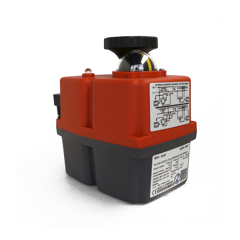
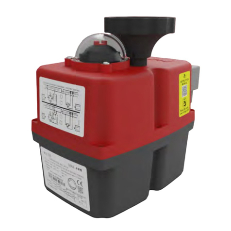
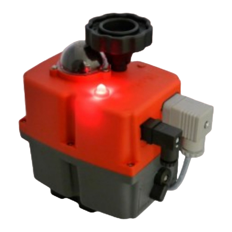
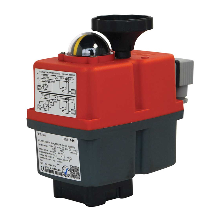
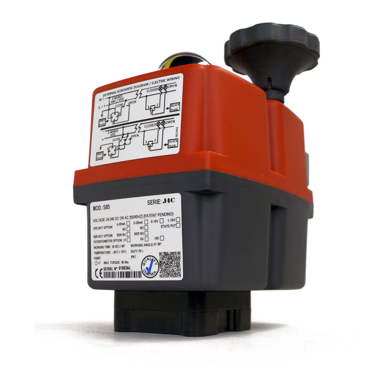
J+J J2 L/H 10 User manual

for
J+J Quarter Turn Actuators
Manual
ManualManual
Tel.: +49 5181 6017 | info@juj-deutschland.de | www.juj-deutschland.de

®
©by J+J Deutschland GmbH
®
For this documentation the J+J Deutschland GmbH claims author's legal protection.
This documentation may not be extended without previous written agreement of the company J+J
Deutschland GmbH, neither amended, multiplied nor transmitted for use to third party. To the
demandofthesedocuments,please,addressJ+JDeutschlandGmbH.
This documentation may not be extended without previous written agreement of the company J
+J DeutschlandGmbH,neitheramended,multipliednortransmittedforusetothirdparty.
Ausgabedatum: 03/2017
Subject to technical changes.
Imprint

Introduction.................................................................4
Generaladvise...............................................................5
Returnconsignment...........................................................5
Safetynotes ................................................................6
Devicedescription............................................................8
ModelOverview...........................................................9
Partdescription..........................................................10
Typelabel..............................................................11
StatusLED .............................................................13
Emergencymanualoverride................................................14
Installation.................................................................15
Environmentalconditions..................................................15
Maintenance............................................................15
Mountingofthevalve.....................................................16
Alternation multi flange plate in model 10 and 20. . . . . . . . . . . . . . . . . . . . . . . . . . . . . . . . 18
Conversiondoublesquareadapter...........................................19
ElectricalInstallation.........................................................20
PositionAdjustment..........................................................22
JumperConfiguration ........................................................26
FAQ`s.....................................................................27
Special models
ActuatorswithBSR-BatterySpringReturn.......................................29
ActuatorswithDPSPositioner..................................................31
AlignmentofDPSpositioner................................................31
Adjustworkingangel......................................................32
FunctionsofstatusLEDs ..................................................33
FAQ`s.................................................................34
Actuatorswithpotentiometer...................................................35
3positionsactuators.........................................................36
Actuatorswith2phasescontrol.................................................37
Appendix
Technicaldata..............................................................39
Currentconsumption ........................................................40
Wiringdiagrams.............................................................42
Dimensionaldrawings........................................................46
Index

Dear customer,dearassembleranduser
thesemountingandoperatingmanualapplytoallJ+JElectricalPartTurnActuatorsoftheseriesJ2,
J3, J3C. It should provide information and knowledge for you to execute the assembly and
instalation.Payattentionparticularlytothesecurityindications.
The actuators are designed for the automation of industrial valves, e.g., ball valves and butterfly
valves-divergentapplicationsrequiresaconsultationbythemanufacturer.
Theoperationalareaslie,e.g.,inthesectorsofmachineryandplantengineeringandtheventilating
and air-conditioning systems, solar technology, water treatment and irrigation.
If you have any questions regarding the Electrical Part TurnActuator do not hesitate to contact us.
Introduction
- 4 -

Claims for damages related to shipping damage are immediately reported to the delivering
transportcompany.The transportpackagingshould be kept. Customize adamagereportforreturn
(due to damage / repairs). Damage claims can be made only as asserted.
Return the delivery, after agreement, back to us, if possible with their original packaging und and
completedreturnform.Sendusthedocumentviafaxormail.Afterourapprovalsendyouthegoods
together with the return document and return material authorization number to our service
department.
General advice
- 5 -
Thetransporttothe installationlocationshouldalwaystakeplace inafixedpackaging.Donotcarry
the actuator on the hand wheel and do not attach any hoists to the hand wheel.
Entry control
Check directly after delivery the actuator for possible damages in transit and faults.
Don´tleave anypartsinthepackaging.Checkonthe basesofthe deliverynoteandthetype labelat
theactuatorwhetherthedeliveredgoodscorrespondtoyourorder.
Storage
Store the actuators in well ventilated, dry rooms. They must be protected against humidity, dust,
dirt, temperature change and solar radiation. If a storage is not possible under the described
conditions, the built-in control room heater has to be wired actively. For this purpose, the actuator
must be connected to the mains voltage corresponding to the voltage indicated on the nameplate.
Damages in transit
You find a return document on our homepage www.juj-deutschland.de/service.
Return consignment

Safety notes
- 6 -
Maintenance and repair work may only be performed by qualified personnel. When wiring
electricalequipmenttheapplicableVDEandEVUregulationsareobserved.
Electricalprotectionmeasures(groundingresistance,etc.)aretobechecked.
Whenworkingontheactuatororconnectedtothesedevicesandsystemcomponents,thesupply
voltagemustbeswitchedoff.
Perform the installation, repair work in compliance with the applicable statutory and professional
safetyandaccidentpreventionregulations!
The safety aspects are always depending on the circumstances and the timing of the assembly,
disassembly,adjustment,commissioningandarethereforealwaystoadapttotheapplication.
Mounting
These safety instructions are to be considered by any person concerned with the operation,
maintenance or repair of the actuators. The proper and safe operation requires proper
transport,properstorage,mountingandcarefuloperation.
Doestheactuatortherequiredversion(torque,protection,voltage,swivelangle,etc.).
Doesthewiring acc.tothevoltage(seediagram/typelabel).
Isitpossibletoadjustthevalveonthemanualoverride.
Switch from AUTO to MAN, move the handwheel/ handlever to synchronize the
transmission then exit the adjustment path manually and turn back to the starting
position. Then switch from MAN to AUTO and move the handlever/ hand wheel
onesmore.
Switchoffall equipment,machinery,equipmentwhichisaffectedbytheinstallationorrepairand
disconnect the equipment, machinery, plant, where appropriate, from the net!
Check whether the plant shut-down causes potential danger ! Inform the shift foreman, safety
engineer or the conductor immediately to prevent a fault in the actuator, by run out or spilling of
liquidsorleakageofgases,withsuitablemeasures!
Check the correct function of the safety devices (e.g. Emergency-Stop-Switch/Safety valves
etc.)!
Provideforadequatevibrationisolation!Vibrationscancausedamagedependingonthetypeor
resonance with the actuator components. Be particularly sensitive to wearing parts such as
potentiometers,motors or electronic components.Theuseinvibration-prone environmentshas
tobecoordinatedwiththeactuatormanufacturer.
When installed in wet environments and in areas with significant temperature changes in each
case the built-in control room heater has to be kept actively after the actuator is stopping in the
endposition.
Fireplaces, stoves, direct sunlight and other heat sources can emit large amounts of energy.
Thisheatradiationshouldbeavoidedbyappropriateshieldingoftheactuator.

Safety notes
- 7 -
Theactuatormaybeusedonlyforthepurposeitwasdesigned.
Opentheelectricrotaryactuatoronlysofarasitisdescribedinthisdocumentation.
Beforemountingtheactuatoristheeaseofmovementoftheactuatortoconsider.
Allcablesthataretobeconnectedtothesupply,beforetheelectricalinstallation.
Upon completion of maintenance or repair, check the correct function and possibly adhering to
the target angular position of the actuator and the function of the adjusted to the angular
positionsswitch.
To clean the housing, do not use abrasive, corrosive or flammable cleaners or high-pressure
cleaningequipment.
Settings and Commissioning
Makesurethatthestartingorthetestsettingsontheactuator,nopotentialhazardstopersonnel
ortheenvironment.
Ifnecessary,setupwarningsigns,sothatunintentionaloperationisprevented.
Duringcommissioningoftheelectricpartturnactuatormanuallyorelectrically,thepositionofan
attached valve is changed. This allows the flow of gases, vapours, liquids, etc. are enabled or
interrupted.
Check that the valve is actually closed 100 percent when the controller signals the
correspondingposition!
Avoidbeingtrappedbysuitablemeasuresthatbymovingpartslimbs.

Device Description
- 8 -
Application
Function
ADC-motor actuate the main shaft via a gearbox. The path control is done via two integrated micro
switchesand signaling via two potential free limit switches.Theyare operated by cams on the main
shaft, before it reaches the limit switch. A mechanical travel limit is omitted. The visual position
indicatorprovidesinformationonwhetherthevalveisopenorclosed.Onthestandardizedinterface
fittingsvalvescan bemounteddirectlyorthrough appropriateadapters.Theelectricalconnectionis
via DIN connector. The type label and the wiring diagram to make every actuator easily identifiable.
Equipment
J3 S20, J3C S20 bis 85 24 - 240 V AC/DC (50/60Hz)
J2 L10, J3C L140/300 24 V AC/DC (50/60Hz)
J2 H10, J3C H140/300 85 - 240 V AC/DC (50/60Hz)
ATC: The control room heater is integrated and active as long as voltage is applied to the power
connector.
mechanical unlocking: The actuator electronics enables easy switching from automatic mode
(AUTO)to Manual mode (MAN).The transmission is automatically unlocked, when limiterisactive,
byaslightbackwardrotationofthemotor.
Integrated Systems:
ETL (electronic torque limiter)
AVS (auto voltage sensing)
ATC (automatic temperature control)
PEC (protected electrical connection)

- 9 -
Device Description
Model Overview
J2 L/H 10
Torque
Break torque
Voltage range L
Voltage range H
Protection:
::::
Torque
Break torque
Voltage range
Protection
:::
:
J3 S20
J3C S20
Torque
Break torque
Voltage range L
Protection
:::
:
Torque
Break torque:
Voltage range
Protection
:
:
:
J3C S35
J3C S55
Torque
Break torque
Voltage range
Protection
:::
:
Torque
Break torque
Voltage range
Protection
:::
:
J3C S85
J3C L/H 140
Torque
Break torque
Voltage range L
Voltage range H
Protection
::::
:
Torque
Break torque:
Voltage range L
Voltage range H
Protection
:
::
:
J3C L/H 300
POWER POS. E.L.S.POWER POS. E.L.S.
10 Nm
12 Nm
24 V AC/DC
85 - 240 V AC/DC
IP65
20 Nm
25 Nm
24 - 240 V AC/DC
IP65
20 Nm
25 Nm
24 - 240 V AC/DC
IP67
35 Nm
38 Nm
24 - 240 V AC/DC
IP67
55 Nm
60 Nm
24 - 240 V AC/DC
IP67
85 Nm
90 Nm
24 - 240 V AC/DC
IP67
140 Nm
170 Nm
24 V AC/DC
85 - 240 V AC/DC
IP67
300 Nm
350 Nm
24 V AC/DC
85 - 240 V AC/DC
IP67

Device Description
- 10 -
1
4
A
B
C
D
E
- P
- C
- S
- H
- H
- O
- Status
ower Connector
onnector for the Additional Limit Switches
witch from Automatic to Manual (AUTO/MAN)
and Wheel
and Lever/Indicator
ptical Position Indicator/Dome
LED (not for model 10 ) B
Optical Position Indicator:
0°
Hand lever / Position Indicator
- Model J2/ J3
Dome Position Indicator
- Models J3C
90°
180°
4
A
E
B
D
1
1
A
C/D
4
J2/J3 Model J3C Model S20 - 85 J3C Modell 140/300
14
A
D
POWER POS. E.L.S.
E

- 11 -
Device Description
Type label J2/ J3
By means of the nameplate identifies each actuator.
Note: The label should not be damaged or removed.
12
3
4
5
6
810
11
14
9
7
12
13
1. Model S
S
3. Voltage range Indication of the voltage range in which the drive can be operated.
4. Working time S the operating time.
5. Temperature S the t °C.
6. Flange S
7. Quality control It is
8. Protection Class Protection according to EN 60529
9. Attachment S
10. Torque S
11. CE Marking
Duty rating M
14. Barcode Serial number in form of numbers and barcode, wich ensures the
uniqueness of the actuator and makes it easily trackable.
pecifying the model. The name is composed of the coltage variant L or H
and the output torque Nm.
2. Type pecifying the series.
pecifying
pecifying emperature range in
pecifying the potential to build up to ISO 5211 flange versions.
tested - next to production-based tests - the function, duration,torque
limit feedback, all of the parameters and the presence of all parts.
pecifying the attachment square bar in mm. The conformation consists of
an octagon for direct construction for valves with parallel or 45° offset shaft
or two flat.
pecifying the torque. The starting torque results from an increased effort to
drive out of the seat fittings. The break torque is not the working torque!
By affixing the CE marking the manufacturer confirms that the product
complies with the European Directive.
12. aximum permissible duty. The duty cycle always refers to 10min (100 % =
10 min ).
13. Barcode Production data

Device Description
Type label J3C S
By means of the nameplate identifies each actuator.
Note: The label should not be damaged or removed.
12
5
6
7
8
9
15
12/13 17
10/11
14
16
3
4
1. Model S
S
3. Voltage range Indication of the voltage range in which the drive can be operated
4. DPS Options Digital Positioning System; 4-20mA, 0-20mA, 0-10V, 1-10V (optional)
5. BSR Options Battery Spring Return; NC or NO (optional)
6. Potentiometer Options Potentiometer; 1k, 5k, 10k (optional)
7. Working time S the operating time.
8. Temperature S the t °C.
9. Flange S
10. Attachment S
11. Torque S
12. CE Marking
13. Barcode Serial number in form of numbers and barcode, wich ensures the
uniqueness of the actuator and makes it easily trackable.
14. Working angle
15. Duty rating M
. Quality control It is
14. QR-Code Production data
pecifying the model.
2. Type pecifying the series.
pecifying
pecifying emperature range in
pecifying the potential to build up to ISO 5211 flange versions.
pecifying the attachment square bar in mm. The conformation consists of
an octagon for direct construction for valves with parallel or 45° offset shaft
or two flat.
pecifying the torque. The starting torque results from an increased effort to
drive out of the seat fittings. The break torque is not the working torque!
By affixing the CE marking the manufacturer confirms that the product
complies with the European Directive.
aximum permissible duty. The duty cycle always refers to 10min (100 % =
10 min ).
16 tested - next to production-based tests - the function, duration,torque
limit feedback, all of the parameters and the presence of all parts.
- 12 -

- 13 -
Device description
Status-LED J3/ J3C
Operating state Time Indicator LED Status
Actuator has no supply voltage 100% 0000 0000 0000 0000 LED off
Actuator with power being supplied “OPEN” 100% 1111 1111 1111 1111 green
Actuator with power being supplied “CLOSE” 100% 1111 1111 1111 1111 red
Actuator moving from “OPEN” to ”CLOSE” 100% 1111 1111 1111 1111 flashing red/orange
Actuator moving from “CLOSE” to ”OPEN” 100% 1111 1111 1111 1111 flashing green/orange
torque limit function on, from “OPEN” to ”CLOSE” 200 msec 1010 1010 1010 1010 flashing red
torque limit function on, from “CLOSE” to ”OPEN” 200 msec 1010 1010 1010 1010 flashing green
BSR system (max. 3 min) BSR NC 200 msec 1000 0000 0000 0000 red/off
Actuator moving via DPS signal STOP 200 msec 1111 1111 1111 1111 blue
Actuator moving via DPS signal to position OPEN 200 msec 1111 1111 1111 1111 blue/green
Actuator moving via DPS signal to position CLOSE 200 msec 1111 1111 1111 1111 blue/red
Actuator in Manual mode/ Actuator without
power and working with the 200 msec 1111 0110 1000 0000 flashing orange
Battery protection. Danger!
The battery needs recharging. BSR disabled. 200 msec 1010 1000 0000 0000 orange/off
Actuator without power and working with the BSR
system (max. 3 min) BSR NO 200 msec 1000 0000 0000 0000 green/off
The operating status of
the actuator is displayed
bythesignallightinthelid.
The flashing frequency is
shown in the table below
as a binary number (in the
"Indicator" column). The
time per binary is 200
msec.. A reporting cycle
consists of 4 columns of 4
binary numbers.The
configuration of the binary
numbersisasfollows:
1 = LED on
0 = LED off

- 14 -
Device description
There are two ways of switching from "MAN" to "AUTO" to activate the motor again:
Manual Operation - MAN
Automatic Operation - AUTO
•Automaticmode=AUTO
•Manualoperationmode=MAN
Position switch MAN
Position switch to AUTO
1. It is in MAN position an end position manually approached (Open or Closed). Upon actuation of
the limit switch the motor is activated again. If the motor is running, you can switch the lever from
MANtoAUTOandtheactuatorisreadyforoperation.
2.TheactuatorisswitchedfromMANtoAUTO.Thesupplyvoltageisbrieflyturnedoffandturnedon
again.Thiswillresettheactuatorandisreadyforoperation.Formodel20to85,thehandlever/hand
wheelrotateswiththeelectricaltravel.
Thehandlever/handwheelmustnotbeblocked!

Installation
- 15 -
not permissible installation
The actuator must be protected against outdoor heating by solar radiation, freezing, UV radiation
(e.g. shelter / roof).To avoid condensation, the control room heater must be active, i.e. the supply
voltagemustbeappliedcontinuously.
Cabling and connector seals should be checked for proper fit and tightness. In cold or hot liquids
aboveorbelowthetemperaturerange(-20°Cto70°C),atemperaturederivativeshouldbeprovided.
Inapplicationswherevibrationsareexpected,e.g.compressors,motors,linestrokes,inthepipeline
pipecompensatorshavetobeprovided.
Mounting
Maintenance

Insertion depth
- 16 -
Installation
The insertion depth of the valve´s square socket to be assembled to the
actuator´s double square socket should be always less than or equal to the
insertion depth of actuator.
Screw-indepthindetail
fast centring of the valve and actuator
easier removal of the valve and actuator in the place of assembly,
e.g. during maintenance, replacement of components
Mounting of the valve
Insertion depth of the actuator wave socket
Insertion depth in detail:
As a rule of thumb for planners of octagon and adaption is at least:
Insertion size of thespecified
Shouldthisnotbeconsidered,itmaycauseamalfunctionorevendamageoftheactuator.
depth= doublesquares
Ifpossible,use headless screwswithnutsandwashers fortheconstructionof the valve,thusraisingthe flange
is prevented. The use of threaded pins depends on the valve flange. Details can be found in the valve data
Advantages of using threaded pins:
Type 9mm 11mm 14mm 17mm 22mm 11x16mm 17x22mm
10 --15mm --
20 11mm 13mm 15mm --20mm
35 11mm 13mm 15mm --20mm
55 --16mm 19mm -17mm 18mm
85 --16mm 19mm -17mm 18mm
140 ---19mm 24mm 33mm
300 ---19mm 24mm 33mm
Two flatDouble square
Type F03/05 F03/04/05 F07/10 F07/10
10 9mm ---
20 -9mm --
35 -9mm --
55 ----
85 ----
140 --25mm 25mm
300 --25mm 25mm

- 17 -
Installation
Material for the direct actuator design
With screws:
- 4 screws
- 4 washers
Alternatively with :
- 4
- 4 washers
- 4 nuts
headless screws
headless screws
Material for Assembly - actuator on valve bracket and adapter
- a bracket
- adapter
with screws:
- 8
- 8 washers
- 4 nuts
screws alternatively with headless screws
headless screws- 8
- 12 nuts
- 12 spring washer
0
Direct mounting
Assembling with bracket and adapter
Required mounting material:
Flange F03 F04 F05 F07 F10 F12 Stecker Gehäuse
Screw M5 M6 M6 M8 M10 M12
Mounting torque 8,8 Nm 21,5 Nm 44 Nm 65 Nm 0,5 Nm 2,6 Nm
5,1 Nm

- 18 -
Installation
Alternation multi flange plate in types 10 to 35
To use all flanges sizes according to ISO 5211 is structurally necessary (for model 10 and 35)
to rotate the multi flange plate.
Thus the position indicator of the actuator matches with the function of the valve (on / off), the
multi flange plate must be rebuilt with model 10 and 20, if necessary.
Remodelingoftheplateisasfollows:
1.Undothescrews
2. Screw two threaded pins/ screws into the flange plate, until they press the plate out of the
housing fit.
3.
Note: Please do not try to pull out the flange with a pliers
at the threaded holes (see picture).
The threaded holes may be damaged!
Turntheflangeby45°,andtightenscrews.
Delivery condition:
F03
05F
F04
F05
03F
F05
F03
F03
F05
F04
Modell 10 Modell 20 + 35
F03 F03/05
Rebuilding condition: F05 F04

Installation
Conversion double square adapter
Flange Plate
Double Square Adapter
Flange Plate
Double Square Adapter
Clamp Ring
- 19 -
Appropriate double squares adapter available from your J+J specialist dealer.
Model 20/35
Possible double square - 9 mm/ 11 mm/14 mm
Working steps are as follow:
Remove the multi flange plate
Remove the adapter
Insert appropriate adapter
Insert the multi flange plate again
Model 55 - 300
Remove the clamp ring
Remove the adapter
Insert appropriate adapter
Insert the clamp ring
Working steps are as follow:
Possible double square - Model 55/ 85 - 14 mm/ 17 mm
- Model 140/ 300 - 17 mm/ 22 mm
Possible two flat - Model 55/ 85 - 11 x 16 mm/ 17 x 22 mm
- Model 140/ 300 - 17 x 22 mm
Possible two flat - 11 x 16 mm

Electrical Installation
- 20 -
Model 10 - 85 Model 140/300
TheconnectorsoftheactuatorareDINconnectors.Makesurethattheconnectioncableshavethe
correct diameter and the gaskets are installed correctly in the connector gland, otherwise the
protection class can not be guaranteed and humidity enters the actuator. The connectors are
securedtotheactuatorwithascrew.
Cable diameter:
model
min. Ømax. Ømin. Ømax. Ø
10 - 85 5mm 5mm 8mm 10,5mm
140 - 300 --8mm 10,5mm
small plug large plug
Type C
industrial standard Type A
DIN EN 175301-803A
Standard actuators are single phase to connect. An external fuse must be provided. Do not
connectconsumersinparalleltotheactuator.
Connectors
Electrical Installation
1 Seal
2 Spindle Clamp
3 C
4 Housing
5 Seal
6 Washer
7 Cable Gland
8 Washer
9 Locating Screw
10 Seal
able Clamp
Make sure that the screw will not overwound!
This manual suits for next models
7
Table of contents
Other J+J Controllers manuals
Popular Controllers manuals by other brands

Digikeijs
Digikeijs DR5052 DIGITURN instruction manual

YASKAWA
YASKAWA A1000 Series Technical manual

Watts
Watts ARA VT+ Installation and operation manual

CASTLE
CASTLE WFS-25-S operating instructions

Webasto
Webasto UniControl installation instructions

Siemens
Siemens RAJA+ Installation, operation & maintenance instructions