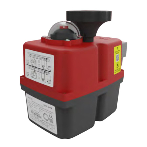
J+J J4C S20 User manual

Quick Start Guide J4C S20-S300
a
ctuatedvalvesupplies.com
Actuated Valves Supplies Ltd
Tel:
+44(0)3300535750
P
roduct
D
escription
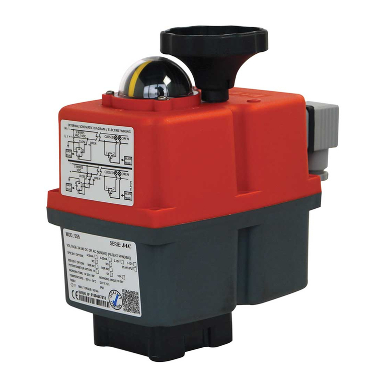
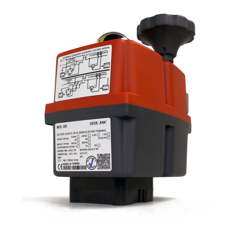
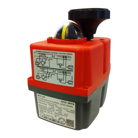
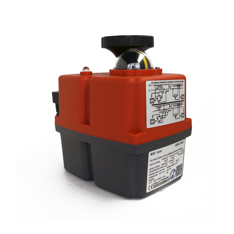
These J+J quarter-turn electromechanical actuators are designed to control and regulate industrial valves.
To maximize versatility, the actuator has a large number of optional modules to argument its operation and an easily configurable
cam system. In the standard version, the drives are pre-adjusted to 0°-90° (0° = closed / 90° = open). Other rotational angles are
also configurable.
The following Quick Start Guide will guide you through all the necessary steps for installation and operation of the actuator.
Please read these carefully before installation.
For special versions, please also refer to the enclosed instructions and the plate.
Function
The actuator automatically detects the operating voltage. Depending on the control signal, it then moves in either a clockwise or
anti-clockwise direction to the predefined end position, which can be set with the cam system and monitored by the limit switches.
The status signals are enabled before the actuator reaches the desired end position using the cam system and two other volt-free
limit switches. During operation, the brushless motor drives the main shaft through the gearbox, the dome position indicator will
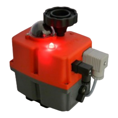
reflect the current position of the valve. Additionally, the operational status is displayed with a multicolored status LED located on
the top of the device.
To prevent condensation buildup in the housing, usually as a result of fluctuations in the external
temperature, the actuator has an automatic, integrated, heater which protects the circuitry (permanent power supply required).
If the valve becomes blocked or jammed, the automatic electronic torque limiter will stop the motor to protect against damage to
the gearbox and motor.
In the event of a power failure or emergency-stop, the manual override can be switched on via the changeover switch and the
driveshaft can then be manually actuated via the handwheel.
Connection
The mechanical connection is made via a standardized mounting according to DIN 3337 / ISO 5211. Each
actuator has a multi-flange plate and is compatible with various shaft mountings. The electrical connection is
made via industrial standard connectors.
Options
Optional moduals are available for a wide variety of functions (refer to product data sheets):
• BSR Battery Failsafe / DPS Digital Positioning System / Potentiometer / different wiring options.
• Golden Contacted Limit Switches for volt-free end position feedback (z.B. SPS) 0,1A 30VDC
Maintenance
Maintenance work is not necessary on J+J rotary electric actuators, however a regular check of the unit’s function is
recommended, especially for rarely used or emergency use actuators.
Important Instructions
All operating instructions must be read carefully and completely before installation.
Where additional models are used, the instructions supplied with the modules should also be read.
Parts of these devices operate under dangerously high voltage. Failure to observe general electrical
safety rules and policies may result in serious personal injury or property damage. Only suitably
qualified personnel should work on or near these devices. All personnel must be familiar with all safety
instructions and maintenance measures in accordance with these operating instructions.
Fault-free and safe operation of these devices require proper transportation, storage, installation /
assembly, as well as careful operation and routine checks.
Notes on the configuration
Before using the actuator, ensure all connections, fittings and surrounding areas are safe, otherwise, long-term damage or
functional failures may occur.
Environment and installation
J+J actuators must not be installed inverted (flange facing upwards). It is important to pay attention to the accessibility of manual override
and visibility of position indicator as well as the status LED when planning your installation.
For applications with vibrations in the pipeline, compensators must be provided.
If the actuator is to be used outdoors, adequate protection (roofing) against adverse weather must be provided.
Strong sunlight can damage the housing due to heat and UV radiation. If the drive is used in
freezing conditions, ice can lead to the manual override becoming unusable.
To avoid condensation, the heater must always be active (permanent electrical connection).
-PAGE 1-

Quick Start Guide J4C S20-S300
a
ctuatedvalvesupplies.com
Actuated Valves Supplies Ltd
Tel:
+44(0)3300535750
Installation
Valve Construction
The torque required to move the valve must never exceed the rated torque of the actuator, taking into account the
medium and the pressure, and after multiplication with a sufficient safety factor.
Before mounting, any caps on the valve must be removed.
If the shaft or flange pattern of the valve cannot be mounted directly with the drive, appropriate adaptations must be
provided. The shaft must never be longer than the insertion depth of the mounting socket.
The assembly can be fixed with grub screws without additional fixings, as long as sufficient screwing depth for the
actuator is possible. In addition, care must be taken during the assembly to align the valve and actuator's operational
positions.
In this regard, it may be helpful to align the actuator by utilizing the manual override (see manual override). Depending on the fitting,
the drive angles may need to be adjusted (see cam system setting instructions).
Electrical connections
Connection of the device may only be carried out by trained and qualified personnel.
All general electrical safety regulations and VDE recommendations should apply.
The connection is made by means of the supplied industrial connectors. When wiring, pay particular attention to using the
correct cable diameter and plug seals, otherwise the IP67 rated protection cannot be guaranteed.
Each DIN plug is fastened to the actuator with a screw, care must be taken to be not be over-tightened.
J+J actuators must be connected in a monophasicly and must be controlled with either relays or switches.
Depending on your requirements, there are three different wiring methods that can be utilized.
An external fuse with appropriate rating and characteristic for motors (for example, MC switch type C) must be provided.
The unit's power must only be connected in parallel with other J+J actuators.
Cable Connectors
A Power Supply Plug
B Optional Plug(s)
C End of Travel Plug
1 Seal
2 Term Block
3 Clamp
4 Housing
5 Seal
6 Clamping Ring
7 Screw Fastener
8 Washer
9 Fixing Screw
10 Seal
Large Plug
Small Plug
Cable Diameter Range 8.0mm -10.5mm 5.0mm – 6.0mm
Type
DIN EN175301-803 Form A DIN EN175301-803 Form C
-PAGE 2-

Quick Start Guide J4C S20-S300
a
ctuatedvalvesupplies.com
Actuated Valves Supplies Ltd
Tel:
+44(0)3300535750
Overview
140
-
300
Version:
20
-
35
-
55
-
85
B
C
D D C
B
A Manual Override Switch
B Handwheel
C Dome indicator
E
D Status LED
A
E Wiring Diagram
F Nameplate
A
F
F
E
Mode
l Comparison
:
Duty
Operating Temp.
Heater Power Ingress (IEC60529)
2x End of Travel Sw.
Rating= 75%
-20°C - +70°C
3.5 W
IP67
SPST NO 5A 125VAC / 3A 250VAC
M
odel
S
pecific
:
Optional 0,1A 30VDC (See Page 1)
Current consumption at max. torque
Runtime
Working
/
Without Load
Modell
24V AC
24V DC
110V AC
230V AC Break Torque
s/90° ±10%
Weight
S 20
1.3A / 30.7W
1.0A / 23.4W
0.3A / 32.7W 0.2A / 46W
20Nm / 25Nm
10s (5.5s)
1.8kg
S 35
1.7A / 40.2W
1.4A / 32.8W
0.4A / 41.9W 0.2A / 46W
35Nm / 38Nm
10s 1.9kg
S 55
2.0A / 47.5W
1.6A / 39.0W
0.4A / 47.0W 0.2A / 46W
55Nm / 60Nm
13s 2.4kg
S 85
1.5A / 36.0W
1.2A / 29.3W
0.3A / 36.5W 0.2A / 46W
85Nm / 90Nm
29s 3.0kg
S140
3.3A / 79.2W
2.5A / 60.7W
0.7A / 78.7W 0.4A / 105.6W
140Nm / 170Nm
25s 5.2kg
S300
3.3A / 79.2W
2.7A / 64.7W
0.8A / 84.7W
0.5A / 113.5W
300Nm / 350Nm
48s 5.2kg
Operation
Status Light
(D)
Operating Status
LED
Flash Sequence
No power supply
Unit is in open position
Unit is in closed position
Unit is in stop position
Unit is moving to open position
Unit is moving to closed position
Torque protection stopped move to open
Torque protection stopped move to closed
Manual Override Engaged
Manual override (A/B)
All J4C models have a manual emergency override for manual operation in the event of a power failure. To activate the
manual override, the "AUTO-MAN" switch (A) must set to "MAN", this declutches the engine from the transmission.
Once in manual you can turn the drive with the handwheel (B).
After about four times the expected actuation time, the engine is automatically stopped by the electronics.
If the drive is to be put back into autonomous operation, switch the switch (A) back to the "AUTO" position and the motor will be
coupled again.
If the motor has switched off automatically, it can be reactivated either by driving in the other direction or by power cycling
the device.
The change-over switch must not be over-tightened.
If the switching is difficult, the gear can be synchronized by means of a handwheel. The screw of the
switch must never be loosened!
-PAGE 3-

Quick Start Guide J4C S20-S300
a
ctuatedvalvesupplies.com
Actuated Valves Supplies Ltd
Tel:
+44(0)3300535750
Cam Adjustment
By adjusting the cams, the swivel angle as well as the end position feedback of the drive can be configured.
The drive is pre-adjusted ex works (see type plate). Depending on the application, or lack of alignment when fitting, it may be necessary
to adjust the actuator's travel.
All work on the open drive must only be carried out under the safety of extra-low voltage or in the de-energized state and
by a suitably qualified specialist.
Failure to follow the general electrical safety procedures may result in serious personal injury or property damage.
1. Opening the case
Required tools: Allen key 3mm (Model 35-300), Torx wrench (T20)
To adjust the cam system, the housing must first be opened. Particular care should be taken to ensure that all gaskets and
screws are carefully stored. The following steps have to be carried out:
• Unscrew and remove all plugs (pay attention to seals)
• Release screw in the handwheel and pull handwheel upwards
• Loosen and remove the housing screws
• Disconnect the housing cover and lay the cover aside (cables can remain connected to the board) and make a note of the
original cable routing.
• Put handwheel back on
2. Adjust the cams
To adjust, the adjustment tool,
which is attached to the engine
bust be removed.
Insert the tool into the respective
cam as shown.
By turning the tool, the cam can
now be adjusted.
Volt-free end position feedback
Cam 1
(Green) Position “open”
Cam 2
(Red) Position “closed”
E
ngine
S
hut
off
Cam 3
(Green) Position “open”
Cam 4
(Red) Position “closed”
Action: The drive must initially be switched from AUTO to MAN.
The cam is moved with the adjusting tool until the click sound of the microswitch is heard. The
cam must always be turned from the direction of the switch, from which the main shaft will
move to this position during operation.
The end position feedback is set so that it switches shortly before reaching the end position
.
The correct setting of the cam positions must always be checked by means of an
electrical test drive (using extra-low voltage for safety). The end positions can then be
measured with a continuity tester on the plug (see wiring diagram)
.
3. closing the case
After completion of the adjustment, the drive can be closed again by reversing the steps described under point 1. Particular
care must be taken to ensure that all screws, seals, individual parts and the internal cabling are returned to their original
positions.
Troubleshooting
The drive moves and then stops. The LED flashes red or green.
»» Operation suspended due to obstruction in operation. Valve and pipeline must be checked!
»» Too weak model selected.
Drive is in position "open" but the valve is closed or half open.
»» Drive has become twisted in relation to the valve. Disassemble drive, move to correct position with handwheel, remount.
The limit switches for end position feedback do not work.
»» Check the wiring. Check the adjustment of the cams so that they trigger shortly before reaching the end position.
The drive moves, the valve does not move.
»» The adaptor between actuator and valve is damaged or incorrectly dimensioned.
-PAGE 4-
Setting tool
Other manuals for J4C S20
2
This manual suits for next models
5
Other J+J Controllers manuals
Popular Controllers manuals by other brands

Victron energy
Victron energy MultiPlus-II 48/3000/35-32 230V GX manual

PIETRO FIORENTINI
PIETRO FIORENTINI APERFLUX 851 Installation, commissioning and maintenance instructions

FujiFilm
FujiFilm PXG4 Operation manuals

TIS
TIS ES-10F-CM Manual Installation

dIXEL
dIXEL IPC400D SERIES user manual

Severn Trent
Severn Trent NXT3000 Series Instruction bulletin