manuals.online logo
Brands
  1. Home
  2. •
  3. Brands
  4. •
  5. J+J
  6. •
  7. Controllers
  8. •
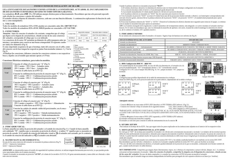
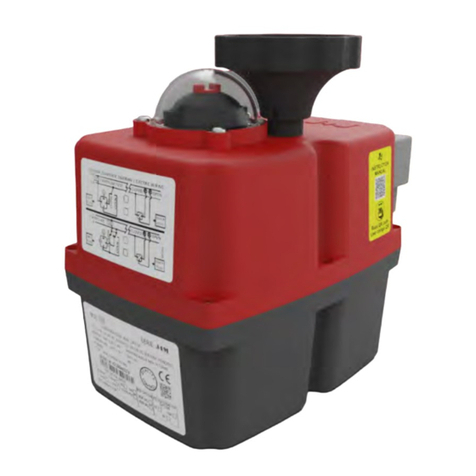
  9. J+J J4C S 20 User manual

J+J J4C S 20 User manual

J+J
subject to technical changes
Manual J4C S20-S300
-PAGE 1-
Product description
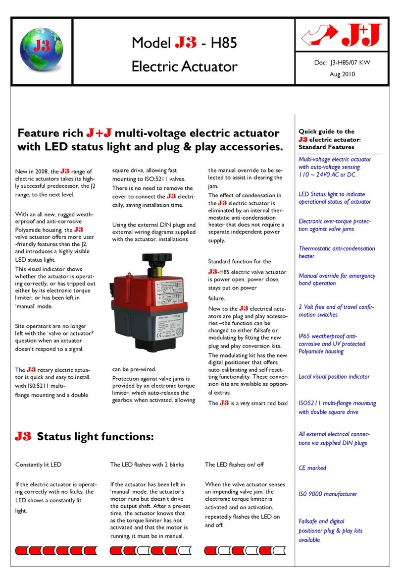
The electromechanical J+J quarter-turn actuators are designed to control and regulate industrial valves. For this purpose, the
drive has a large number of supporting systems and a freely congurable cam system. In the standard version, the drives are
pre-adjusted to 0°-90° (0° = closed / 90° = open). Other working angles are also available. The following manual will guide you
through all the necessary steps for installation and operation of the actuator.
Read this manual carefully before installation and commissioning in order to avoid mistakes!
For special models, the enclosed additional instructions and the type label / wiring diagram of the device apply additionally.
Function
The drive automatically detects the connected operating voltage. Depending on the control, it moves in clockwise or
counter-clockwise direction into its predened end position, which is set via the cam system and interrogated by limit switches.
The signaling is done before reaching the end position also via the cam system and two other limit switches, which are
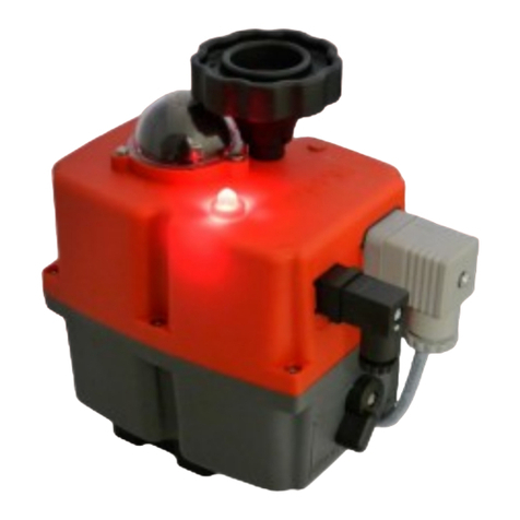
potential-free interrogated. While the brushless motor drives the main shaft via the gearbox, the DOME position indicator
permanently shows the position of the valve. In addition, the operating status is displayed via the multicolored status LED.
To prevent condensation in the housing when the outside temperature uctuates, the actuator has an automatic heater, which
protects the interior. For this, the actuator needs a permanent power supply.
If the valve is blocked or has a high torque, the electronic torque limiter protects against damage to gear and motor.
In the event of a power failure or emergency intervention, the manual override can be switched on via the changeover switch
and the actuator can then be manually turned via the handwheel.
Connections
The mechanical connection is made via a standardized interface according to DIN 3337 / ISO 5211.
For this purpose, each drive has a multi-ange plate and is available with various shaft outputs.
The electrical connection is made via industrial connectors (see connection plug).
Options
Optional functions are available for a wide range of applications (for more information see data sheets):
• BSR Battery safety return / DPS Digital positioning system / Potentiometer / different wiring options
• Gold platet end switches für lastlose Abfrage der Endlagenrückmeldung (z.B. SPS) 0,1A 30VDC
Maintenance
Maintenance work is not necessary on J+J actuators. A regular check of the function is recommended according to the safety
requirements of the system, especially for rarely used actuators.
Important instructions
The operating instructions must be read carefully and completely before installation.
For special models, the additional instructions are always valid.
The faultless and safe operation of the devices requires proper transport, professional storage,
installation and assembly as well as careful operation and maintenance.
When operating electrical devices, certain parts of these devices are inevitably under dangerous voltage.
Not noticing the general electrical safety regulations may result in serious personal injury or property
damage. Only qualied personnel may work on or near these devices. The staff must be familiar with all
safety instructions and maintenance according with this operating instruction.
Notes for planning
Before using the electric actuator, all circumstances relating to the connection, tting and surrounding area must be claried.
Otherwise long-term damage or a functional failure may occur.
Environment and installation position
Do not install J+J actuators overhead (ange upwards).
It is always important to pay attention to the accessibility of the manual override and visibility of position indicator and status LED.
In applications with vibrations in the pipeline, line compensators shall be installed.
If actuators are used outdoor, adequate protection (roong) against climatic inuences must be provided. Strong sunlight can
damage the drive due to heat development and UV radiation. Icing of the drive can lead to the unusability of the manual override.
To avoid condensation, the internal heater must always be active (see electrical connection).
Geändert: 12.12.2018
Name: MU
J+J®Deutschland GmbH Brunnenweg 7
31061 Alfeld Tel.: +49 5181 85590-0
Fax.: +49 5181 85590-29 [email protected]
www.juj-deutschland.de
big plug small plug
Max. cable diameter 8mm -10,5mm 5mm - 6mm
Type DIN EN175301-803 Form A Industrial connector type C
AC/DC
Steuerung 2 Punkt control 2 point
Anschluss connection
DC
Interne Funktion internal function
Versorgungsstecker
supply plug
Endlagenstecker
end position plug
Regelung 3 Punkt regulation 3 point
Steuerung 2 Draht control 2 wires
J+J Manual J4C S20-S300
-PAGE 2-
Commissioning
Mounting on the valve
Taking the medium and pressure into account, as well as after multiplication with a sufcient safety factor, the torque of the valve
may never exceed the rated torque of the drive. Before mounting, any end stops of the valve must be removed.
If the shaft or ange pattern of the valve can not be directly mounted with the drive, corresponding adaptions are needed.
The shaft of the valve may never be longer than the insertion depth of the actuators output.
The assembly can be done with grub screws, ensuring a sufcient screwing depth in the drive.
In addition, care must be taken during assembly to align the valve and actuator.
In this case, it can be helpful to bring the alignment by using the manual override (see manual override).
Depending on the valve, the working angle may need to be adjusted (see adjustment of cam system).
Electric connection
The connection may only be made by electrically trained specialist personnel.
The general electrical safety rules and VDE regulations apply.
The connection is made with the supplied industrial connectors. While wiring always take care of a correct cable diameter,
otherwise the degree of protection IP67 is not guaranteed.
Each plug is fastened to the quarter-turn actuator with a screw, it must not be over-tightened.
J+J quarter-turn actuators must be connected with a single phase and controlled via relays or switches.
Depending on requirements, three different wiring methods without reconguration are available for the control.
Due to the internal power supply, the actuator can be viewed as a capacitive load.
Accordingly, an external fuse with appropriate trigger characteristics (e.g. circuit breaker type D) must be provided.
Switching contacts should have a suitable contact material (e.g. silver-tin oxide AgSnO) or a zero voltage switch.
No external consumers should be connected parallel to the actuator.
AC/DC
Steuerung 2 Punkt control 2 point
Anschluss connection
DC
Interne Funktion internal function
Versorgungsstecker
supply plug
Endlagenstecker
end position plug
Regelung 3 Punkt regulation 3 point
Steuerung 2 Draht control 2 wires
9
8
10
4
1
23
5
6
7
1 Sealing
2 Terminal block
3 Clamp
4 Housing
5 Sealing ring
6 Clamp ring
7 screw-in pod
8 Washer
9 Screw
10 Sealing washer
Connection plugs
A Supply plug
B Option
C End position plug
ABC
1
23
4
5
6
7
9
8
10
J+J
Manual J4C S20-S300
-PAGE 3-
Overview
Operation
Status LED (D)
Manual override (A/B)
All J4C models have a manual emergency transmission for manual operation in case of a power failure. For manual override turn
the switch „AUTO-MAN“ (A) to „MAN“. This decouples the motor from the gear.
Now you can turn the actuator with the handwheel (B).
After about four times of the working time, the motor is automatically stopped by the electronics.
To put the actuator back in automatic mode after manual actuation, turn the switch „AUTO-MAN“ (A) to the „AUTO“ position.
Now the motor is coupled again. If the motor has switched off automatically, this can be reversed either by driving to the other
direction or by reactivating with a short power interruption (removal of the power plug).
The switch „AUTO-MAN“ must not be turned over its predetermined switch positions.
If the switching is difcult, the gear can be synchronized by using the handwheel.
The screw of the switch must never be loosened!
All models:
Model specic:
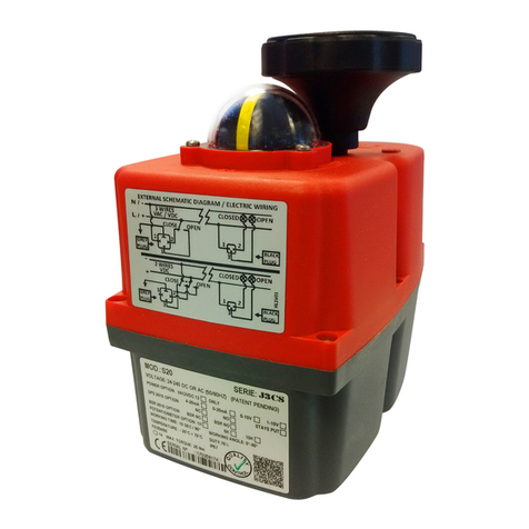
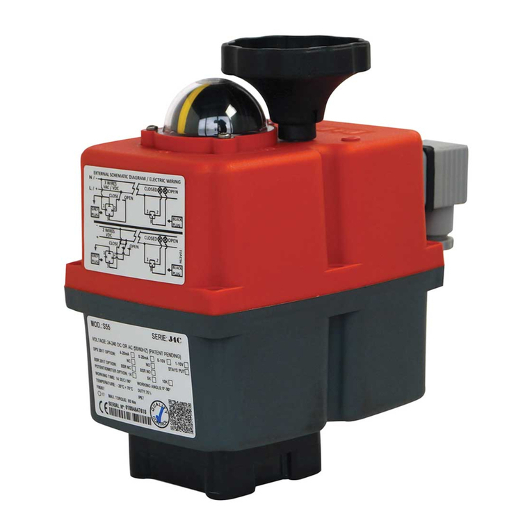
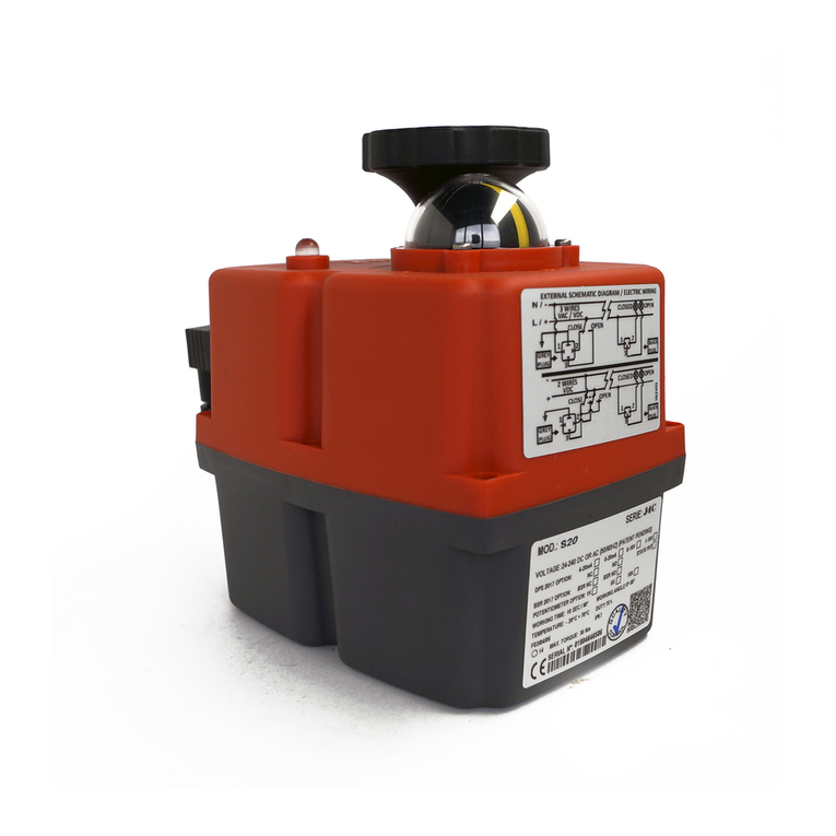
A Switch manual override
B Handwheel
C DOME position indicator
D Status LED
E Wiring diagram
F Type label
20-35-55-85 140-300
Description
Model
Current consumption with max. torque
Voltage range: 24-240V AC (50/60Hz) / 24-135 DC Work- /
Break torque
Working time
without load
s/90° ±10% Weight24V AC 24V DC 110V AC 230V AC
S 20 1,3A / 30,7W 1,0A / 23,4W 0,3A / 32,7W 0,2A / 46W 20Nm / 25Nm 10s (5,5s) 1,8kg
S 35 1,7A / 40,2W 1,4A / 32,8W 0,4A / 41,9W 0,2A / 46W 35Nm / 38Nm 10s 1,9kg
S 55 2,0A / 47,5W 1,6A / 39,0W 0,4A / 47,0W 0,2A / 46W 55Nm / 60Nm 13s 2,4kg
S 85 1,5A / 36,0W 1,2A / 29,3W 0,3A / 36,5W 0,2A / 46W 85Nm / 90Nm 29s 3,0kg
S140 3,3A / 79,2W 2,5A / 60,7W 0,7A / 78,7W 0,4A / 105,6W 140Nm / 170Nm 25s 5,2kg
S300 3,3A / 79,2W 2,7A / 64,7W 0,8A / 84,7W 0,5A / 113,5W 300Nm / 350Nm 48s 5,2kg
Duty cycle Temperature range Heater Protection IEC60529 2x End position switches
ED= 75% -20°C - +70°C 3,5 W IP67 SPST NO 5A 125VAC / 3A 250VAC
Operation status LED
Without power supply
Actuator is in opened position
Actuator is in closed position
Actuator is in stop position
Actuator is turning in open direction
Actuator is turning in close direction
Torque limiter active in open direction
Torque limiter active in close direction
Manual override active, motor was stopped
A
A
BB
D
E
F
EF
C CD
Optional 0,1A 30VDC (see page 1)
J+J
subject to technical changes
Manual J4C S20-S300
-PAGE 4-
J+J®Deutschland GmbH Brunnenweg 7
31061 Alfeld Tel.: +49 5181 85590-0
Fax.: +49 5181 85590-29 [email protected]
www.juj-deutschland.de
Adjustment of the cam system
With the cam system, the working angle as well as the end position feedback of the actuator can be adjusted.
The drive is pre-adjusted ex works (see type label). Depending on application, valve, lack of alignment or adapters, it may be
necessary that the drive has to be adjusted in its travel.
All work on the opened actuator must be under protective extra-low voltage or without any voltage applied
and carried out by appropriately qualied personnel. Not complying with the general Electro safety rules can
result in serious injury or property damage.
Volt free end position feedback
Cam 1 (green) Position „open“
Cam 2 (red) Position „close“
Motor shutdown
Cam 3 (green) Position „open“
Cam 4 (red) Position „close“
1. Open the housing
Needed tools: Allen Key 3mm (Models 35-300), Torx key T20
To adjust the cam system, the housing must rst be opened. Particular care should be taken to ensure that all sealings and
screws are carefully stored. The following steps have to be carried out:
• Unscrew all plugs (watch the plugs sealing)
• Loosen screw in handwheel and pull handwheel upwards
• Loosen and remove the housing screws
• Remove the cover (observe the circumferential housing seal, as well as the shaft seal and snap ring of the handwheel)
• Lay the cover aside (cables can remain connected to the board) and pay attention to the original cable routing
• Put handwheel back on (to turn it while adjusting the cams)
2. Adjusting the cams
For adjustment, rst the adjusting
tool is needed, which is attached
to the motor. To adjust a cam, the
tool needs to be plugged in it, as
shown in the picture „plugged in
tool“. By turning the tool, the cam
can now be adjusted.
Plugged in tool
3. Close the housing
After completing the adjustment, the actuator can be closed again by reversing the steps described under point 1 in reverse order.
Particular care must be taken to ensure that all screws, seals, individual parts and the internal cable routing are returned to their
original position.
Proceeding: The Actuator is rst switched from AUTO to MAN.
The position to be set is then approached by handwheel.
Now the adjusting tool is plugged in the respective cam and is twisted until the click
sound of the microswitch is heard. The cam must always be turned to the switch from
the direction which the main shaft will move in electrical operation to this position.
The end position feedback is set to switch shortly before reaching the end position.
The correct setting of the cam positions must always be checked with an electrical
test drive (use safety extra-low voltage). The end positions can be measured with a
continuity tester on the plug (see wiring diagram).
Troubleshooting
The actuator moves and then stops. The operating LED ashes red or green (see status LED).
»High torque on the valve due to not removed end stops or solids in the valve. Valve must be checked!
»Model size of the actuator is too small.
The actuator is in position „open“ but the valve is closed or half opened.
»Actuator is mounted on the valve with a wrong angle. Dismount, turn the actuator in manual mode to correct angle, mount it.
The limit switches for end position feedback do not work.
»Check the wiring. Check the adjustment of the cams so that they trigger shortly before reaching the end position.
»In load-free interrogation of the limit switch, soot is formed inside. Actuator with gold contact switches are to be used.
The actuator moves, but the valve does not.
»The connection between actuator and valve is damaged or incorrectly dimensioned.
For other malfunctions, please contact our technical service department.
Geändert: 12.12.2018
Name: MU
Angle
Powered by TCPDF (www.tcpdf.org)Powered by TCPDF (www.tcpdf.org)

This manual suits for next models

8

Other J+J Controllers manuals

J+J J2-LI40 Guide

J+J

J+J J2-LI40 Guide

J+J J4C Series User manual

J+J

J+J J4C Series User manual

J+J S2 User manual

J+J

J+J S2 User manual

J+J J3-35 User manual

J+J

J+J J3-35 User manual

J+J J4C S20 User manual

J+J

J+J J4C S20 User manual

J+J J4M Series User manual

J+J

J+J J4M Series User manual

J+J J4C 20 User manual

J+J

J+J J4C 20 User manual

J+J J4C Series User manual

J+J

J+J J4C Series User manual

J+J J4C S20 User manual

J+J

J+J J4C S20 User manual

J+J J3C User manual

J+J

J+J J3C User manual

J+J J3C S20 User manual

J+J

J+J J3C S20 User manual

J+J J4S 09 Series User manual

J+J

J+J J4S 09 Series User manual

J+J J2 L/H 10 User manual

J+J

J+J J2 L/H 10 User manual

J+J S 20 User manual

J+J

J+J S 20 User manual

J+J J4C S20 User manual

J+J

J+J J4C S20 User manual

Popular Controllers manuals by other brands

SmartLine SL800 owner's manual

SmartLine

SmartLine SL800 owner's manual

Sevcon MillipaK manual

Sevcon

Sevcon MillipaK manual

Agilebot IRC-I8A-S product manual

Agilebot

Agilebot IRC-I8A-S product manual

Emerson EXD-SH1 operating instructions

Emerson

Emerson EXD-SH1 operating instructions

Pilz PSS Series operating manual

Pilz

Pilz PSS Series operating manual

Euroterm 2604 Installation and wiring instructions

Euroterm

Euroterm 2604 Installation and wiring instructions

Digikeijs DR5052 DIGITURN instruction manual

Digikeijs

Digikeijs DR5052 DIGITURN instruction manual

YASKAWA A1000 Series Technical manual

YASKAWA

YASKAWA A1000 Series Technical manual

Watts ARA VT+ Installation and operation manual

Watts

Watts ARA VT+ Installation and operation manual

CASTLE WFS-25-S operating instructions

CASTLE

CASTLE WFS-25-S operating instructions

Webasto UniControl installation instructions

Webasto

Webasto UniControl installation instructions

Siemens RAJA+ Installation, operation & maintenance instructions

Siemens

Siemens RAJA+ Installation, operation & maintenance instructions

Motorola MaraTrac Advanced Control Head operating instructions

Motorola

Motorola MaraTrac Advanced Control Head operating instructions

Milwaukee MC720 user manual

Milwaukee

Milwaukee MC720 user manual

Smartgen HSC960 user manual

Smartgen

Smartgen HSC960 user manual

resideo Braukmann FR124 installation instructions

resideo

resideo Braukmann FR124 installation instructions

Renkus-Heinz X24 owner's manual

Renkus-Heinz

Renkus-Heinz X24 owner's manual

Redback A 4565B operating manual

Redback

Redback A 4565B operating manual

manuals.online logo
manuals.online logoBrands
  • About & Mission
  • Contact us
  • Privacy Policy
  • Terms and Conditions

Copyright 2025 Manuals.Online. All Rights Reserved.