manuals.online logo
Brands
  1. Home
  2. •
  3. Brands
  4. •
  5. J+J
  6. •
  7. Controllers
  8. •
  9. J+J J4C 20 User manual

J+J J4C 20 User manual

ASSEMBLY INSTRUCTIONS J4C 20/85
MOUNTING INSTRUCTIONS J4C 20/85
PIECES
A - 1 Cover
B - 1 Plasc column
C - 1 DPS posioner PCB
D - 2 Sheet metal Fixing screws
E - 1 Plasc Fixing screws
PREPARING THE COVER:
The cover of the kit is for a J4C-20, 35 and 55 models. In case you want to mount a kit on a J4C85,
follow the instrucons:
A
C
D
E
B
Remove the
cap and leave
the o-ring
inside the hole
Remove the
sleeve 1 and
leave the
Oring inside.
Introduce the
sleeve in hole
A and press it
unl is fully
inside(Fig.A)
Introd uce the
cap in hole B
and press it
unl it is fully
inside (Fig.B)
sleeve
O-ring
sleeve
1
AB
cap
O-ring
cap
PLEASE READ CAREFULLY BEFORE MOUNTING.
VERY IMPORTANT!!!! PLEASE FOLLOW THE INSTRUCTIONS STEP BY STEP. BEFORE CON-
NECTING “A” PLUG TO THE ACTUATOR,
CHECK THAT THE VOLTAGE IS THE SAME AS THE ONE SPECIFIED ON THE LABEL (CARTER).
TO CONVERT A STANDARD (ON-OFF) J4C ELECTRIC ACTUATOR INTO A MODULATING
FUNCTION WITH POSITIONER, PROCEED AS FOLLOWS:
ASSEMBLY INSTRUCTIONS J4C 20/85
MOUNTING INSTRUCTIONS J4C 20/85
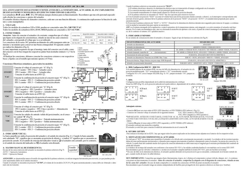
The unit must be disconnected from any electrical power or signal before installing.
1. Remove the screw, which is fixing the hand wheel. (Fig. 2)
2. Remove the 6 screws, which are fixing the body to the cover of the actuator (Fig.3).
3. Carefully li the cover (Fig.4).
4. Remove the cables (from the cover) connected to the actuator PCB (Fig.5A,5B and 5C).
5. Carefully remove the posion indicator (Fig.6).
6. Fix the plasc column (B) on the base plate, by using 2 sheet metal fixing screws (D)(Fig.7A,7B and 7C).
7. Take the DPS cover (A) and connect its cables, following (Fig.8A,8B and 8C).
8. Place the menoned cables as per (Fig.9A and 9B).
9. Mount the DPS posioner PCB (C), matching the cle of the sha with the key inside the DPS gear (Fig.10).
10. Press the DPS posioner PCB (C) along the sha unl the PCB connector (JP3) is plugged in the actuator
PCB connector (JP2) (Fig.11).
11. Fix the DPS posioner PCB (C) to the plasc column (B) with the plasc fixing screw (E) (Fig.12A).
12. Connect the remaining cable (A) to the connector base on the DPS PCB (C) (Fig. 12B).
13. Carefully insert the posion indicator, matching its inner key with the cle of the sha (Fig.13).
14. In order to set the actuator up, use the DIPs shown in picture (Fig.14). Put DIP 1 in ON posion, connect
the grey connector to the power supply, put DIP 1 back to the prior posion. Wait unl the actuator make
a complete maneuver (Fig. 14A and 14B).
15. Disconnect the grey connector from the power supply.
16. Use the configuraon you need by moving the DIPs, according to the instrumentaon signal (Fig. 15)
17. Care- fully mount the cover, minding the cables not to be pressed (Fig.16).
18. Fix the cover to the body by using the 6 screws (Fig.17).
19. Mount the hand wheel on the sha and fix it by using the screw (Fig.18).
20. Mount the 3 outer connectors together with its rubber joints and fix them to the cover, by using the
screws (Fig.19).
21. Fill in the document inside the kit, and send it to the fax number or e-mail, shown in the document
The unit is ready to work.
Outer Set-Up: Only if necessary.
- B plug - Connect a cable between PIN 1 and PIN Earth (Fig. 20).
- A plug - Connect it to the power supply.
- B plug, disconnect the cable between PIN 1 and PIN Earth.
The actuator will make a complete maneuver.
Connect B connector to the actuator. The actuator is ready to work.
ASSEMBLY INSTRUCTIONS J4C 20/85
MOUNTING INSTRUCTIONS J4C 20/85
ASSEMBLY INSTRUCTIONS J4C 140/300
MOUNTING INSTRUCTIONS J4C 140/300
PIECES
A - 1 Cover
B - 1 Plasc column
C - 1 DPS posioner PCB
D - 2 Sheet metal Fixing screws
E - 1 Plasc Fixing screws
F - 1 Schemac iagram lael
A
C
D
E
F
B
PLEASE READ CAREFULLY BEFORE MOUNTING.
VERY IMPORTANT!!!! PLEASE FOLLOW THE INSTRUCTIONS STEP BY STEP. BEFORE CON-
NECTING “A” PLUG TO THE ACTUATOR, CHECK THAT THE VOLTAGE IS THE SAME AS THE
ONE SPECIFIED ON THE LABEL (CARTER).
TO CONVERT A STANDARD (ON-OFF) J4C ELECTRIC ACTUATOR INTO A MODULATING
FUNCTION WITH POSITIONER, PROCEED AS FOLLOWS:
The unit must be disconnected from any electrical power or signal before installing.
1. Remove the screw, which is fixing the hand wheel. (Fig.2A and 2B)
2. Remove the 8 screws, which are fixing the body to the cover of the actuator (Fig.3).
3. Carefully li the cover (Fig.4).
4. Remove the cables (from the cover) connected to the actuator PCB (Fig.5A, 5B & 5C).
5. Carefully remove the posion indicator (Fig.6).
6. Fix the plasc column (B) on the base plate, by using 2 sheet metal fixing screws (D) (Fig.7A,7B & 7C).
7. Take the DPS cover (A) and connect its cables, following (Fig.8A, 8B & 8C).
8. Mount the DPS posioner PCB inside the kit (C), matching the cle of the sha with the key inside the DPS
gear (Fig.9).
9. Press the DPS posioner PCB (C) along the sha unl the PCB connector (JP3) is plugged in the actuator PCB
connector (JP2) (Fig.10).
10. Fix the DPS posioner PCB (C) to the plasc column (B) with the plasc fixing screw (E) (Fig.11A).
11. Connect the remaining cable from the kit cover (A) to the connector base on the DPS PCB (C) (Fig.11B).
12. Carefully insert the posion indicator, matching its inner key with the cle of the sha (Fig.12).
13. In order to set the actuator up, use the DIPs shown in picture (Fig.13).
Put DIP 1 in ON posion, connect the grey connector to the power supply, put DIP 1 back to the prior
posion. Wait unl the actuator make a complete maneuver (Fig.13A and 13B).
ASSEMBLY INSTRUCTIONS J4C 140/300
MOUNTING INSTRUCTIONS J4C 140/300
14. Disconnect the grey connector from the power supply.
15. Use the configuraon you need by moving the DIPs, according to the instrumentaon signal (Fig.14):
16. Care- fully mount the cover, minding the cables not to be pressed (Fig.15).
17. Fix the cover to the body by using the 8 screws (Fig.16).
18. Mount the hand wheel on the sha and fix it by using the screw (Fig.17).
19. Mount the 3 outer connectors together with its rubber joints and fix them to the cover, by using the
screws (Fig.18).
20. Remove the wiring label from the actuator and replace it by the one inside the kit box (F).
21. Fill in the document inside the kit, and send it to the fax number or e-mail, shown in the document.
The actuator is ready to work.
Outer Set-Up: Only if necessary.
- B plug - Connect a cable between PIN 1 and PIN Earth (Fig.19).
- A plug - Connect it to the power supply.
- B plug, disconnect the cable between PIN 1 and PIN Earth.
The actuator will make a complete maneuver.
Connect and fix the B outer connector to the actuator. The actuator is ready to work.
ASSEMBLY INSTRUCTIONS J4C 140/300
MOUNTING INSTRUCTIONS J4C 140/300

This manual suits for next models

5

Other J+J Controllers manuals

J+J J4C S20 User manual

J+J

J+J J4C S20 User manual

J+J J4M Series User manual

J+J

J+J J4M Series User manual

J+J J3C User manual

J+J

J+J J3C User manual

J+J J4C S 20 User manual

J+J

J+J J4C S 20 User manual

J+J J4C Series User manual

J+J

J+J J4C Series User manual

J+J J2-LI40 Guide

J+J

J+J J2-LI40 Guide

J+J J4S 09 Series User manual

J+J

J+J J4S 09 Series User manual

J+J J3-35 User manual

J+J

J+J J3-35 User manual

J+J S2 User manual

J+J

J+J S2 User manual

J+J J4C S20 User manual

J+J

J+J J4C S20 User manual

J+J S 20 User manual

J+J

J+J S 20 User manual

J+J J2 L/H 10 User manual

J+J

J+J J2 L/H 10 User manual

J+J J3C S20 User manual

J+J

J+J J3C S20 User manual

J+J J4C S20 User manual

J+J

J+J J4C S20 User manual

J+J J4C Series User manual

J+J

J+J J4C Series User manual

Popular Controllers manuals by other brands

SmartLine SL800 owner's manual

SmartLine

SmartLine SL800 owner's manual

Sevcon MillipaK manual

Sevcon

Sevcon MillipaK manual

Agilebot IRC-I8A-S product manual

Agilebot

Agilebot IRC-I8A-S product manual

Emerson EXD-SH1 operating instructions

Emerson

Emerson EXD-SH1 operating instructions

Pilz PSS Series operating manual

Pilz

Pilz PSS Series operating manual

Euroterm 2604 Installation and wiring instructions

Euroterm

Euroterm 2604 Installation and wiring instructions

Digikeijs DR5052 DIGITURN instruction manual

Digikeijs

Digikeijs DR5052 DIGITURN instruction manual

YASKAWA A1000 Series Technical manual

YASKAWA

YASKAWA A1000 Series Technical manual

Watts ARA VT+ Installation and operation manual

Watts

Watts ARA VT+ Installation and operation manual

CASTLE WFS-25-S operating instructions

CASTLE

CASTLE WFS-25-S operating instructions

Webasto UniControl installation instructions

Webasto

Webasto UniControl installation instructions

Siemens RAJA+ Installation, operation & maintenance instructions

Siemens

Siemens RAJA+ Installation, operation & maintenance instructions

Motorola MaraTrac Advanced Control Head operating instructions

Motorola

Motorola MaraTrac Advanced Control Head operating instructions

Milwaukee MC720 user manual

Milwaukee

Milwaukee MC720 user manual

Smartgen HSC960 user manual

Smartgen

Smartgen HSC960 user manual

resideo Braukmann FR124 installation instructions

resideo

resideo Braukmann FR124 installation instructions

Renkus-Heinz X24 owner's manual

Renkus-Heinz

Renkus-Heinz X24 owner's manual

Redback A 4565B operating manual

Redback

Redback A 4565B operating manual

manuals.online logo
manuals.online logoBrands
  • About & Mission
  • Contact us
  • Privacy Policy
  • Terms and Conditions

Copyright 2025 Manuals.Online. All Rights Reserved.