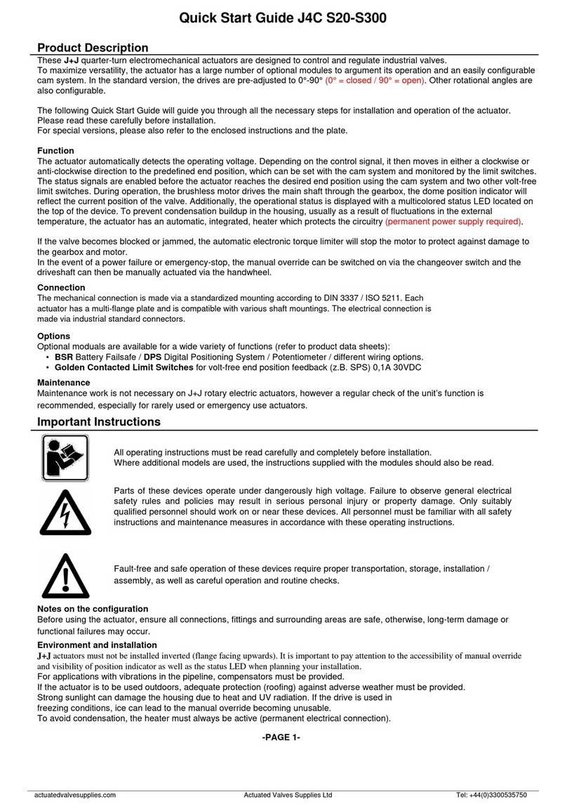
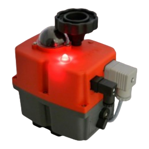
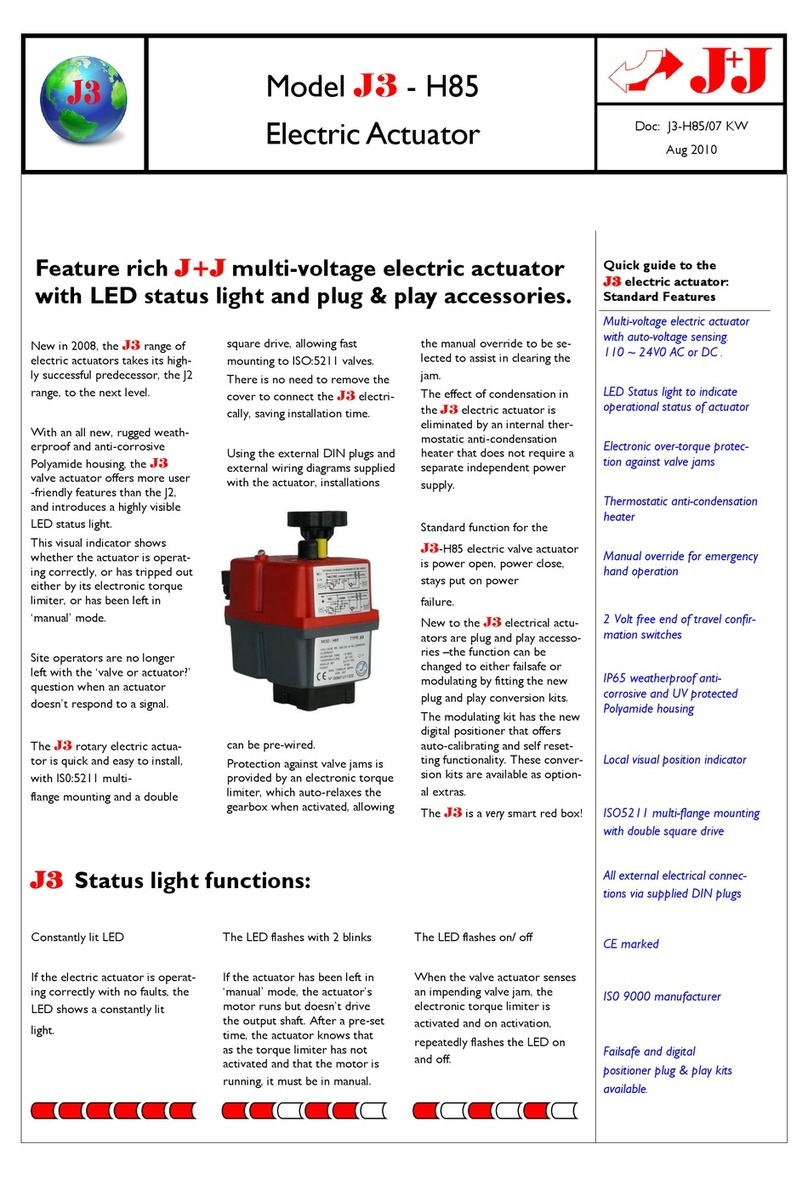
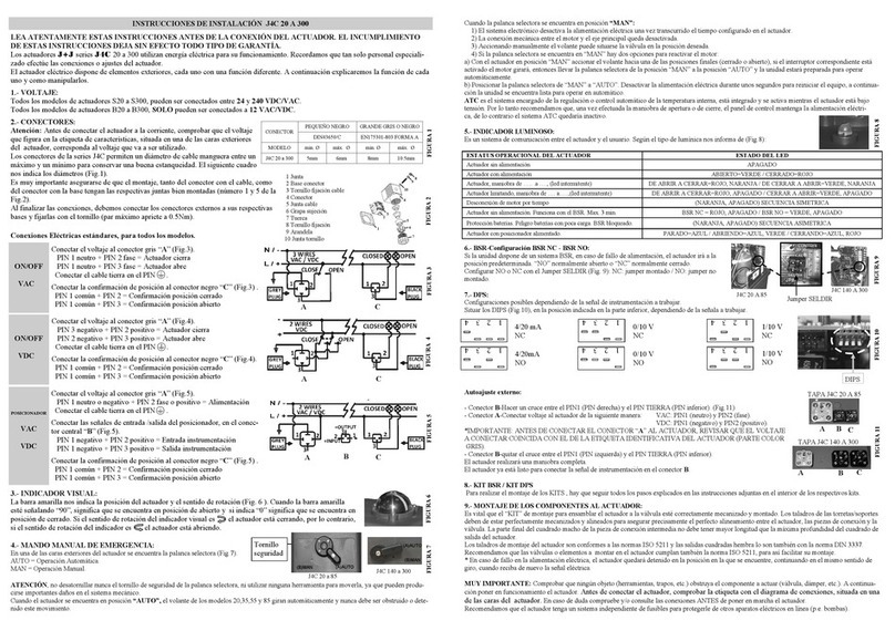
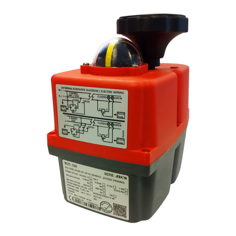
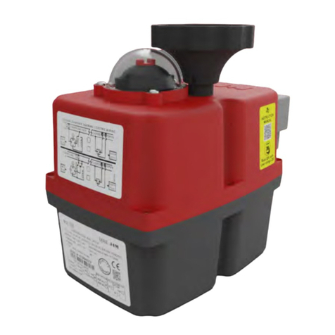
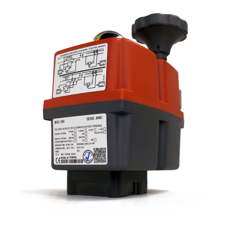
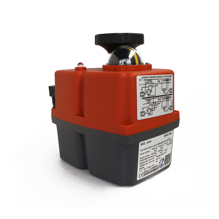
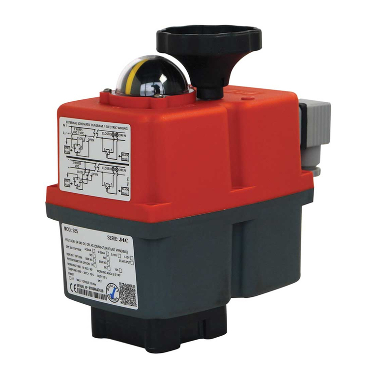
J+J S 20 User manual

www.jjbcn.com
HANDBOOK
J.J. BCN INTERNACIONAL, S.A.
Handbook (EN) 22-07 V3

INDEX
01. Actuator Part List
·S20, S35, S55, S85, B20, B35, B55, B85
·S140, S300, B140
02. J4C Series
· Voltage
· Electrical Connectors
· ID Actuator Label
· Local Visual Posion Indicator
· Emergency Manual Override Facility
· Adjustment of the Cams
· Table of Consumpons
· External Connecng Diagram
· Actuator Operaonal Status
03. Datasheet
· J4C 20
· J4C 35
· J4C 55
· J4C 85
· J4C 140
· J4C 300
04. Opons
· DPS
· BSR
· Bluetooth
· Modbus
05. Kits
· DPS
· BSR
· INTERFACE
06. Cerficaons
07. Guarantee
08. Contact
HANDBOOK

02 J4C SERIES
HANDBOOK_J4C SERIES 05
J4C Electric actuators operate with the use of live electricity. It is recommended that only qualified
electrical engineers be allowed to connect or adjust these actuators.
READ THESE INSTRUCTIONS BEFORE CONNECTING THE ACTUATOR. DAMAGE CAUSED BY
NON COMPLIANCE OF THESE INSTRUCTIONS IS NOT COVERED BY OUR WARRANTY.
Warning: Ensure that the square rubber seal is in place when fixing each
DIN plug to the actuator. Failure to do so could allow water ingress and
damage caused by this installaon error will invalidate any warranty. The
DIN plugs are fixed to their respecve bases on the actuator housing with
a screw. Do not over ght the screw (8) when assembling (Max. 0.5Nm ).
1. Gasket
2. Terminal strip
3. Cable fixing screws
4. Housing
5. Washer
6. Grommet
7. Gland - nut
8. Fixing screw
9. Washer
10. Gasket
All our actuators model S20 to S300 are ready to work from 24-240 VDC/VAC.
All our actuators model B20 to B300 are ready to work at 12 VDC/VAC ONLY.
VOLTAGE TO BE CONNECTED
Warning: Before connecng ensure that the voltage to be applied to the actuator is within the range
shown on the idenficaon label. The supplied electrical connectors, used to connect to the actuator
are DIN plugs. Ensure the diameter of cable to be used conforms to the maximum and minimum
requirements of the DIN plugs to maintain water ghtness (Fig.1).
ELECTRICAL CONNECTORS
INDEX

_04
HANDBOOK_J4C SERIES 06
INDEX
ID ACTUATOR LABEL
1 - Actuator Model.
2 - Voltage to be connected.
3 - Time the actuator needs to run to the
indicated degrees.
4 - Actuator ready to bear between –20ºC
& + 70ºC.
5 - Plate to fix the valve to the actuator,
following ISO 5211.
6 - Female output drive size, following DIN3337.
7 - Maximum torque break.
8 - Actuator serial number.
9 - Bar code of the serial number.
10 - Actuator Series.
11 - Working angle.
12 - Duty: 75%. Example: S20 Model -
Maneuver me = 10sec.
Time between maneuvers = 3.3 sec.
13 - Actuator with the IP67 protecon.
14 - Actuator with the CE cerficate.
15 - Quality Control Conformity .
16 - QR code for manufacturing.
17 - DPS opons.
18 - BSR opons.
19 - POTENTIOMETER opons.
110
11
12
14
13
15
16
19
18
2
3
4
5
6
8
9
17
24-240 AC (50/60HZ) / 24-135 DC (PATENT PENDING)
OUT different of IN:
Nm

HANDBOOK_J4C SERIES 07
INDEX
LOCAL VISUAL POSITION INDICATOR
All J4C actuators are supplied with a local visual posion indicator comprises a black base with a
yellow insert that shows, both the posion and direcon of rotaon (Fig.6).
The open and close posions have the following logos molded into the top cover OPEN 90 and CLOSE
0. Opening = Closing =
Fig. 6 0 = CLOSE Fig. 6 90 = OPEN
TWO YELLOW INDICATORS:
For 3 way ball valve, L port.
THREE YELLOW INDICATORS:
For 3 way ball valve, T port.

HANDBOOK_J4C SERIES 08
INDEX
The J4C has 2 operang modes, automac and manual, the required mode is selected by using a
lever on the lower half of the actuator housing (Fig 7).
The 2 posions are marked:
AUTO = Automac operaon
MAN = Manual operaon
Warning: Do not remove the selector lever securing screw, as this will allow its internal mechanism
to become loose and will cause irreparable damage to the actuator’s gearbox.
Removing this screw will invalidate the warranty.
When “AUTO” posion is selected:
The hand wheel, of models 20,35,55, and 85 rotates automacally, it is very important not to block
it, otherwise the actuator could suffer unrepairable damages.
EMERGENCY MANUAL OVERRIDE FACILITY:
Fig. 7 J4C 20 TO 85 Fig. 7 J4C 140 TO 300
J4C 20 TO 85
Hand Wheel
J4C 140 TO 300
Posion Indicator
Automac - Manual

HANDBOOK_J4C SERIES 09
INDEX
When “MAN” funcon is selected:
1 - The electronic system cuts the power to the motor aer a few minutes.
2 - The mechanical connecon between the motor and the output sha is disconnected.
3 - The desired posion can be achieved by using the hand wheel.
4 - There are two ways to re-acve the motor aer being isolated whilst in “MAN” posion:
a) With the actuator in “MAN” funcon, turn the hand wheel to one of the end posions (open
or close). If the end posion switch is acvated the motor stops. Now change the manual
override from “MAN” to “AUTO” , and the actuator is ready to operate automacally again.
b) Change from “MAN” mode to “AUTO”. Deacvate the supply voltage for a few seconds
which resets the actuator and it could operate automacally again.
Under normal condions, the actuator may only be operated with the closed cover. If work is
performed on the actuator with the removed cover, the supply and control voltage must first be
disconnected. Adjustments, which need to be done in the energized state, should be carried out
with special insulated tools.
How to do it: Tolling: One special plasc wrench (is supplied together with the actuator). The wrench
is ed together with the motor by using one plasc clamp.
To move the cams, introduce the special plasc wrench in the hole of the cam and turn it round
(see both opons on the enclosed pictures).
ADJUSTMENT OF THE CAMS
¡WARNING! RISK OF ELECTRIC
SHOCK INSIDE THE ACTUATOR.
AUTHORIZED PERSONNEL ONLY

HANDBOOK_J4C SERIES 10
INDEX
4
3
Cams 1 and 3 Cams 2 and 4
3
4
2
1
2
1
1) Cam 1 is to adjust the close posion.
2) Cam 2 is to adjust the open posion.
3) Cam 3 is to adjust the close posion confirmaon.
4) Cam 4 is to adjust the open posion confirmaon.
To ensure that the posion confirmaon works, adjust the
confirmaon cams (3 & 4) 3° (+/-1º) before the motor stop.
The standard actuators are always adjusted at 0º (close)
and 90º (open).
POSITION OF THE CAMS
CAM

HANDBOOK_J4C SERIES 11
4
2
cams 2 / 4
3) To adjust the open posion to more than 90
0
.
Turn the wrench to an-clockwise direcon
- cams 2 and 4.
The cam 4 (confirmaon) should press the
lever of the micro switch a bit earlier than
the cam 2.
4
2
cams 2 / 4
4) To adjust the open posion to less than 90
0
.
Turn the wrench to clockwise direcon -
cams 2 and 4.
The cam 4 (confirmaon) must press the
lever of the micro switch a bit earlier than
the cam 2.
1) To adjust the close posion at less than 0
0
.
Turn the wrench to clockwise direcon -
cams 1 and 3.
The cam 3 (confirmaon) should press
the lever of the micro switch a bit earlier
than the cam 1.
3
1
cams 1 / 3
2) To adjust the close posion at more than 0
0
.
Turn the wrench to an-clockwise direcon
- cams 1 and 3.
The cam 3 (confirmaon) should press the
lever of the micro switch a bit earlier than
the cam 1.
3
1
cams 1 / 3
INDEX

HANDBOOK_J4C SERIES 16
INDEX
EXTERNAL CONNECTING DIAGRAM (STANDARD)
STANDARD MODE · 3 WIRES ON - OFF
A = Power supply plug
A: VAC 3 WIRES (Grey plug)
PIN 1 = Neutral + PIN 2 = Phase = Close
PIN 1 = Neutral + PIN 3 = Phase = Open
A: VDC 3 WIRES (Grey plug)
PIN 1 = (-) Negave + PIN 2 = (+) Posive = Close
PIN 1 = (-) Negave + PIN 3 = (+) Posive = Open
B = Volt free contact, plug
PIN 1 / PIN 2 = Close
PIN 1 / PIN 3 = Open
A B
A B
STANDARD MODE · 2 WIRES ON - OFF
A B
A B
A = Power supply plug
A: VDC 2 WIRES (Grey plug)
PIN 2 = (+) Posive + PIN 3 = (-) Negave = Close
PIN 2 = (-) Negave + PIN 3 = (+) Posive = Open
B = Volt free contact plug
PIN 1 / PIN 2 = Close
PIN 1 / PIN 3 = Open
J4C 20/85
J4C 140/300
POSITIONER
A B
A = Power supply plug
A: VAC 2 WIRES (Grey plug)
PIN 1 = Neutral + PIN 2 = Phase = Power supply plug
A: VDC 2 WIRES (Grey plug)
PIN1=(-) Negave + PIN 2=(+) Posive = Power supply plug
B = Volt free contact plug
PIN 1 / PIN 2 = Closed
PIN 1 / PIN 3 = Open
C= Instrumentaon Signal
C: Input signal : 4/20mA or 0/10V
PIN 1 = (-) Negave + PIN 2 = (+) Posive = Input signal
PIN 1 = (-) Negave + PIN 3 = (+) Posive = Output signal
A C
C
B
INSTRUMENTATION SIGNAL
NO VOLTAGE
J4C
20/85
J4C
140/300
J4C
20/85
J4C
140/300

HANDBOOK_J4C SERIES 17
INDEX
EXTERNAL CONNECTING DIAGRAM (OPTIONAL)
STANDARD MODE · 3 WIRES ON - OFF
A = Power supply plug
A: VAC 3 WIRES (Grey plug)
PIN 1 = Neutral + PIN 2 = Phase = Close
PIN 1 = Neutral + PIN 3 = Phase = Open
PIN 1 = Neutral + PIN 2+3 = Phase = Stop
A: VDC 3 WIRES (Grey plug)
PIN 1 = (-) Negave + PIN 2 = (+) Posive = Close
PIN 1 = (-) Negave + PIN 3 = (+) Posive = Open
PIN 1 = (-) Negave + PIN 2+3 = (+) Posive = Stop
B = Volt free contact, plug
PIN 1 / PIN 2 = Close
PIN 1 / PIN 3 = Open
2 MODE ON - OFF
A = Power supply plug
A: VAC 3 WIRES (Grey plug)
PIN 1 = Neutral + PIN 2 = Phase = Close
PIN 1 = Neutral + PIN 2+3 = Phase = Open
A: VDC 3 WIRES (Grey plug)
PIN 1 = (-) Negave + PIN 2 = (+) Posive = Close
PIN 1 = (-) Negave + PIN 2+3 = (+) Posive = Open
B = Volt free contact plug
PIN 1 / PIN 2 = Close
PIN 1 / PIN 3 = Open
3 MODE ON - OFF
A = Power supply plug
A: VAC 3 WIRES (Grey plug)
PIN 1 = Neutral + PIN 2+3 = Phase = Close
PIN 1 = Neutral + PIN 3 = Phase = Open
A: VDC 3 WIRES (Grey plug)
PIN 1 = (-) Negave + PIN 2+3 = (+) Posive = Close
PIN 1 = (-) Negave + PIN 3 = (+) Posive = Open
B = Volt free contact plug
PIN 1 / PIN 2 = Closed
PIN 1 / PIN 3 = Open
J4C
20/85
J4C
140/300
AB
AB
J4C
20/85
J4C
140/300
J4C
20/85
J4C
140/300
A B
A B
A B
A B
Other opons for external connecon diagrams:
These opons can be configured by the manufacturer or can be configured by the customer, using our J4C interface kit.

HANDBOOK_J4C SERIES 18
INDEX
EXTERNAL CONNECTING DIAGRAM (OPTIONAL)
4 MODE ON - OFF
A = Power supply plug
A: VAC 3 WIRES (Grey plug)
PIN 1 = Neutral + PIN 2 = Phase = Stop
PIN 1 = Neutral + PIN 3 = Phase = Open
PIN 1 = Neutral + PIN 2+3 = Phase = Close
A: VDC 3 WIRES (Grey plug)
PIN 1 = (-) Negave + PIN 2 = (+) Posive = Stop
PIN 1 = (-) Negave + PIN 3 = (+) Posive = Open
PIN 1 = (-) Negave + PIN 2+3 = (+) Posive = Close
B = Volt free contact, plug
PIN 1 / PIN 2 = Close
PIN 1 / PIN 3 = Open
6 MODE ON - OFF
A = Power supply plug
A: VAC 3 WIRES (Grey plug)
PIN 1 = Neutral + PIN 2 = Phase = Open
PIN 1 = Neutral + PIN 3 = Phase = Close
PIN 1 = Neutral + PIN 2+3 = Phase = Stop
A: VDC 3 WIRES (Grey plug)
PIN 1 = (-) Negave + PIN 2 = (+) Posive = Open
PIN 1 = (-) Negave + PIN 3 = (+) Posive = Close
PIN 1 = (-) Negave + PIN 2+3 = (+) Posive = Stop
B = Volt free contact plug
PIN 1 / PIN 2 = Close
PIN 1 / PIN 3 = Open
8 MODE ON - OFF
A = Power supply plug
A: VAC 3 WIRES (Grey plug)
PIN 1 = Neutral + PIN 2 = Phase = Stop
PIN 1 = Neutral + PIN 2+3 = Phase = Open
PIN 1 = Neutral + PIN 3 = Phase = Close
A: VDC 3 WIRES (Grey plug)
PIN 1 = (-) Negave + PIN 2 = (+) Posive = Stop
PIN 1 = (-) Negave + PIN 2+3 = (+) Posive = Open
PIN 1 = (-) Negave + PIN 3 = (+) Posive = Close
B = Volt free contact plug
PIN 1 / PIN 2 = Closed
PIN 1 / PIN 3 = Open
J4C
20/85
J4C
140/300
J4C
20/85
J4C
140/300
J4C
20/85
J4C
140/300
AB
AB
AB
AB
AB
AB

HANDBOOK_J4C SERIES 19
ACTUATOR OPERATIONAL STATUS
MODELS: 20, 35, 55, 85, 140 & 300
The LED Light provides visual communicaon between the actuator and the user.
The current operaonal status is shown by different LED colors.
Without power supply .........................................................................................................................................................................................................................................................
In open posion ...........................................................................................................................................................................................................................................................................
In close posion ...........................................................................................................................................................................................................................................................................
Opening ...................................................................................................................................................................................................................................................................................................
Closing ......................................................................................................................................................................................................................................................................................................
Torque limiter funcon on, moving from close to open.....................................................................................................................................................................
Torque limiter funcon on, moving from open to close.....................................................................................................................................................................
Actuator in MANUAL mode (Exceeded me) ..........................................................................................................................................................................................
The actuator has stopped (*) ..........................................................................................................................................................................................................................................
In middle posion (for a 3 posion actuator only) ...........................................................................................................................................................................
(*) Actuator powered on to Open and Close posion at the same me.
ON-OFF ACTUATOR ACTUATOR OPERATIONAL STATUS
INDEX

HANDBOOK_J4C SERIES 20
(*) Actuator powered on to Open and Close posion at the same me.
ACTUATOR WITH BSR ACTUATOR OPERATIONAL STATUS
Without power supply ...............................................................................................................................................................................................................................................................
In open posion .................................................................................................................................................................................................................................................................................
In close posion .................................................................................................................................................................................................................................................................................
Opening ......................................................................................................................................................................................................................................................................................................
Closing............................................................................................................................................................................................................................................................................................................
Torque limiter funcon on, moving from close to open .....................................................................................................................................................................
Torque limiter funcon on, moving from open to close .....................................................................................................................................................................
Actuator in MANUAL mode (Exceeded me)...................................................................................................................................................................................................
The actuator has stopped (*) ..........................................................................................................................................................................................................................................
In middle posion (for a 3 posion actuator only) ....................................................................................................................................................................................
Actuator without power, working with the BSR NO system.
Max.3 min., (led off) .....................................................................................................................................................................................................................................................................
Actuator without power, working with the BSR NC system.
Max.3 min., (led off)........................................................................................................................................................................................................................................................................
Baery protecon. Danger, the baery needs recharging.
BSR blocked .............................................................................................................................................................................................................................................................................................
ACTUATOR OPERATIONAL STATUS
ACTUATOR WITH DPS
INDEX
This manual suits for next models
7
Table of contents
Other J+J Controllers manuals
Popular Controllers manuals by other brands

ITOH DENKI
ITOH DENKI POWER MOLLER HBL-606FN Technical document

Lenze
Lenze C 750 Commissioning

Pason
Pason PIT-BULL user guide

Marathon Electric
Marathon Electric DVR 2000E Installation, operation and maintenance manual

Camus Hydronics
Camus Hydronics ProtoNode FPC-N34 Startup guide

Atlas
Atlas ECS-6RM owner's manual