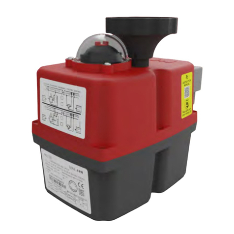
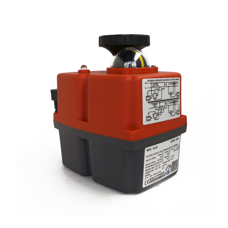
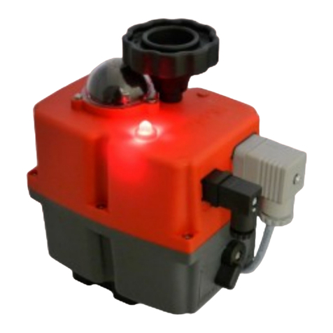
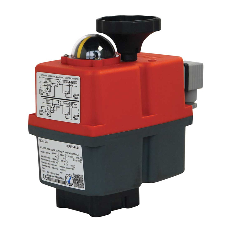
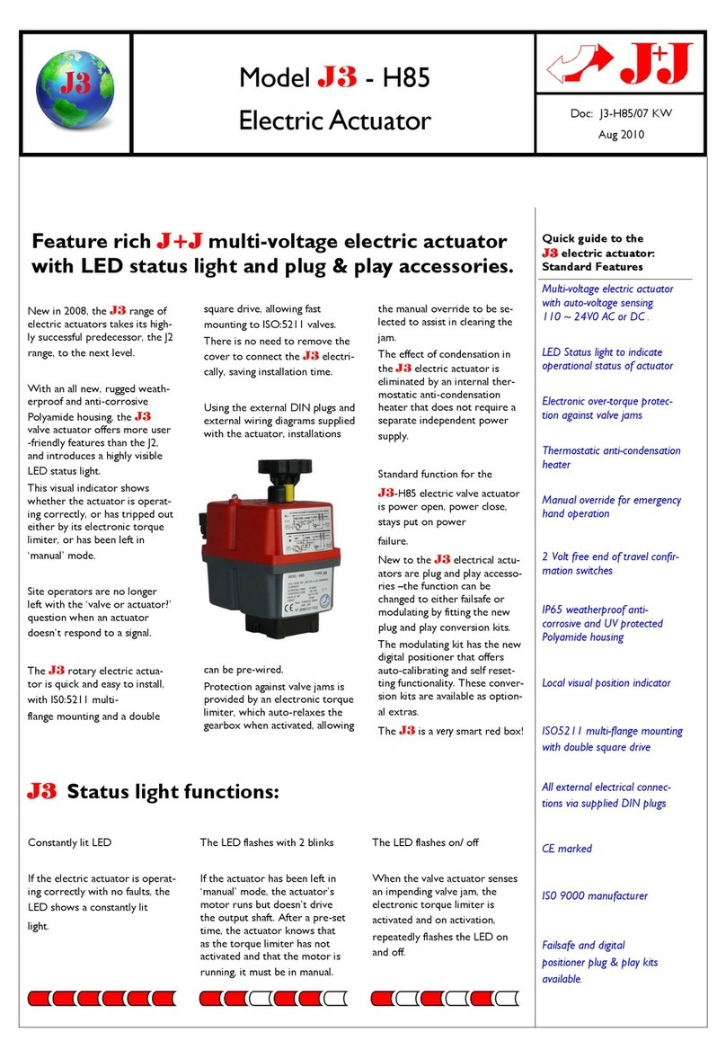
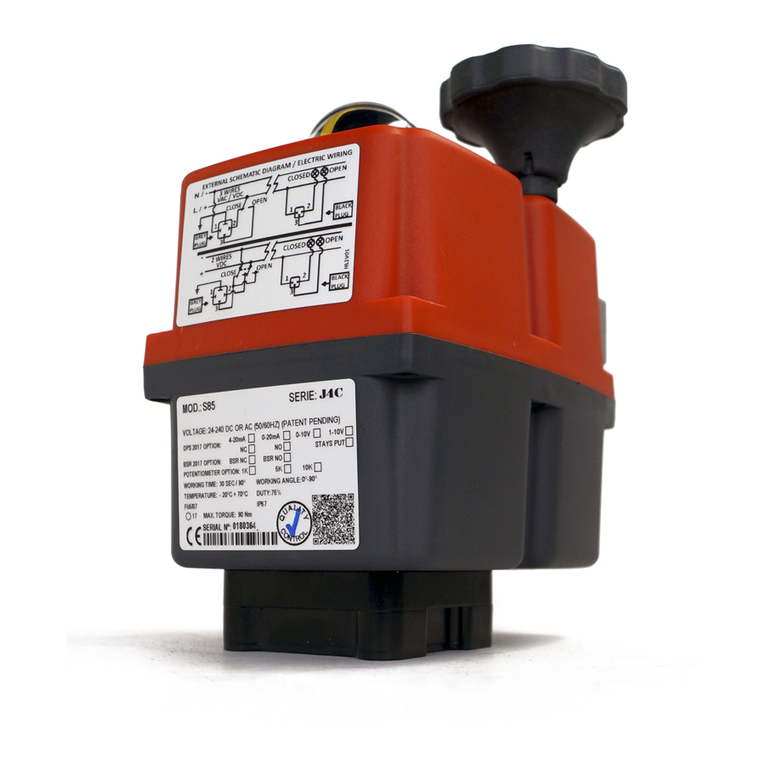
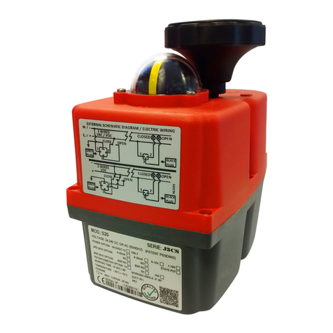
J+J J4M Series User manual

Handbook (EN) 23-03 V1
www.jjbcn.com
HANDBOOK

2
Index
HANDBOOK
INDEX
› 01. Actuator part list
• S2, S6, S10, B2, B6, B10
• S25, S40, B25, B40
› 02. J4M series
• Voltage
• Electrical Connectors
• ID Actuator Label
• Local Visual Position Indicator
• Emergency Manual Override Facility
• Table of consumptions
• External Connecting Diagram
› 03. Datasheet
• J4M 2
• J4M 6
• J4M 10
• J4M 25
• J4M 40
› 04. Bluetooth Interface Manual
› 05. Option
• Modbus
› 06. Guarantee
› 07. Contact

Index
3
01 ACTUATOR
PART LIST

4
Index
HANDBOOK / ACTUATOR PART LIST
MODELS: S2, S6, S10, B2, B6, B10
Position indicator
Power supply plug
Automatic/
manual lever
Manual override
Visual control of operation
Signal plug
Volt free
contact plug
ISO multiange

5
Index
HANDBOOK / ACTUATOR PART LIST
MODELS: S25, S40, B25, B40
ISO multiange
Manual override
Visual control of
operation
Signal plug
Volt free
contact plug
Position indicator
Power
supply plug
Automatic/
manual lever

Index
6
02 J4M SERIES

7
Index
HANDBOOK / J4M SERIES
J4M Electric actuators operate with the use of live electricity. It is recommended that only qualied electrical
engineers be allowed to connect or adjust these actuators.
VOLTAGE TO BE CONNECTED
All our actuators model S2 to S40 are ready to work from 24-240 VDC/VAC.
All our actuators model B2 to B40 are ready to work at 12 VDC/VAC ONLY.
ELECTRICAL CONNECTORS
Warning: Before connecting ensure that the voltage to be applied to the actuator is within the range shown on the
identication label. The supplied electrical connectors, used to connect to the actuator are DIN plugs. Ensure the
diameter of cable to be used conforms to the maximum and minimum requirements of the DIN plugs to maintain
water tightness (Fig.1).
Connector Small Black Big Grey or Black
Din43650/C EN175301-803 Form A
Model min. Ø max. Ø min. Ø max. Ø
J4M 2 to 10 5 mm 6 mm 8 mm 10,5 mm
J4M 25 to 40 -- -- 8 mm 10,5 mm
1. Gasket
2. Terminal strip
3. Cable xing screws
4. Housing
5. Washer
6. Grommet
7. Gland - nut
8. Fixing screw
9. Washer
10. Gasket
Read these instructions before connecting the actuator. Damage caused by non compliance of
these instructions is not covered by our warranty.
Warning: Ensure that the square rubber seal is in place
when xing each DIN plug to the actuator. Failure to do
so could allow water ingress and damage caused by this
installation error will invalidate any warranty. The DIN
plugs are xed to their respective bases on the actuator
housing with a screw. Do not over tight the screw (8)
when assembling (Max. 0.5Nm ).

8
Index
HANDBOOK / J4M SERIES
ID ACTUATOR LABEL
1 11
12
13
14
15
16
17
18
19
8
9
10
2
3
4
5
6
7
1. Actuator Model.
2. Voltage to be connected.
3. Actuator ready to bear between -20ºC / +70ºC.
4. Time/Turn.
5. Working angle.
6. Plate to x the valve to the actuator, following
ISO 5211.
7. Actuator with the IP67 protection.
8. Maximum operational torque.
9. Actuator serial number.
10. Bar code of the serial number.
11. Actuator series.
12. Duty: 75%.
13. QR code for manufacturing.
14. Actuator with CE certicate.
15. This product should not be disposed of as
unsorted waste.
16. UK Conformity Assessed.
17. Quality Control Conformity.
18. Country where the equipment was
manufactured.
19. DPS conguration

9
Index
HANDBOOK / J4M SERIES
LOCAL VISUAL POSITION INDICATOR
All J4M actuators are supplied with a local visual position indicator (Fig.6).
The OPEN position shows the indicator in BLACK and at the end of the stroke (max 14 turns) shows the full
indicator in RED.
EMERGENCY MANUAL OVERRIDE FACILITY
The J4M has 2 operating modes, automatic and manual, the required mode is selected by using a lever on the lower
half of the actuator housing (Fig 7).
The 2 positions are marked:
AUTO = Automatic operation
MAN = Manual operation
Warning: Do not rem ov e the selector lev er securing screw, as this will allow its internal m echanism to become
loose and will cause irreparable damage to the actuators gearbox. Removing this screw will invalidate the
warranty.
When “AUTO” position is selected: The hand wheel rotates automatically, it is very important not to block it,
otherwise the actuator could suffer unrepairable damages.
Fig. 6 OPEN Fig. 6 MAX. 14 TURNS

10
Index
HANDBOOK / J4M SERIES
Fig. 7 J4M 2,6 and 10 Fig. 7 J4M 25 and 40
J4M 2,6 and 10 J4M 25 and 40
When “MAN” function is selected:
1. The electronic system cuts the power to the motor after a few minutes.
2. The mechanical connection between the motor and the output shaft is disconnected.
3. The desired position can be achieved by using the hand wheel.
4. There are two ways to re-active the motor after being isolated whilst in “MAN” position:
a) Change from “MAN” mode to “AUTO”. Deactivate the supply voltage for a few seconds which resets the
actuator and it could operate automatically again.
Automatic - Manual
Position Indicator
Hand Wheel

11
Index
HANDBOOK / J4M SERIES
TABLE OF CONSUMPTIONS ON-OFF ACTUATOR
J4M S2 Consumption Minimum operational torque - 2 Nm Maximum operational torque - 5,5 Nm
Voltage Model A W A W
12 VDC S2 1,62 19,50 2,17 26,00
24 VDC S2 0,81 19,30 1,28 30,70
48 VDC S2 0,39 18,60 0,57 27,10
110 VDC S2 0,63 69,00 0,96 105,50
12 VAC S2 2,31 27,70 2,70 32,40
24 VAC S2 1,04 25,00 1,80 43,10
48 VAC S2 0,64 30,80 1,08 52,00
110 VAC S2 0,23 25,40 0,35 38,50
240 VAC S2 0,16 38,50 0,23 56,00
J4M S6 Consumption Minimum operational torque - 5 Nm Maximum operational torque - 9 Nm
Voltage Model A W A W
12 VDC S6 2,43 29,20 3,03 36,30
24 VDC S6 1,36 32,60 1,66 39,30
48 VDC S6 0,61 29,40 0,73 35,10
110 VDC S6 0,18 19,60 0,22 24,70
12 VAC S6 2,89 34,60 4,33 52,00
24 VAC S6 1,75 42,10 2,25 54,10
48 VAC S6 0,98 47,10 1,27 60,70
110 VAC S6 0,36 39,20 0,45 49,60
240 VAC S6 0,23 54,40 0,28 68,10
J4M S10 Consumption Minimum operational torque - 7 Nm Maximum operational torque - 15 Nm
Voltage Model A W A W
12 VDC S10 2,39 28,60 3,13 37,60
24 VDC S10 1,21 28,90 1,70 40,80
48 VDC S10 0,55 26,60 0,78 37,30
110 VDC S10 0,15 16,70 0,22 24,20
12 VAC S10 2,55 30,60 6,97 83,70
24 VAC S10 1,69 40,60 2,41 57,90
48 VAC S10 0,99 47,50 1,69 81,20
110 VAC S10 0,31 34,10 0,44 47,90
240 VAC S10 0,21 50,70 0,28 68,10

12
Index
HANDBOOK / J4M SERIES
TABLE OF CONSUMPTIONS ON-OFF ACTUATOR
J4M S25 Consumption Minimum operational torque - 10 Nm Maximum operational torque - 30 Nm
Voltage Model A W A W
12 VDC S25 3,08 37,00 7,46 89,60
24 VDC S25 2,20 52,90 3,53 84,70
48 VDC S25 0,96 46,10 1,66 79,60
110 VDC S25 0,35 38,00 0,59 64,90
12 VAC S25 5,16 61,90 10,11 121,30
24 VAC S25 2,70 64,80 4,58 110,00
48 VAC S25 1,55 74,30 2,12 101,70
110 VAC S25 0,58 63,90 1,03 113,50
240 VAC S25 0,51 122,00 0,77 185,30
J4M S40 Consumption Minimum operational torque - 16 Nm Maximum operational torque - 50 Nm
Voltage Model A W A W
12 VDC S40 3,27 39,30 9,85 118,20
24 VDC S40 2,04 49,10 3,87 92,80
48 VDC S40 0,91 43,70 1,85 89,00
110 VDC S40 0,32 35,60 0,66 72,10
12 VAC S40 4,37 52,50 12,04 144,50
24 VAC S40 2,48 59,40 5,43 130,40
48 VAC S40 1,35 64,80 2,65 127,10
110 VAC S40 0,61 67,00 1,19 130,90
240 VAC S40 0,48 115,60 0,84 202,80

13
Index
HANDBOOK / J4M SERIES
ON - OFF VAC / VDC
The power supply is connected to the grey “A” DIN plug.
• Negative PIN 3 + Positive PIN 2 = Actuator close
• Negative PIN 2 + Positive PIN 3 = Actuator open
• Earth/ground connection - Flat PIN
The volt free connection (conf. of position) black “B” DIN plug.
• Common PIN 1 + PIN 2 = Conrmation of close position
• Common PIN 1 + PIN 3 = Conrmation of open position
ON - OFF VAC / VDC
The power supply is connected to the grey “A” DIN plug.
• Neutral or negative PIN 1 + Phase or positive PIN 2 = Actuator close
• Neutral or negative PIN 1 + Phase or positive PIN 3 = Actuator open
• Earth/ground connection - Flat PIN
The volt free connection (conf. of position) black “B” DIN plug.
• Common PIN 1 + PIN 2 = Conrmation of close position
• Common PIN 1 + PIN 3 = Conrmation of open position.
EXTERNAL CONNECTING DIAGRAM
A
A
B
B
A
A
B
B
A
A
B
B
C
C
POSITIONER VAC / VDC
The power supply is connected to the grey “A” DIN plug
• Neutral or negative PIN 1 + Phase or positive PIN 2 = Power supply
• Earth/ground connection - Flat PIN
Input/output signal is connected to the black “C” DIN plug
• Negative PIN 1 + positive PIN 2 = Input signal
• Negative PIN 1 + positive PIN 3 = Output signal
The volt free connection - black “B” DIN plug
• Common PIN 1 + PIN 2 = Conrmation of close position
• Common PIN 1 + PIN 3 = Conrmation of open position
C= Instrumentation signal, NO VOLTAGE

14
Index
HANDBOOK / J4M SERIES
POSITIONER VAC / VDC ONLY OUTPUT
The power supply is connected to the grey “A” DIN plug
• Neutral/negative PIN 1 + Phase/positive PIN 2 = Close position
• Neutral/negative PIN 1 + Phase/positive PIN 3 = Open position
• Neutral/negative PIN 1 + Phase/positive PIN 2 + Phase/positive PIN 3 = Stop
Output signal is connected to the black “B” DIN plug
• Negative PIN 1 + positive PIN 3 = Positive = Output signal
The volt free connection - black “C” DIN plug
• Common PIN 1 + PIN 2 = Close conrmation of position
• Common PIN 1 + PIN 3 = Open conrmation of position
A
A
B
B
C
C
C= Instrumentation signal, NO VOLTAGE

Index
15
03 DATASHEET

16
Index
HANDBOOK / DATASHEET J4M 2
J4M 2 - GENERAL CHARACTERISTICS
Technical Data
Operation time unload 4 Sec / turn
Minimum operational torque 2 Nm / 17,70 lb/in
Maximum operational torque 5,5 Nm / 48,68 lb/in
Duty rating 75%
Maximum number turns 13.5
Conrmations Standard_Analogue: 2 Relays 24VDC 1Amp. (1 Open and
1 Close) / Optional: Digitals (1 Open and 1 Close)
Automatic heater 3,5 W
Big Plug EN 175301-803 FORM A
Small Plug DIN43650/C
Interface App and PC Program
Protection IEC 60529 rating IP67
Temperature -20ºC +70ºC / -4ºF +158ºF
ISO 5210 Plate Standard: F03/F04/F05 Optional: F07 *17 mm
DIN 3337 Female output drive Standard: *14 Optional: *9, *11 mm
Weight 1,9 kg
Materials Standard Optional
Body Anticorrosive Polyamide, Grey colour Polypropilene V0, Black colour
Cover Anticorrosive Polyamide, Red colour Polypropilene V0, Natural colour
Output drive Zamak, Zinc plated Zamak, TEFLON coated
Flange Zamak and Zinc plated Zamak and TEFLON coated
Main external shaft Anticorrosive Polyamide -
External screws Stainless Steel -
Gears Steel and Polyamide -
Visual position indicator Polyamide -
Dome Polycarbonate -
Note: Technical data are the same despite the different casings.
Manufacturer option
Actuator with Bluetooth
Congurations:
1)On-Off
2) Digital positioner (input / output) 4-20mA, 0-20mA,
0-10V or 1-10V
Electronic Data
Electronic Torque Limiter function
Electric motor 24VDC Brushless motor
Insulation Class B
(IEC 60034)
Service
S4
Voltage VDC/VAC 50/60Hz 0%/5%
S2 24-240 VDC/VAC
B2 12 VDC/VAC ONLY

17
Index
HANDBOOK / DATASHEET J4M 2
J4M 2 SIZES

18
Index
HANDBOOK / DATASHEET J4M 2
30
33
34
3535
37
38
32
39
41
43
44
45
37
50
52
53
40
36
MV J4S02
47
46
31
40
42
49
48
51
NÚMERO
CÓDIGO CANTIDAD
30
AP01357
1
31
AP00159
1
32
AP00161
1
33
AP01047
1
34
AP01361
1
35
AP00704
4
36
AP01106
1
37
AP00080
7
38
AP00376
1
39
AP01017
1
NÚMERO
CÓDIGO CANTIDAD
40
AP01028
2
41
AP00070
6
42
AP00057
1
43
AP00048
1
44
AP01195
1
45
AP01183
1
46
MM01369
1
47
MM00699
1
48
AP01198
AP01199
1
1
NÚMERO
CÓDIGO CANTIDAD
49
AP01194
1
50
AP01023
1
51
AP01056
1
52
AP00911
2
53
AP01000
1
A A
B B
C C
D D
E E
F F
4
4
3
3
2
2
1
1
EXPOLDED VIEW

19
Index
HANDBOOK / DATASHEET J4M 2
54
55
56
57
59
60
MV J4S2
61
63
62
58
65
66
58
62
58
64
62
58
67
68
NÚMERO
CÓDIGO
CANTIDAD
54
AP00794
1
55
AP01013
1
56
AP00991
1
57
AP01000
1
58
AP00014
4
59
AP00343
1
60
AP00031
1
61
AP00998
1
62
AP00032
3
63
AP00861
1
NÚMERO
CÓDIGO
CANTIDAD
64
AP01115
1
65
AP00312
1
66
AP00251
1
67
AP00960
1
68
AP00021
1
A A
B B
C C
D D
E E
F F
4
4
3
3
2
2
1
1
EXPOLDED VIEW

20
Index
HANDBOOK / DATASHEET J4M 2
EXPOLDED VIEW
26
27
28
29
MV J4S2
1
2
3
416
5
6
7
8
3
3
9
10
11
12
13
14
10
20
19
25
24
23
22
10
18
17
21
15
NÚMERO
CÓDIGO
CANTIDAD
1
AP00162
1
2
AP00083
1
3
AP00053
3
4
AP00345
3
5
AP00346
1
6
AP01002
1
7
AP01001
1
8
AP01003
1
9
AP00379
1
10
AP00541
11
NÚMERO
CÓDIGO
CANTIDAD
11
AP00455
1
12
AP00050
1
13
AP00044
1
14
MM00187
1
15
AP00037
1
16
AP00372
1
17
AP00023
1
18
AP00133
1
19
MM01382
1
20
MM00004
1
NÚMERO
CÓDIGO
CANTIDAD
21
MM00091
1
22
AP01098
4
23
AP01099
4
24
AP00068
2
25
AP00067
1
26
AP00457
1
27
AP00054
1
28
AP00056
1
29
AP00456
1
A A
B B
C C
D D
E E
F F
4
4
3
3
2
2
1
1
This manual suits for next models
5
Table of contents
Other J+J Controllers manuals
Popular Controllers manuals by other brands

ProMinent
ProMinent DULCOMETER Compact Assembly and operating instructions

Linear Technology
Linear Technology LTC4232 Demo Manual

Danfoss
Danfoss AMV 150 instructions

Armstrong
Armstrong AVR 235 Service manual

Paradise Datacom
Paradise Datacom ROLA-CHEM Pool Sentry M-3000 Assembly instructions

Ltech
Ltech LT-3900IR manual

HomeMatic
HomeMatic HM-ES-PMSw1-Pl-DN-R5 operating manual

Pego
Pego 200PEVS01 User and maintenance manual

Bosch
Bosch Rexroth IndraDrive CsDrive System with HCS01 instruction manual

Lexicon
Lexicon MC-1 owner's manual

Ex-Tech
Ex-Tech ZBW Series operating instructions

Kaysun
Kaysun KCT-03 SR Installation and owner's manual