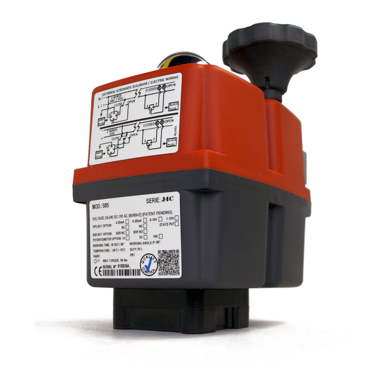
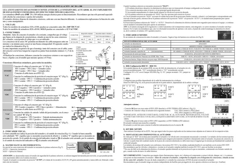
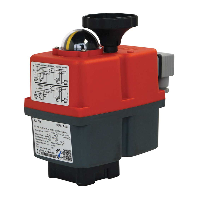
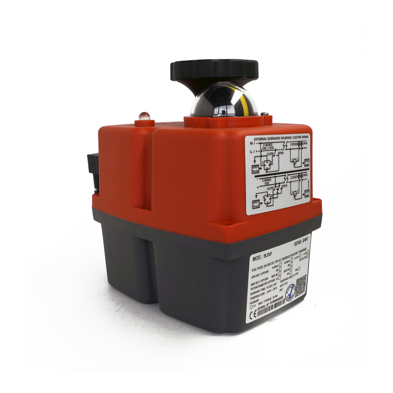
J+J J3-35 User manual

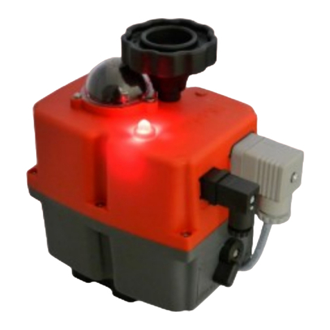
J3 Status light functions:
The LED flashes on/ off
When the valve actuator senses
an impending valve jam, the
electronic torque limiter is
activated and on activation,
repeatedly flashes the LED on
and off.
Constantly lit LED
If the electric actuator is operat-
ing correctly with no faults, the
LED shows a constantly lit
light.
The LED flashes with 2 blinks
If the actuator has been left in
‘manual’ mode, the actuator’s
motor runs but doesn’t drive
the output shaft. After a pre-set
time, the actuator knows that
as the torque limiter has not
activated and that the motor is
running, it must be in manual.
Aug 2010
Doc: J3-H85/07 KW
the manual override to be se-
lected to assist in clearing the
jam.
The effect of condensation in
the J3 electric actuator is
eliminated by an internal ther-
mostatic anti-condensation
heater that does not require a
separate independent power
supply.
Standard function for the
J3-H85 electric valve actuator
is power open, power close,
stays put on power
failure.
New to the J3 electrical actu-
ators are plug and play accesso-
ries –the function can be
changed to either failsafe or
modulating by fitting the new
plug and play conversion kits.
The modulating kit has the new
digital positioner that offers
auto-calibrating and self reset-
ting functionality. These conver-
sion kits are available as option-
al extras.
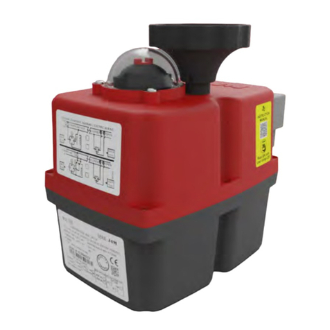
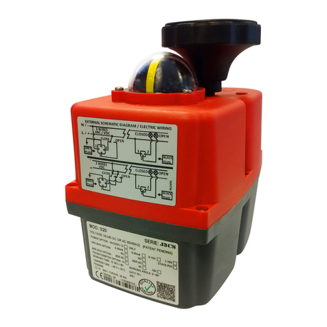
The J3 is a very smart red box!
Feature rich J+J multi-voltage electric actuator
with LED status light and plug & play accessories.
New in 2008, the J3 range of
electric actuators takes its high-
ly successful predecessor, the J2
range, to the next level.
With an all new, rugged weath-
erproof and anti-corrosive
Polyamide housing, the J3
valve actuator offers more user
-friendly features than the J2,
and introduces a highly visible
LED status light.
This visual indicator shows
whether the actuator is operat-
ing correctly, or has tripped out
either by its electronic torque
limiter, or has been left in
‘manual’ mode.
Site operators are no longer
left with the ‘valve or actuator?’
question when an actuator
doesn’t respond to a signal.
The J3 rotary electric actua-
tor is quick and easy to install,
with IS0:5211 multi-
flange mounting and a double
square drive, allowing fast
mounting to ISO:5211 valves.
There is no need to remove the
cover to connect the J3 electri-
cally, saving installation time.
Using the external DIN plugs and
external wiring diagrams supplied
with the actuator, installations
can be pre-wired.
Protection against valve jams is
provided by an electronic torque
limiter, which auto-relaxes the
gearbox when activated, allowing
Quick guide to the
J3 electric actuator:
Standard Features
Multi-voltage electric actuator
with auto-voltage sensing.
110 ~ 24V0 AC or DC .
LED Status light to indicate
operational status of actuator
Electronic over-torque protec-
tion against valve jams
Thermostatic anti-condensation
heater
Manual override for emergency
hand operation
2 Volt free end of travel confir-
mation switches
IP65 weatherproof anti-
corrosive and UV protected
Polyamide housing
Local visual position indicator
ISO5211 multi-flange mounting
with double square drive
All external electrical connec-
tions via supplied DIN plugs
CE marked
IS0 9000 manufacturer
Failsafe and digital
positioner plug & play kits
available.
Model J3 - H85
Electric Actuator

Specifications: J3 –H85
Materials of construction:
The J3 - H85 electric rotary actuator
Model J3 –H85 Electric Actuator
Visual indication of the
actuator’s operating
status is constantly
shown by a highly
visible LED light.
J3
Voltage range - automatically sensed by actuator 85-240 AC (1ph) or DC
Operating time (0-90° no load) 30 seconds
Maximum break torque 93.5 Nm / 827 lb.ins
Maximum operating torque (run/ reseat) 85 Nm / 752 lb.ins
Duty rating 75%
IP Rating (IEC 60529) IP65
Working angle Standard (on request) 90° (180° or 270° options)
Mounting ISO:5211 x DIN 3337 F05 & F07 x 17
Motor switches 2 x SPDT micro switches
End of travel confirmation (volt free) 2 x SPDT micro switches
Heater 4 W
Ambient temperature range -20° to +70°C -4 to +158°F
Electrical connecting plugs DIN 43650/ ISO4400 & C192
Consumption:
240V/1ph At maximum torque 0.09A
240V DC At maximum torque 0.10A
110V/ 1ph At maximum torque 0.22A
110V DC At maximum torque 0.17A
Weight 3.0 kg
Housing Anti-corrosive Polyamide
Fasteners Stainless steel
Gears Polyamide (speed reducing) & steel
Shaft Stainless steel
Output drive Zammac
Position indicator Glass filled Polyamide
Method of operation:
On receipt of a continuous power signal within the voltage range shown above, the motor in the J3
electric actuator runs and, via a flat gear system, rotates the output shaft. The motor is stopped by
internal cams striking micro switches. On receipt of a reversing continuous signal, the motor turns in
the opposite direction reversing the output drive.
Note: The power signal needs to remain on at all times to activate the thermostatic anti-condensation
heater. The volt free end of travel confirmation switches must NOT be used to cut the power. As they
are set ahead of the final motor stop position, cutting the power on receipt of the end of travel signal
will result in the J3 electric actuator stopping short of the full open or full closed position determined
by the motor switch settings.

The standard on-off
version can have plug
and play failsafe or
modulating kits retro-
fitted to convert the
function.
The modulating kit
contains a self
calibrating digital
positioner.
Dimensions: J3 - H85
Change of function retro-fit kits:
Failsafe option
This kit converts the electric actuator to a failsafe unit
using a BSR (Battery ‘Spring Return’) system that pro-
vides an alternative (battery) power supply to set the
actuator in the failsafe position should the main power
supply fail.
It can be configured normally open, or normally closed.
Modulating Option
Using the new self calibrating and self adjusting digital
positioning system, this kit converts the actuator to a
modulating electric actuator using either a 4-20mA or
0-10VDC control signal.
An output signal is provided as standard.
Model J3 - H85 Electric Actuator J3
LED status light
55mm
2.17”
73mm
2.88”
177mm
6.97”
196mm 7.72”
128mm 5.04”
Mounting F05 F07
ISO: 5211 50mm 70mm
Drive 17mm
Optional 14mm
Failsafe modulating option
Install both kits J3 Electric rotary actuator

J+J’s BSR system simply provides an alternative
power supply to drive the electric actuator to a pre-
set failsafe position in the event of a mains power
failure. It has no mechanical springs, it uses internal
battery power.
During normal operation the J3-BSR operates as a
power open - power closed electric actuator, simulta-
neously maintaining the industrial re-chargeable battery
at full strength from an internal trickle charging system.
The main advantage of J+J’s BSR system is that it is
more competitively priced compared to mechanical
spring return electric actuators, as the J+J failsafe
actuator has no mechanical springs to compress, or
solenoids to release them - the actuator is the same
size as that for an on-off version. This offers massive
savings compared to true mechanical spring return
electric actuators.
What it does and how it works
Aug 2010
Doc: J3/BSR/03/KW
Quick guide to the
J3 electric actuator
standard features :
Highly visible LED light gives
continuous actuator status
indication.
J3 L - 12-24V AC/DC
J3 H - 80-240V AC/DC
Multi-voltage electric actuator
with auto-voltage sensing:
Torque output: range:
25~95Nm Break
20~80Nm Reseat
Electronic torque limiter
Protects against valve jams
Anti-condensation heater
Manual override
All connections via external DIN
plugs ~ no need to remove cover
to connect
Volt free end of travel
confirmation switches
IP65 weatherproof housing
CE marked
Traceable sequential serial num-
bering system
Optional failsafe kit (Battery
Back-up) - actuator fails to safe
position on power failure
Optional modulating kit with
digital positioning system, either
0-10V or 4-20mA
Failsafe version ‘BSR’
Battery ‘Spring Return’
J3
The industrial battery is deliberately oversized
and whilst not necessary, can provide many
cycles at full load. This offers a degree of pro-
tection in the unlikely event that the battery
degrades and loses some charge.
In the event of a mains failure, if not already in
that position, an internal switch changes to
immediately draw battery power to drive the
actuator to the failsafe position.
Following a battery driven cycle the actuator
will need to charge for a short period to re-
place the energy used in the battery cycle.
This is particularly relevant if you intend to
use the J3 -BSR like a solenoid, eg: energise
open, fail close.
The BSR fits inside the J3 electric actuator
housing eliminating extra piggy-backed hous-
ings, making the J3 failsafe actuator very
compact and lightweight. It can be supplied as
a retro-fittable kit containing all the parts
needed to convert a standard on-off electric
actuator.

Charging data
Aug 2010
Doc: J3/BSR/03/KW
Quick guide to the
J3 electric actuator
standard features :
Highly visible LED light gives
continuous actuator status
indication.
J3 L - 12-24V AC/DC
J3 H - 80-240V AC/DC
Multi-voltage electric actuator
with auto-voltage sensing:
Torque output: range:
25~95Nm Break
20~80Nm Reseat
Electronic torque limiter
Protects against valve jams
Anti-condensation heater
Manual override
All connections via external DIN
plugs ~ no need to remove cover
to connect
Volt free end of travel
confirmation switches
IP65 weatherproof housing
CE marked
Traceable sequential serial num-
bering system
Optional failsafe kit (Battery
Back-up) - actuator fails to safe
position on power failure
Optional modulating kit with
digital positioning system, either
0-10V or 4-20mA
Failsafe version ‘BSR’
Battery ‘Spring Return’
J3
J3-20 J3-35 J3-55 J3-85 J3-140 J3-300
Initial minimum charge time
BEFORE being put into service
36 hrs
36 hrs
36 hrs
36 hrs
Not in
production
Not in
production
Nominal capacity ± 5% 800mA 800mA 800mA 800mA
Battery consumption per
Movement (W)
0.1
0.18
0.23
Minimum recharge time after
movement by battery
26 mins 26 mins 50 mins 65 mins
Configuration
The J3-BSR is factory supplied to fail closed on mains failure (normally closed) but can be configured to
fail open (normally open) simply by removing a jumper from the actuator PCB - see below.
A few seconds after a power cut, the J3’s LED will slowly flash and the actuator will be driven to the
fail safe position, the LED will continue to flash on-off for 3 minutes - during this time the battery pro-
vides power to the J3’s internal circuitry and anti-condensation heater. At the end of these 3 minutes, if
mains power has not been restored, the J3 completely shuts down and the LED goes out.
On resumption of mains power, conditional that the control signal has not changed during the power
outage, the actuator will reset to the position it saw at the moment of the power failure.
‘NC’ Normally closed jumper position
(factory standard)
‘NO’ Normally open jumper position
(jumper removed)
This manual suits for next models
6
Table of contents
Other J+J Controllers manuals