JTS RU-901Du User manual

Instruction Manual
UHF PLL
With JTS 2.4G RF Synchronizing Technology
R-901Du
2
Channel Receiver
RU-901Du /

One year product warranty
Warranty description
1. Be sure to put the warranty label indicating purchase date on the bottom of
equipment to ensure your interest in maintenance and service.
2. Product warranty, starting on the purchase date indicated on “warranty
label”, will last for one year; if the equipment does not have “warranty label”,
the warranty period is 15 months from the manufacturing date. If a micro-
phone is broken but not sent back with the equipment, the warranty period is
15 months from the manufacturing date of the microphone.
3. Within the warranty period, if the equipment is broken under normal use as
instructed in manual, please contact the original selling store for repair.
4. When the product is returned for repair, to facilitate proper determination of
cause of malfunction and of whether repair fee is needed, please ship back
the equipment and microphone together.
5. Within the warranty period, our company provides repair service at no cost
except for the following conditions that parts and repair may be charged:
a.Damages due to natural disaster or irresistible outside forces.
b.Damages due to drop, water, moisture, corrosion, foreign objects, missing
components.
c.The warranty does not cover consumable parts. (such as microphone
capsule, ball grille etc.)
d.Those without “warranty label” on equipment or with “warranty label” being
damaged and failing to identify warranty period.
6. Please keep the warranty properly. No replacement will be made if the war-
ranty is missing.
Equipment
serial number
Contact
number
Address
Purchase date
Selling store
stamp Be sure to put store stamp and ll in purchase date for the warranty to be
eective!
Product Model
Customer
name

1. Notes for system operations
2. Features
3. Specications
3-1 UHF PLL Dual-channel True Diversity receiver// RU-901Du
3-2 UHF PLL hand-held transmitter // R-4TH
4. Description of parts
4-1 UHF PLL Dual-channel True Diversity receiver // RU-901Du
4-2 UHF PLL hand-held transmitter // R-4TH
4-3 Accessories
5.Connecting
5-1 How to connect the receiver// RU-901Du
5-2 Transmitter installation // R-4TH
6. Instructions for use
6-1 How to use// RU-901Du
6-2 How to use// R-4TH
7. Notes for the product
1
1
2
2
3
4
4
7
9
11
11
12
13
13
18
20
INDEX

WIRELESS MICROPHONE SYSTEM
1
1. Notes for system operations
• Before connecting to power, make sure the voltage marked on
equipment is the same as that on the power socket.
• Do not leave the unit at where the humidity and temperature are high.
• Dry your hands before operating the system.
• Keep the unit away from re and heat source.
• Turn the volume to minimum at both the mixer and amplier before
setting up the system.
• Caution : The suitable environment for this product is with a temperature
between- 10°C (14°F) and +50°C (122°F).
2. Features
• 3rd generation True Diversity system.
• Transmission power selectable between '"High" and "Low".
• 6 groups are provided as default. Every group contains up to 23 default
channels.
• There are in total 1,441 channels to choose from.
• 36MHz bandwidth.
• The patented RF pairing for synchronized setting of all
parameters.
• Channel scan.
• Adjustable receiving sensitivity.
• Automatic microphone power o.
• Charging contact ready.

2
3. Specications
3-1 UHF PLL Dual-channel True Diversity receiver // RU-901Du
Frequency Oscillation Mode Phase-locked loop (PLL)
Carrier Frequency Range 470~608MHz
Remoset Frequency 2.4G RF
Diversity True diversity
Bandwidth 36MHz
Signal/Noise Ratio >105dB(A)
Total Harmonic Distortion (Thd) <0.6%@1KHz
Receiving Sensitivity -95dBm,S/N>80dB
Image Rejection Ratio >80 dB
Frequency Response 50Hz~16KHz±2dB
Antenna Type 1/2λ BNC detachable
Antenna Booster Power DC12V/100mA
Function Display By LCD
Contents Of Display
Group, channel, frequency, battery level, antenna A/
B, muting level, AF indication, RF indication, channel
scanning, output level attenuation, volume indication
Control Functions
Power, group, channel, frequency, muting level, button
lock, volume, output attenuation (XLR), scan ,Mix
Output
Audio Frequency Output Level(MAX) Ø6.3 Phone Jack:+4dBu
XLR Jack:+10dBu(Line)、-10dBu(MIC)
Audio Frequency Output Impedance 600Ω
Muting Noise muting and tone code locking
Output Port 2 x balanced XLR jack
2 x unbalanced Ø6.3 jack
Power Supply 100~240VAC
Dimension (Mm) 485mm (W) x45mm (H) x 260mm (L)

WIRELESS MICROPHONE SYSTEM
3
3-2 UHF PLL hand-held transmitter //
Frequency oscillation Phase-locked loop, PLL
Carrier frequency 470~608MHz
Bandwidth 36MHz
Paring RF Remoset
RF power output Low / High
RF stability <±10KHz@Fc
Modulation frequency
deviation ±48KHz
Spurious Emissions <-50dBc
LCD display
Group, channels, frequency, mute, input level
attenuation, sensitivity adjustment, power
indication, Device ID
Controls
Power, mute, groups, channels, frequency,
sensitivity adjustment, input level attenuation,
transmission power, key lock
Battery AA Alkaline battery x 2
Charging Yes
Dimension 265mm L x 51.2mm W x 51.2mm H
Remark Specifications provided above may be slightly
different from the product without further notice.

4
4. Description of parts
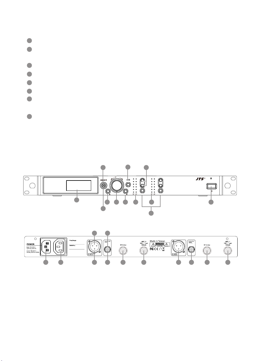
4-1 UHF PLL Dual-channel diversity receiver( True Diversity ) // RU-901Du
Front panel
5
6
7
8
1
4
2
3
Power ON/OFF:
ON:push once to turn on.
OFF:push and hold until ''Power OFF'' is shown on the LCD to turn o.
EXIT: Push exit to cancel a selection or exit from the current menu when RU-
901Du is in the ''setting menu.''
Rotary Switch: when in the ''function menu,'' turn the switch to select the
desired function; push the switch (or SETUP) to enter the selection and spin the
switch to select the setting. Push [SETUP] to save the setting.
SETUP: Push and hold for 2 seconds to enter the“setting menu.” Push SETUP to
save the setting once the selection and setting are made according to
''3. Rotary Switch.''
RF : this allows user to synchronize the transmitter after modifying a
parameter. Push “ ” to synchronize the settings to the transmitter.
Remoset indicator: this shows the current pairing status. It ashes rapidly
when data is being transmitted and the ashing stops when the synchronization
is completed. However, the ashing slows down if synchronization fails after a
period of time of pairing attempt.
LCD display: See ''Receiver LCD display instructions.''
AF: indicates the current strength of audio frequency signals.
RF: indicates the current strength of radio frequency signals.
Key lock: push and hold for 2 seconds to lock all keys, and again to unlock.
Volume keys: push▲/▼keys to adjust the volume between 0 and -31dB.
Selection key: push this button
a. Push SETUP to enter the setting for the selected channel for parameter
settings.
b. Push REMOSET to transmit the setting data to the transmitter in this
selected channel.
9
10
11
12
WIRELESS MICROPHONE SYSTEM
5
Front panel
Rear panel
Rear panel
3 3
5 5
7 78 8
2
46
1
Power : AC power 100~240VAC
AC power outlet(for cascading): it allows power connection to next receiver
with an extension AC power cable.
XLR audio jack: balanced audio signal output
XLR audio jack: balanced audio signal output after mixing
Ø6.3 audio output jack: unbalanced audio signal output
Ø6.3 audio output jack: unbalanced audio signal output after mixing
RF A (or B) Out: RF signal output socket(for cascading): Provide RF signal to next
receiver.
Antenna A (B) input terminal: BNC antenna input jack that also provides
DC12V/100mA output.
1
2
3
4
5
6
7
8
R -901Du
EXITSETUP
2
Channel Receiver
PUSH / CONTROL
SEL. SEL.
CH1 CH2
14
7
5
923
10
12
611
8

6
2
11
10
7
3
65
4
89
3
4
6
7
2
5
1:Antenna Selection A/B. The Receiver is mute.
: Transmitter Battery Level
:Frequency (Group/Channel)
: Frequency
: Key Lock (Key Lock ON)
: Volume
: Output attenuation ON
Content Displayed under the Non-Setting Mode:
8
9
10
Setup Menu
RX1: Set the Receiver's Channel 1. RX2: Set the Receiver's Channel 2.
1: Set the Receiver's Channel 1. 2: Set the Receiver's Channel 2.
520.325
WIRELESS MICROPHONE SYSTEM
7
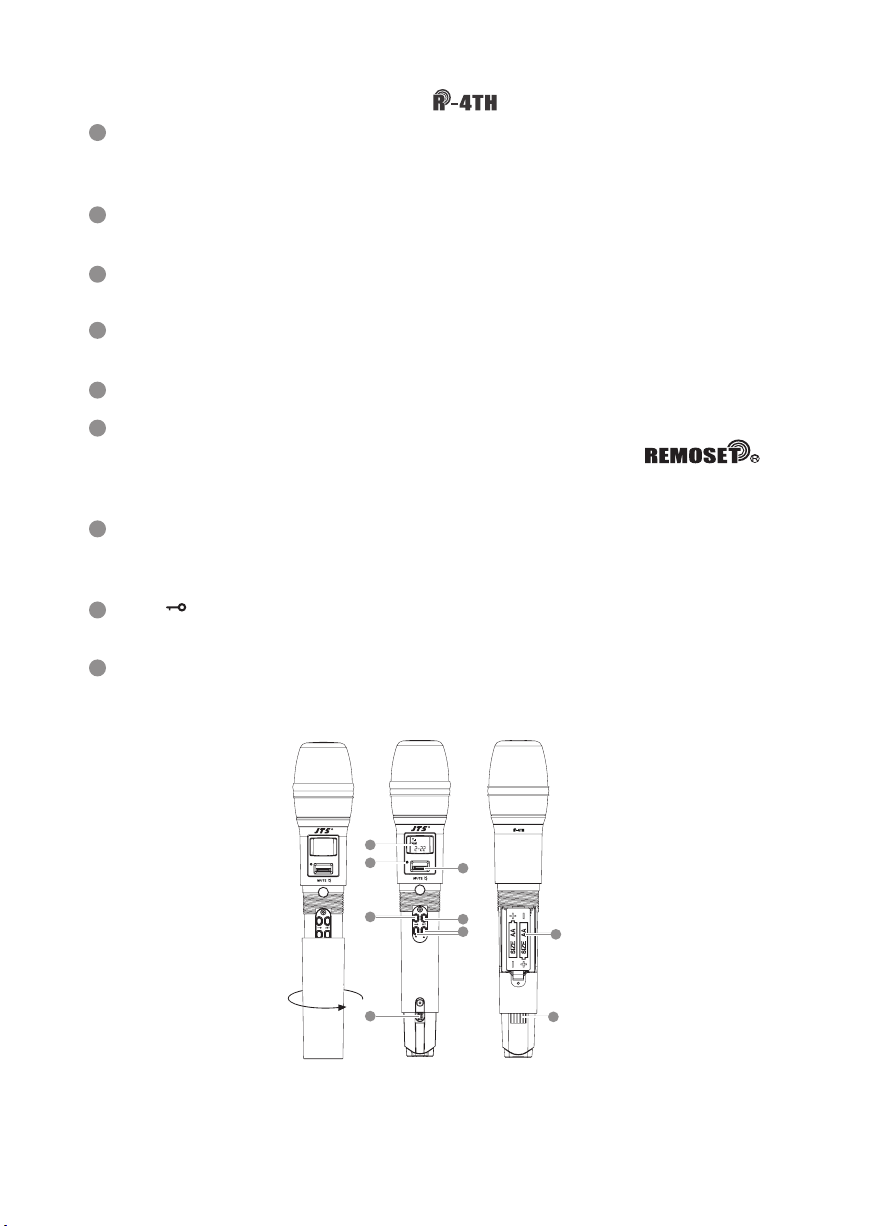
Power ON/OFF:push once to turn on. Push and hold for 2 seconds while
the power is on to turn off. While the power is on, a quick push of this
button will show the Device ID on the LCD display.
Mute:switch up to talk and down to mute while the power is on. If the
power is off, switching up from mute will turn the microphone on.
Battery compartment:it holds 2 UM3, AA 1.5V Alkaline batteries or MiNH
rechargeable batteries.
LED indicator:it shows the microphone's status, including battery power,
mute and pairing.
LCD display:it shows the parameter settings of transmitter.
SET:for parameter settings, including frequency, group, channel,
sensitivity, transmission frequency, auto off time, Device ID ,
function (ON/OFF).
Up/down selection keys:they are used with ''SET'' to change parameter
settings. Before entering the setting mode, a quick push will show the De-
vice ID on the LCD display.
LOCK :push and hold ''LOCK'' for 2 seconds to lock and again to unlock.
Under ''LOCK'' status MUTE function is still valid.
Charging contact module: if rechargeable batteries are used, charging is
possible with the matching charger.
4-2 UHF PLL handheld transmitter //
1
42
3
9
5
6
7
8
1
4
2
3
9
5
6
7
8
Other manuals for RU-901Du
1
This manual suits for next models
1
Table of contents
Other JTS Receiver manuals


