JUKI MCS-1500 User manual

SERVICE MANUAL
No.00
40178060
3-Needle, 2/3/4-Thread Cover Stitch Sewing Machine
MCS-1500

CONTENTS
Specications ............................................................................................................ 1
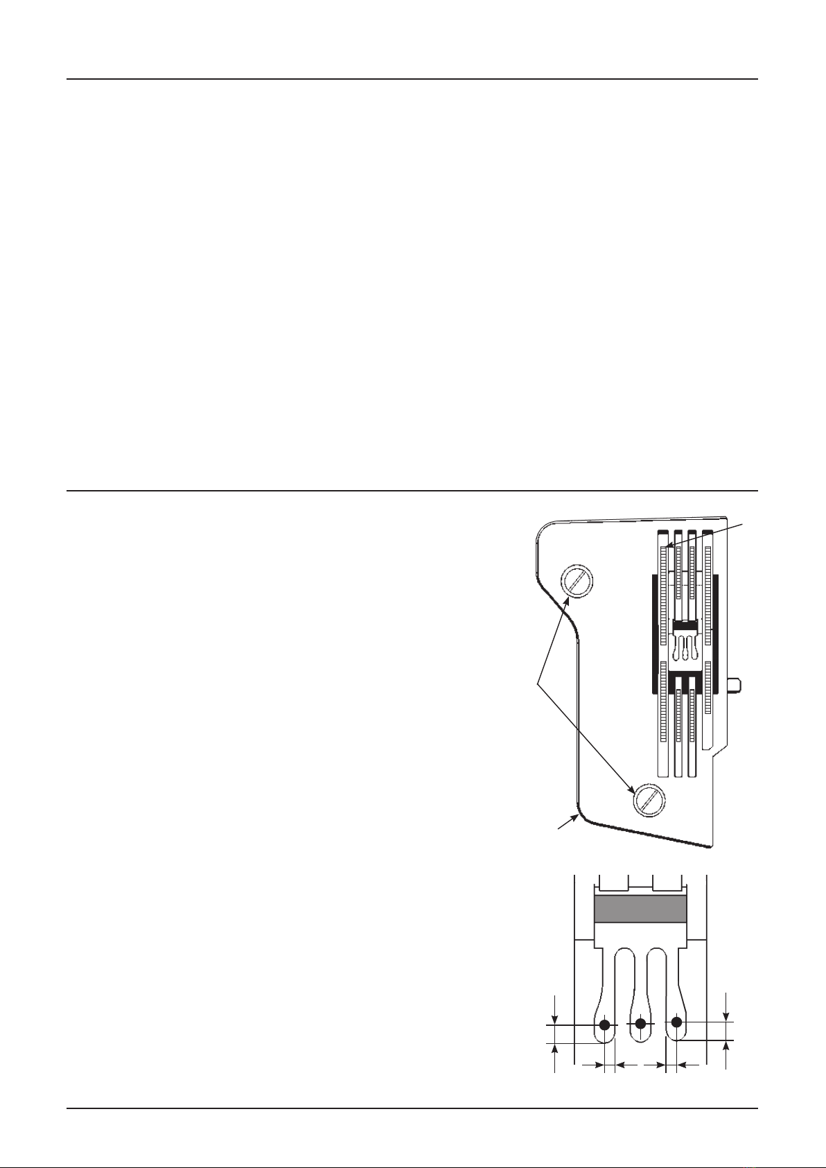
1.Installationofthethroatplate .............................................................................. 1
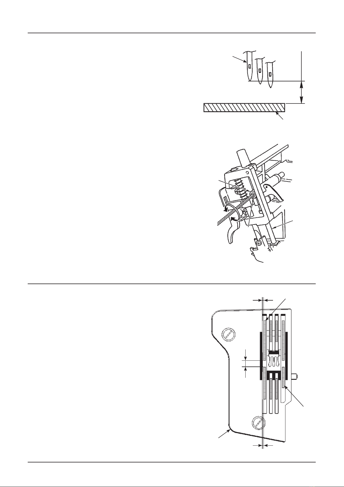
2.Heightoftheneedlebar........................................................................................ 2
3.Positionofthefeeddog........................................................................................ 2
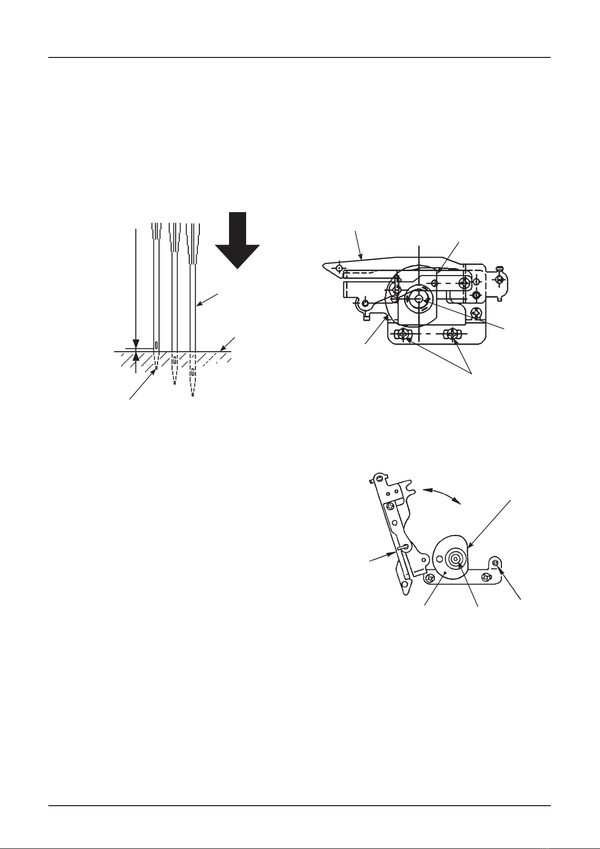
4.Heightofthefeeddog........................................................................................... 3
5. Feed dog timing..................................................................................................... 4
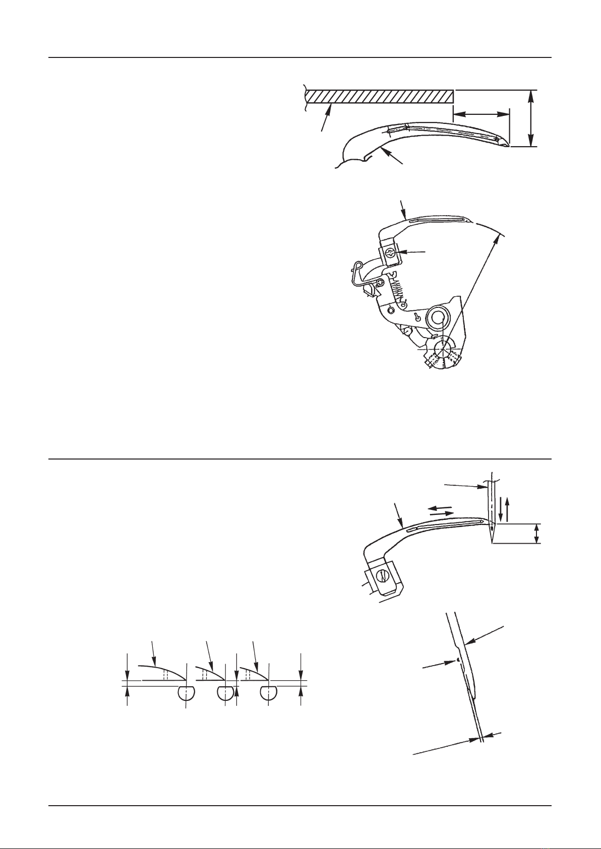
6.Positionofthebalanceweightsandcams ......................................................... 4
7.Radiusofthedouble-chainlooper....................................................................... 5
8.Adjustmentofthedouble-chainlooperandtheneedles................................... 5
9.Installationoftheneedleguards.......................................................................... 7
10.Positionofthedouble-chainlooperthreadtake-up ........................................ 8
11.Positionofthedouble-chainlooperthreadtake-upguide.............................. 9
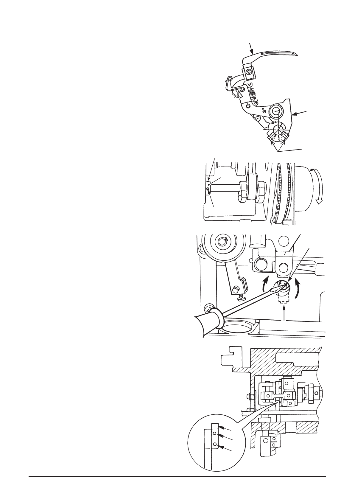
12.Positionofthetensionreleasemechanismofthetensioncontroller ........ 10
13.Heightandlateralpositionofthepresserfoot............................................... 11
14.Threadtensioncontrols.................................................................................... 12
15.Positioningthethreadtake-upspring............................................................. 13
WARNING :
Toavoidtheriskofre,electricshock,injurytopersonsordamagetocomponents,
especiallykeepthefollowing:
• When disassembling, assembling or adjusting the sewing machine, remove the power plug.
• When assembling, be careful about the electrical cord being caught with other components,
damage to the covered parts of the cord or miswiring.
• When replacing the part(s), use the genuine part(s).

– 1 –
Specications
No.
1.
2.
3.
4.
5.
6.
7.
8.
9.
10.
11.
12.
13.
14.
15.
16.
Items
No of needle and threads
Needle
Overedge width
Stitch length
Differential feed ratio
Needle bar stroke
Feed dog height
Presser foot height
Light
Power switch
Motor
Sewing speed
Driving system
Machine size
Machine weight
Foot control
Description
3-needles 4-threads, 2-needles 3-threads (for covering)
1-needle 2-threads (for double-chain)
130/705H #80 (#70 - #90)
5.0 mm (for covering)
1.0 - 4.0 mm
Stretching: 1 : 0.7 Shirring: 1 : 1 - 1 : 2
27 mm
Standard 1.3 mm
8 (+0/-0.6) mm
UL/CSA 15 Watt (built-in), VDE/SAA/GB 10 Watt (built-in)
2-step rocker switch
built-in, 240V, 120V, 230V, Input 90W
Up to 1,350 sti/min
Timing belt, Machine rotates in the forward (normal) direction
280 (W), 335 (D), 285 (H) mm
6.8 kg
Electronic type
1. Installation of the throat plate
1.1. Checking items:
1Throat plate
2Setscrew
3Feed dog
- Check that needles are laterally equidistant with respect to the throat
plate slot (A, B).
- Check that the distance between the needle center and the front
edge of the throat plate slot is 1.2 mm (C).
2
1
3
1.2. How to perform adjustment:
- Perform the adjustment of the needle entry by moving the throat
plate.
- Loosen the setscrews 2of the throat plate and adjust the following:
a) The feed dog teeth are parallel to the slots in the throat plate.
b) The needles are spaced equidistantly to the slots in the throat plate (A,
B).
c) The distance between the needle center and the front edge of the
throat plate slot is 1.2 mm (C).
- Retighten the setscrews 2.
(A)=(B)
(A) (B)
1.2 mm
(C)
1.2 mm
(C)

– 2 –
2.Heightoftheneedlebar
2.1.Checkingitems:
1Left hand needle
2Throat plate
- Check that the distance between the throat plate surface and
the left hand needle point with the needle bar at the highest
point of its stroke is 11.4 mm (A) when using needle system
130/705H.
2.2.Howtoperformadjustment:
- Allow the needle bar (D) to reach its highest position.
- Loosen the setscrew (B) of the needle bar connection (C)
slightly.
- Move the needle bar (D) up or down to make adjustment.
- Retighten the setscrew (B).
(D)
(B)
(C)
2・
1
(A)
11.4 mm
3.Positionofthefeeddog
3.1.Checkingitem:
1Main feed dog
2Sub feed dog
3Throat plate
- Check that the feed dog and the slot in the throat plate are
parallel with each other.
- Check that there is a clearance on the left side of the feed dog
and the throat plate of 0.2 mm (A).
- Check at the most-advanced position in max. main feed and
min. sub-feed the clearance between the main feed dog and
sub-feed dog is 1.0 mm (B).
2
1
3
(A) 0.2 mm
1.0 mm
(B)
(A) 0.2 mm

– 3 –
3.2.Howtoperformadjustment:
- Loosen the setscrews (D) of the sub feed dog.
- At the most advanced position in max. main feed and min. sub
feed move the sub feed dog back and forth and perform adjust-
ment so that the clearance between the main feed dog and the
sub feed dog is to be 1.0 mm (B).
- Retighten the setscrews (D).
(D)
4.Heightofthefeeddog
4.1.Checkingitems:
1Front end of feed dog
- Check that the feed dog in its highest position at stitch
length 2.5 is 1.3 mm higher than the throat plate sur-
face (A).
4.2.Howtoperformadjustment:
- Set the feed dog (A) in its highest position.
- Loosen the setscrew (C) from the eccentric stud (B).
- Turn the eccentric stud (B) to perform adjustment.
- Retighten the setscrew (C).
1
1.3 mm
(A)
(B)
(C)
(A)

– 4 –
5. Feed dog timing
5.1.Checkingitems:
1Left hand needle
2Throat plate
3Feed dog
- Check that the needle point of the left hand needle and the
teeth points of the feed dog are at the same time ush with the
surface of the throat plate when feed dog and the needle are
in their upward stroke at stitch length 2.5.
5.2.Howtoperformadjustment:
- Loosen the setscrews (A).
- Rotate the feed excenter cam (B) to make adjustment.
- Retighten the setscrews (A).
2
1
3
(B)
(A)
6. Positionofthebalanceweightsandcams
1Main shaft
2Feed cam
3Double-chain osc.cam
4First setscrew is alined at the position of setscrew
number 10
5Space 0 ~0.05 mm
6Lower looper cam
3
4
5
6
7 8
9
12!1
!2 !0
7First setscrew is alined at the position of setscrew
number 10
8Lower balance weight
9Needle bar driving cam
!0 First setscrew
!1 Same level
!2 Space 0.2 mm

– 5 –
7.1. Checking items:
1Double-chain lopper
2Setscrew of double-chain looper
3Throat plate
- To the right-most position of the double-chain looper.
Check that the distance between double-chain looper
blade point and the throat plate top surface is 15.1 mm
(A).
(Distance from the center of the double-chain looper
shaft to the double-chain looper blade point is 62.5 ±
0.15 mm).
7.2. How to perform adjustment:
- Loosen the setscrew 2of the double-chain looper.
- Move the double-chain looper up or down to make
adjustment 1.
- Retighten the setscrew 2.
7. Radius of the double-chain looper
2・
1
62.5 ± 0.15 mm
(A)
1
3
(15.5 mm)
15.1 mm
8. Adjustment of the double-chain looper and the needles
8.1. Checking items:
1Double-chain looper
2Needle
- Check the following distance when the double-chain looper
blade point meets the right side of the left needle.
(With both timing of the needle going up and down)
- Distance between the double-chain looper blade point and the
needle point is 6.3 mm (A).
- Check that the clearance between the double-chain looper
blade point and all needles is 0 ± 0.05 mm (B).
2
1
2
1
(B)
(A)
6.3 mm
0 ± 0.05 mm
1
11
(B)
(B)
Left
needle
Right
needle
Center
needle
(B)

– 6 –
1
(D)
(C)
8.2.Howtoperformadjustment:
Howtoadjustthedistanceandclearancebetweenthedou-
ble-chainlooperbladepointandtheneedle.
- Loosen the setscrews (C) of the double-chain looper support
arm.
- Move the double-chain looper support arm (D) back or forth,
left or right to make adjustment.
- Retighten the setscrews (C).
8.3.Howtoperformadjustment:
Howtoadjustthemeetingtimingofthedouble-chain
looper and the needle.
- Loosen the setscrews (F) of the lower looper cam (E).
- Rotate the lower looper cam (E) to make adjustment.
- Retighten the setscrews (F).
(G)
(H)
(E)
(F)
(F)
8.4.Howtoperformadjustment:
Howtoadjusttheclearancebetweenthedouble-chain
looperbladepointandtheneedle.
(Fineadjustment)
- Loosen the setscrews (H) of the eccentric stud (G).
- Turn the eccentric stud (G) left or right to make ne adjust-
ment.
- Retighten the setscrews (H).
8.5.Howtoperformadjustment:
Howtoadjusttheclearancebetweenthedouble-chain
looperbladepointandtheneedle.
(Differenceadjustmentoftherightneedleclearance
andtheleftneedleclearance.)
- Loosen the setscrews (I) of the Double-chain osc.cam (J).
- Rotate the Double-chain osc.cam (J) to make adjustment.
- Retighten the setscrews (I).
(J)
(I)
(I)

– 7 –
9.1.Checkingitem:
1Front needle guard
2Rear needle guard
3Setscrew
4Needle 130/705H size 80
5Setscrew
- Check that the clearance (A) of 0.05 - 0.1 mm is provided between
the needle and the rear needle guard.
- Check that the clearance (B) of 0 ± 0.15 mm is provided between
the needle and the front needle guard.
9.Installationoftheneedleguards
9.2.Howtoperformadjustment:
- Loosen the setscrew 5.
- Make the adjustment by moving the rear needle guard 2back or
forth.
- Retighten the setscrew 5.
- Loosen the setscrews 3.
- Move the needle guard 1, 2 to make the adjustment (B).
- Retighten the setscrews 3.
3
1
2
0 ± 0.05 mm (B)
4
1
2
5
0.05 - 0.1 mm (A)
4

– 8 –
10.1.Checkingitems:
1Double-chain looper thread take-up
2Double-chain looper thread take-up guide
3Setscrew of double-chain looper thread take-up
4Setscrew of double-chain looper thread take-up guide
- Check that the at part of the double-chain looper thread take-up 1is in its vertical position, when the needle
bar is position (A).
10.Positionofthedouble-chainlooperthreadtake-up
2
Needle bar position (A):
(A) is a position of the state of the following
gure, when a needle bar falls.
0 - 0.5 mm
Needle
Throat plate
at part
1
4
3
Left needle
10.2.Howtoperformadjustment:
- Loosen the setscrew 4and swing up the double-chain looper
thread take-up guide 2.
- Loosen the Setscrew 3of the double-chain looper thread
take-up 1.
- Turn the double-chain looper thread take-up 1to make adjust-
ment.
- Retighten the setscrew 3.
- Move the double-chain looper thread take-up guide 2down
and retighten the setscrew 4.
2
134
at part

– 9 –
11.1.Checkingitems:
1Double-chain looper thread take-up
2Double-chain looper thread take-up guide
3Double-chain looper thread take-up base plate
4Setscrews of double-chain looper thread take-up base
plate
5Shaft
- Check that the distance from the shaft 5 to the at side
of the double-chain looper thread take-up 1is 37 mm (A),
when the at side of the double-chain looper thread take-
up 1is in its vertical position.
11.2.Howtoperformadjustment:
- Loosen the setscrews 4of the double-chain looper
thread take-up base plate 3.
- Move the double-chain looper thread take-up base plate
3to make adjustment.
- Retighten the setscrews 4.
11.Positionofthedouble-chainlooperthreadtake-upguide
37 mm (A)
4
3
5
21

– 10 –
12.Positionofthetensionreleasemechanismofthetensioncontroller
12.1.Checkingitems:
1Tension release actuating plate
2Support shaft
3Setscrew
4Cam hole for the support shaft
- Check, if the tensions are released, when:
・ the presser foot is lifted
・ the tension dials are set on No.4
A clearance of 0.4 - 0.8 mm should appear between the
tension discs.
12.2.Howtoperformadjustment:
- Remove the front cover.
- Loosen the setscrew 3of the tension release actuating
plate 1.
- Move the tension release actuating plate 1left or right
to perform adjustment.
- Retighten the setscrew 3.
2
13
4

– 11 –
13.Heightandlateralpositionofthepresserfoot
13.1.Checkingitem:
1Throat plate
2Chain stitch presser foot
- Raise the presser foot using the lifting lever and check
that the distance between the throat plate surface and the
presser foot sole is 8 (+0/-0.6) mm (A).
- Check that the presser foot is parallel to the feed dog slot in
the throat plate.
13.2.Howtoperformadjustment:
- Raise the presser foot by lifting the lever.
- Loosen the setscrew of the presser bar guide bracket (B).
- Move the presser bar up or down and turn it to make adjust-
ment (C).
- Retighten the setscrew (B).
(B)
(C)
(A)
2
1

– 12 –
14. Thread tension controls
14.1. Checking item:
- Using a No.120 polyester spun thread (saba120c), check that
sewing results are good with tension settings between 3 and 5
(A) this by sewing a cover stitch formation.
- Check the specied tension values by using the tension gauge
and a No.120 polyester spun thread (saba120c white color).
・
Left needle tension (B) 35 - 45g
・
Center needle tension (C) 40 - 50g
・
Right needle tension (D) 55 - 65g
14.2. How to perform adjustment:
- Disassemble the thread tension controls.
- Remove tension dial scale 1.
- Loosen and remove the nut 2.
- Remove part 3to 8.
- Turn the nut 9 until the specied tension value is obtained.
- Remount the parts 8to 6.
- Mount the tension dial 6with indicator !7 at position 4, to
match No.4 on the dial scale 1.
(A)
(B) (C)
(D)
6
!7
1
1
2
3
4
5
6
7
8
9
!0
!1
!2
!3
!4
!5
!6

– 13 –
15.Positioningthethreadtake-upspring
- Left needle tension (A)
- Center needle tension (B)
- Right needle tension (C)
(C)
(A) (B)
4.8 - 5.4 mm
10.1 - 10.6 mm
6.2 - 6.6 mm
Position 4
Position 4
Position 6
2 - 2.5 mm 5 - 5.5 mm
0 mm

2-11-1, TSURUMAKI, TAMA-SHI,
TOKYO, 206-8551, JAPAN
PHONE : (81)42-357-2341
http://www.juki.com
000416
Copyright © 2016 JUKI CORPORATION
• All rights reserved throughout the world.
*ThedescriptioncoveredinthisServiceManualissubjecttochangeforim-
provementofthecommoditywithoutnotice.
Other manuals for MCS-1500
1
Table of contents
Other JUKI Sewing Machine manuals

JUKI
JUKI TL-98E User manual

JUKI
JUKI AMS-210ENHL2210/TF10S User manual

JUKI
JUKI DNU-1541-7 User manual

JUKI
JUKI LK-1900B/IP-420 User manual

JUKI
JUKI MO-2000QVP User manual

JUKI
JUKI MS-1190 User manual

JUKI
JUKI UnionSpecial 35800BLWG Setup guide

JUKI
JUKI SC-500 Quick start guide

JUKI
JUKI MEB-3810N Series User manual

JUKI
JUKI MO-655 User manual

JUKI
JUKI TU-273 User manual

JUKI
JUKI LU-2828NV User manual

JUKI
JUKI HZL-35Z User manual

JUKI
JUKI HZL-60 CE User manual

JUKI
JUKI MO-644 User manual

JUKI
JUKI SC-910N Quick start guide

JUKI
JUKI MO-654DE User manual

JUKI
JUKI AMS-210EN/IP-420 User manual

JUKI
JUKI MO-6900 Series User manual

JUKI
JUKI LU-1565N User manual