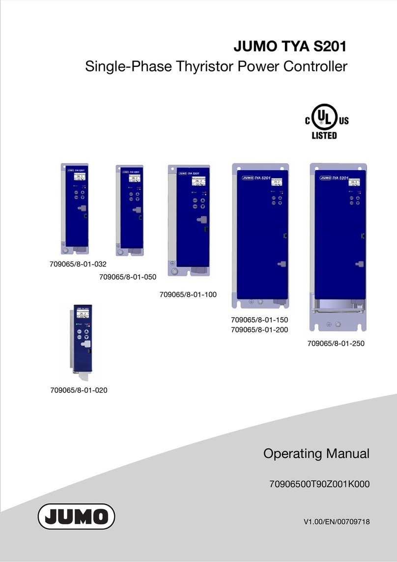
JUMO exTHERM-DR User manual

V3.00/EN/00644471
JUMO exTHERM-DR
Two-State Controller According to ATEX and IECEx
Operating Manual
70105500T90Z001K000
Type 701055/8-23-044 Type 701055/8-23-045

Operating overview


Content
Operating overview . . . . . . . . . . . . . . . . . . . . . . . . . . . . . . . . . . . . . . . . . . . . . . . . . . . . . . . . . . 2
1 Brief description . . . . . . . . . . . . . . . . . . . . . . . . . . . . . . . . . . . . . . . . . . . . . . . . . . . . . . . . . . . 10
1.1 Safety information . . . . . . . . . . . . . . . . . . . . . . . . . . . . . . . . . . . . . . . . . . . . . . . . . . . . . . . . . . . . . . . .11
2 Identifying the device version . . . . . . . . . . . . . . . . . . . . . . . . . . . . . . . . . . . . . . . . . . . . . . . . 12
2.1 Scope of delivery . . . . . . . . . . . . . . . . . . . . . . . . . . . . . . . . . . . . . . . . . . . . . . . . . . . . . . . . . . . . . . . . .13
2.2 Device software versions . . . . . . . . . . . . . . . . . . . . . . . . . . . . . . . . . . . . . . . . . . . . . . . . . . . . . . . . . . .14
2.3 Fabrication number . . . . . . . . . . . . . . . . . . . . . . . . . . . . . . . . . . . . . . . . . . . . . . . . . . . . . . . . . . . . . . .14
2.4 Service addresses . . . . . . . . . . . . . . . . . . . . . . . . . . . . . . . . . . . . . . . . . . . . . . . . . . . . . . . . . . . . . . . .14
3 Mounting . . . . . . . . . . . . . . . . . . . . . . . . . . . . . . . . . . . . . . . . . . . . . . . . . . . . . . . . . . . . . . . . . 16
3.1 Dimensions. . . . . . . . . . . . . . . . . . . . . . . . . . . . . . . . . . . . . . . . . . . . . . . . . . . . . . . . . . . . . . . . . . . . . .16
3.2 Mounting site, DIN-rail mounting . . . . . . . . . . . . . . . . . . . . . . . . . . . . . . . . . . . . . . . . . . . . . . . . . . . . .17
3.3 Close mounting . . . . . . . . . . . . . . . . . . . . . . . . . . . . . . . . . . . . . . . . . . . . . . . . . . . . . . . . . . . . . . . . . .17
3.4 Dismounting . . . . . . . . . . . . . . . . . . . . . . . . . . . . . . . . . . . . . . . . . . . . . . . . . . . . . . . . . . . . . . . . . . . . .18
3.5 Galvanic isolation . . . . . . . . . . . . . . . . . . . . . . . . . . . . . . . . . . . . . . . . . . . . . . . . . . . . . . . . . . . . . . . . .19
3.6 Use of the setup interface . . . . . . . . . . . . . . . . . . . . . . . . . . . . . . . . . . . . . . . . . . . . . . . . . . . . . . . . . .19
4 Electrical connection . . . . . . . . . . . . . . . . . . . . . . . . . . . . . . . . . . . . . . . . . . . . . . . . . . . . . . . 20
4.1 Installation notes . . . . . . . . . . . . . . . . . . . . . . . . . . . . . . . . . . . . . . . . . . . . . . . . . . . . . . . . . . . . . . . . .20
4.2 Removing the protective cap . . . . . . . . . . . . . . . . . . . . . . . . . . . . . . . . . . . . . . . . . . . . . . . . . . . . . . . .21
4.3 Connection diagram. . . . . . . . . . . . . . . . . . . . . . . . . . . . . . . . . . . . . . . . . . . . . . . . . . . . . . . . . . . . . . .22
4.4 Checking wiring of the intrinsically safe electrical circuit. . . . . . . . . . . . . . . . . . . . . . . . . . . . . . . . . . .25
5 Startup of the device. . . . . . . . . . . . . . . . . . . . . . . . . . . . . . . . . . . . . . . . . . . . . . . . . . . . . . . . 26
5.1 Display and control elements. . . . . . . . . . . . . . . . . . . . . . . . . . . . . . . . . . . . . . . . . . . . . . . . . . . . . . . .26
5.2 Setting the display after device is switched on . . . . . . . . . . . . . . . . . . . . . . . . . . . . . . . . . . . . . . . . . .26

Content
5.3 Selecting and editing parameters . . . . . . . . . . . . . . . . . . . . . . . . . . . . . . . . . . . . . . . . . . . . . . . . . . . .28
5.4 Canceling edit . . . . . . . . . . . . . . . . . . . . . . . . . . . . . . . . . . . . . . . . . . . . . . . . . . . . . . . . . . . . . . . . . . .28
5.5 Sealing the device . . . . . . . . . . . . . . . . . . . . . . . . . . . . . . . . . . . . . . . . . . . . . . . . . . . . . . . . . . . . . . . .29
6 ATEX ignition protection type "i" . . . . . . . . . . . . . . . . . . . . . . . . . . . . . . . . . . . . . . . . . . . . . . 30
6.1 Intended use . . . . . . . . . . . . . . . . . . . . . . . . . . . . . . . . . . . . . . . . . . . . . . . . . . . . . . . . . . . . . . . . . . . .30
6.1.1 Installation regulations . . . . . . . . . . . . . . . . . . . . . . . . . . . . . . . . . . . . . . . . . . . . . . . . . . . . . . . . . . . . . . . . . . . . . . . .31
6.2 Identification marking according to ATEX directive 2014/34/EU: . . . . . . . . . . . . . . . . . . . . . . . . . . . .31
6.3 Meaning of the X character in the type examination certificate. . . . . . . . . . . . . . . . . . . . . . . . . . . . . .33
6.4 Associated, intrinsically safe electrical apparatus according to EN 60079-11 . . . . . . . . . . . . . . . . . .34
6.4.1 Function of intrinsic safety . . . . . . . . . . . . . . . . . . . . . . . . . . . . . . . . . . . . . . . . . . . . . . . . . . . . . . . . . . . . . . . . . . . . .34
6.4.2 Probe arrangement in the Ex-area . . . . . . . . . . . . . . . . . . . . . . . . . . . . . . . . . . . . . . . . . . . . . . . . . . . . . . . . . . . . . . .36
6.4.3 Explanation of probe temperature classes . . . . . . . . . . . . . . . . . . . . . . . . . . . . . . . . . . . . . . . . . . . . . . . . . . . . . . . . .38
7 ATEX ignition protection type "e" and "t". . . . . . . . . . . . . . . . . . . . . . . . . . . . . . . . . . . . . . . 40
7.1 Intended use . . . . . . . . . . . . . . . . . . . . . . . . . . . . . . . . . . . . . . . . . . . . . . . . . . . . . . . . . . . . . . . . . . . .40
7.2 Ex e identification marking in accordance with EN 60079-7: . . . . . . . . . . . . . . . . . . . . . . . . . . . . . . .40
7.2.1 Probe arrangement in the Ex-area . . . . . . . . . . . . . . . . . . . . . . . . . . . . . . . . . . . . . . . . . . . . . . . . . . . . . . . . . . . . . . .42
8 IECEx . . . . . . . . . . . . . . . . . . . . . . . . . . . . . . . . . . . . . . . . . . . . . . . . . . . . . . . . . . . . . . . . . . . . 43
8.1 Intended use . . . . . . . . . . . . . . . . . . . . . . . . . . . . . . . . . . . . . . . . . . . . . . . . . . . . . . . . . . . . . . . . . . . .43
8.2 IECEx identification marking in accordance with IEC standards: . . . . . . . . . . . . . . . . . . . . . . . . . . . .43
8.3 Excerpt of important device data. . . . . . . . . . . . . . . . . . . . . . . . . . . . . . . . . . . . . . . . . . . . . . . . . . . . .44
9 Configuration level . . . . . . . . . . . . . . . . . . . . . . . . . . . . . . . . . . . . . . . . . . . . . . . . . . . . . . . . . 46
9.1 Navigation principle . . . . . . . . . . . . . . . . . . . . . . . . . . . . . . . . . . . . . . . . . . . . . . . . . . . . . . . . . . . . . . .46
9.2 Analog input . . . . . . . . . . . . . . . . . . . . . . . . . . . . . . . . . . . . . . . . . . . . . . . . . . . . . . . . . . . . . . . . . . . . .47
9.2.1 Sensor type . . . . . . . . . . . . . . . . . . . . . . . . . . . . . . . . . . . . . . . . . . . . . . . . . . . . . . . . . . . . . . . . . . . . . . . . . . . . . . . .47

Content
9.2.2 Offset . . . . . . . . . . . . . . . . . . . . . . . . . . . . . . . . . . . . . . . . . . . . . . . . . . . . . . . . . . . . . . . . . . . . . . . . . . . . . . . . . . . . .48
9.2.3 Lead wire resistance . . . . . . . . . . . . . . . . . . . . . . . . . . . . . . . . . . . . . . . . . . . . . . . . . . . . . . . . . . . . . . . . . . . . . . . . . .48
9.2.4 Filter time . . . . . . . . . . . . . . . . . . . . . . . . . . . . . . . . . . . . . . . . . . . . . . . . . . . . . . . . . . . . . . . . . . . . . . . . . . . . . . . . . .48
9.2.5 Scaling start . . . . . . . . . . . . . . . . . . . . . . . . . . . . . . . . . . . . . . . . . . . . . . . . . . . . . . . . . . . . . . . . . . . . . . . . . . . . . . . .48
9.2.6 Scaling end . . . . . . . . . . . . . . . . . . . . . . . . . . . . . . . . . . . . . . . . . . . . . . . . . . . . . . . . . . . . . . . . . . . . . . . . . . . . . . . . .48
9.3 Controller . . . . . . . . . . . . . . . . . . . . . . . . . . . . . . . . . . . . . . . . . . . . . . . . . . . . . . . . . . . . . . . . . . . . . . .49
9.3.1 Control direction . . . . . . . . . . . . . . . . . . . . . . . . . . . . . . . . . . . . . . . . . . . . . . . . . . . . . . . . . . . . . . . . . . . . . . . . . . . . .49
9.3.2 Setpoint value . . . . . . . . . . . . . . . . . . . . . . . . . . . . . . . . . . . . . . . . . . . . . . . . . . . . . . . . . . . . . . . . . . . . . . . . . . . . . . .50
9.3.3 Hysteresis setpoint value . . . . . . . . . . . . . . . . . . . . . . . . . . . . . . . . . . . . . . . . . . . . . . . . . . . . . . . . . . . . . . . . . . . . . .50
9.3.4 Setpoint value min. . . . . . . . . . . . . . . . . . . . . . . . . . . . . . . . . . . . . . . . . . . . . . . . . . . . . . . . . . . . . . . . . . . . . . . . . . . .50
9.3.5 Setpoint value max. . . . . . . . . . . . . . . . . . . . . . . . . . . . . . . . . . . . . . . . . . . . . . . . . . . . . . . . . . . . . . . . . . . . . . . . . . .50
9.4 Limit value monitoring . . . . . . . . . . . . . . . . . . . . . . . . . . . . . . . . . . . . . . . . . . . . . . . . . . . . . . . . . . . . .51
9.4.1 Alarm function . . . . . . . . . . . . . . . . . . . . . . . . . . . . . . . . . . . . . . . . . . . . . . . . . . . . . . . . . . . . . . . . . . . . . . . . . . . . . .51
9.4.2 Limit value . . . . . . . . . . . . . . . . . . . . . . . . . . . . . . . . . . . . . . . . . . . . . . . . . . . . . . . . . . . . . . . . . . . . . . . . . . . . . . . . .54
9.5 Digital input . . . . . . . . . . . . . . . . . . . . . . . . . . . . . . . . . . . . . . . . . . . . . . . . . . . . . . . . . . . . . . . . . . . . .55
9.5.1 Function . . . . . . . . . . . . . . . . . . . . . . . . . . . . . . . . . . . . . . . . . . . . . . . . . . . . . . . . . . . . . . . . . . . . . . . . . . . . . . . . . . .55
9.4.3 Hysteresis limit value . . . . . . . . . . . . . . . . . . . . . . . . . . . . . . . . . . . . . . . . . . . . . . . . . . . . . . . . . . . . . . . . . . . . . . . . .55
9.4.4 Error signal . . . . . . . . . . . . . . . . . . . . . . . . . . . . . . . . . . . . . . . . . . . . . . . . . . . . . . . . . . . . . . . . . . . . . . . . . . . . . . . . .55
9.6 Analog/logic output . . . . . . . . . . . . . . . . . . . . . . . . . . . . . . . . . . . . . . . . . . . . . . . . . . . . . . . . . . . . . . .56
9.6.1 Function . . . . . . . . . . . . . . . . . . . . . . . . . . . . . . . . . . . . . . . . . . . . . . . . . . . . . . . . . . . . . . . . . . . . . . . . . . . . . . . . . . .56
9.6.2 Signal type . . . . . . . . . . . . . . . . . . . . . . . . . . . . . . . . . . . . . . . . . . . . . . . . . . . . . . . . . . . . . . . . . . . . . . . . . . . . . . . . .56
9.6.3 Scaling start . . . . . . . . . . . . . . . . . . . . . . . . . . . . . . . . . . . . . . . . . . . . . . . . . . . . . . . . . . . . . . . . . . . . . . . . . . . . . . . .56
9.6.4 Scaling end . . . . . . . . . . . . . . . . . . . . . . . . . . . . . . . . . . . . . . . . . . . . . . . . . . . . . . . . . . . . . . . . . . . . . . . . . . . . . . . . .56
9.6.5 Error signal . . . . . . . . . . . . . . . . . . . . . . . . . . . . . . . . . . . . . . . . . . . . . . . . . . . . . . . . . . . . . . . . . . . . . . . . . . . . . . . . .57
9.6.6 Logic output . . . . . . . . . . . . . . . . . . . . . . . . . . . . . . . . . . . . . . . . . . . . . . . . . . . . . . . . . . . . . . . . . . . . . . . . . . . . . . . .57
9.6.7 Behavior when leaving the scaling range . . . . . . . . . . . . . . . . . . . . . . . . . . . . . . . . . . . . . . . . . . . . . . . . . . . . . . . . . .58
9.7 Display/operation . . . . . . . . . . . . . . . . . . . . . . . . . . . . . . . . . . . . . . . . . . . . . . . . . . . . . . . . . . . . . . . . .59
Content
9.7.1 National language . . . . . . . . . . . . . . . . . . . . . . . . . . . . . . . . . . . . . . . . . . . . . . . . . . . . . . . . . . . . . . . . . . . . . . . . . . . .59
9.7.2 Unit . . . . . . . . . . . . . . . . . . . . . . . . . . . . . . . . . . . . . . . . . . . . . . . . . . . . . . . . . . . . . . . . . . . . . . . . . . . . . . . . . . . . . . .59
9.7.3 Decimal place . . . . . . . . . . . . . . . . . . . . . . . . . . . . . . . . . . . . . . . . . . . . . . . . . . . . . . . . . . . . . . . . . . . . . . . . . . . . . . .59
9.7.4 Normal display . . . . . . . . . . . . . . . . . . . . . . . . . . . . . . . . . . . . . . . . . . . . . . . . . . . . . . . . . . . . . . . . . . . . . . . . . . . . . .59
9.7.5 Contrast . . . . . . . . . . . . . . . . . . . . . . . . . . . . . . . . . . . . . . . . . . . . . . . . . . . . . . . . . . . . . . . . . . . . . . . . . . . . . . . . . . .59
9.7.6 Lighting . . . . . . . . . . . . . . . . . . . . . . . . . . . . . . . . . . . . . . . . . . . . . . . . . . . . . . . . . . . . . . . . . . . . . . . . . . . . . . . . . . . .60
9.7.7 Timeout light . . . . . . . . . . . . . . . . . . . . . . . . . . . . . . . . . . . . . . . . . . . . . . . . . . . . . . . . . . . . . . . . . . . . . . . . . . . . . . . .60
9.7.8 Timeout operation . . . . . . . . . . . . . . . . . . . . . . . . . . . . . . . . . . . . . . . . . . . . . . . . . . . . . . . . . . . . . . . . . . . . . . . . . . .60
9.7.9 Code . . . . . . . . . . . . . . . . . . . . . . . . . . . . . . . . . . . . . . . . . . . . . . . . . . . . . . . . . . . . . . . . . . . . . . . . . . . . . . . . . . . . . .60
9.8 Service . . . . . . . . . . . . . . . . . . . . . . . . . . . . . . . . . . . . . . . . . . . . . . . . . . . . . . . . . . . . . . . . . . . . . . . . .61
9.8.1 Limit switching operation . . . . . . . . . . . . . . . . . . . . . . . . . . . . . . . . . . . . . . . . . . . . . . . . . . . . . . . . . . . . . . . . . . . . . .61
9.8.2 Current switching operations . . . . . . . . . . . . . . . . . . . . . . . . . . . . . . . . . . . . . . . . . . . . . . . . . . . . . . . . . . . . . . . . . . .61
9.8.3 Operating hours . . . . . . . . . . . . . . . . . . . . . . . . . . . . . . . . . . . . . . . . . . . . . . . . . . . . . . . . . . . . . . . . . . . . . . . . . . . . .62
10 Technical data . . . . . . . . . . . . . . . . . . . . . . . . . . . . . . . . . . . . . . . . . . . . . . . . . . . . . . . . . . . . . 64
10.1 Analog inputs . . . . . . . . . . . . . . . . . . . . . . . . . . . . . . . . . . . . . . . . . . . . . . . . . . . . . . . . . . . . . . . . . . . .64
10.2 Analog output. . . . . . . . . . . . . . . . . . . . . . . . . . . . . . . . . . . . . . . . . . . . . . . . . . . . . . . . . . . . . . . . . . . .67
10.3 Digital input . . . . . . . . . . . . . . . . . . . . . . . . . . . . . . . . . . . . . . . . . . . . . . . . . . . . . . . . . . . . . . . . . . . . .67
10.4 Relay outputs . . . . . . . . . . . . . . . . . . . . . . . . . . . . . . . . . . . . . . . . . . . . . . . . . . . . . . . . . . . . . . . . . . . .67
10.5 Measuring circuit monitoring . . . . . . . . . . . . . . . . . . . . . . . . . . . . . . . . . . . . . . . . . . . . . . . . . . . . . . . .68
10.6 Voltage supply . . . . . . . . . . . . . . . . . . . . . . . . . . . . . . . . . . . . . . . . . . . . . . . . . . . . . . . . . . . . . . . . . . .68
10.7 Test voltages according to EN 60730, Part 1 . . . . . . . . . . . . . . . . . . . . . . . . . . . . . . . . . . . . . . . . . . .69
10.8 Electrical safety . . . . . . . . . . . . . . . . . . . . . . . . . . . . . . . . . . . . . . . . . . . . . . . . . . . . . . . . . . . . . . . . . .69
10.9 Environmental influences . . . . . . . . . . . . . . . . . . . . . . . . . . . . . . . . . . . . . . . . . . . . . . . . . . . . . . . . . .69
10.10 Housing . . . . . . . . . . . . . . . . . . . . . . . . . . . . . . . . . . . . . . . . . . . . . . . . . . . . . . . . . . . . . . . . . . . . . . . .70
10.11 Approvals/approval marks . . . . . . . . . . . . . . . . . . . . . . . . . . . . . . . . . . . . . . . . . . . . . . . . . . . . . . . . . .71

Content
10.12 Note about suitable probes . . . . . . . . . . . . . . . . . . . . . . . . . . . . . . . . . . . . . . . . . . . . . . . . . . . . . . . . .71
10.13 Note about probes in Chapter 10.14 up to Chapter 10.16 . . . . . . . . . . . . . . . . . . . . . . . . . . . . . . . . .71
10.14 Probes for the operating medium air . . . . . . . . . . . . . . . . . . . . . . . . . . . . . . . . . . . . . . . . . . . . . . . . . .72
10.15 Probes for water and oil. . . . . . . . . . . . . . . . . . . . . . . . . . . . . . . . . . . . . . . . . . . . . . . . . . . . . . . . . . . .74
10.16 Probes for air, water, and oil . . . . . . . . . . . . . . . . . . . . . . . . . . . . . . . . . . . . . . . . . . . . . . . . . . . . . . . .76
11 Setup program. . . . . . . . . . . . . . . . . . . . . . . . . . . . . . . . . . . . . . . . . . . . . . . . . . . . . . . . . . . . . 77
11.1 Minimum hardware and software requirements: . . . . . . . . . . . . . . . . . . . . . . . . . . . . . . . . . . . . . . . . .77
11.2 Displaying the device software version . . . . . . . . . . . . . . . . . . . . . . . . . . . . . . . . . . . . . . . . . . . . . . . .77
11.3 Forgotten the code?. . . . . . . . . . . . . . . . . . . . . . . . . . . . . . . . . . . . . . . . . . . . . . . . . . . . . . . . . . . . . . .78
11.4 Special function: thermocouple reverse polarity protection . . . . . . . . . . . . . . . . . . . . . . . . . . . . . . . .78
12 Alarm messages . . . . . . . . . . . . . . . . . . . . . . . . . . . . . . . . . . . . . . . . . . . . . . . . . . . . . . . . . . . 79
13 Error messages . . . . . . . . . . . . . . . . . . . . . . . . . . . . . . . . . . . . . . . . . . . . . . . . . . . . . . . . . . . . 80
14 What to do, if ... . . . . . . . . . . . . . . . . . . . . . . . . . . . . . . . . . . . . . . . . . . . . . . . . . . . . . . . . . . . . 85
15 Behavior of Outputs . . . . . . . . . . . . . . . . . . . . . . . . . . . . . . . . . . . . . . . . . . . . . . . . . . . . . . . . 86
16 Certificates. . . . . . . . . . . . . . . . . . . . . . . . . . . . . . . . . . . . . . . . . . . . . . . . . . . . . . . . . . . . . . . . 89

Content

1 Brief description 10
1 Brief description
The device is tested according to ATEX directive 2014/34/EU and IECEx as associated apparatus with intrinsically safe output.
It meets the requirements of the following identification markings (blue terminals):
The input is intrinsically safe [Ex ia] so that relevant type-tested probes can be connected directly. Barriers are no longer re-
quired.
The device meets the requirements of the following identification marking (black terminals):
The measured value at the analog input can be recorded by various probes or standard signals.
It is compared with the setpoint value and switches the relay output controller K1 (LED K1 lights up) depending on the con-
troller function.
A limit value exceedance is signaled by the installed relay output limit value K2 (LED K2 lights up).
II (1) G [Ex ia Ga] IIC
II (1) D [Ex ia Da] IIIC
II (2) G [Ex eb Gb] IIC
II (2) D [Ex tb Db] IIIC

1 Brief description 11
1.1 Safety information
Symbol Meaning Explanation
Note This symbol refers to important information about the product, its handling, or additional benefits.
Danger This symbol indicates that personal injury from electrocution may occur if the appropriate precau-
tionary measures are not taken.
Caution This symbol is used in conjunction with the signal word to indicate that personal injury may occur if
the instructions are disregarded or not followed correctly.
Read This text contains important information which must absolutely be read before proceeding. Manipu-
lations not described in the operating manual or which are expressly forbidden will jeopardize your
warranty rights.
vReference This symbol refers to further information in other manuals, chapters, or sections.
abc1Footnote Remarks at the end of a page that refer to specific text passages and are marked with a number
placed in superscript.
*Action
instruction This symbol marks the description of a required action. The individual steps are marked by this as-
terisk.

2 Identifying the device version 12
2 Identifying the device version
The nameplate is glued laterally to the device.
The voltage supply that is connected must correspond to the
voltage specified on the nameplate!
AC voltage supply
110 to 240 V:
AC/DC voltage supply
20 to 30 V:
Ex e and Ex t identification
Ex i identification

2 Identifying the device version 13
2.1 Scope of delivery
- JUMO exTHERM-DR in the ordered version
- Operating manual
- Protective cap ATEX for analog input (blue)
Basic type
701055 exTHERM-DR
Version
8Default setting
9Configured acc. to customer specifications
Voltage supply
23 AC 110 to 240 V +10 % /-15 %, 48 to 63 Hz
25 AC/DC 20 to 30 V, 48 to 63 Hz
Ignition protection type
044 [Ex ia] associated apparatus, installation outside the Ex-area
045 [Ex eb, tb] associated apparatus, "eb" for gas, "tb" for dust, installation outside the Ex-area
701055 / 8 - 23 - 044

2 Identifying the device version 14
2.2 Device software versions
Display module version: 361.01.01
Analog channel 1 version: 258.02.01
2.3 Fabrication number
The fabrication number is displayed on the device.
hPress + keys
Setup:
The first 8 digits are the order production number: 01939251
Digit 9 and 10 manufacturing site Fulda: 01
Digit 11 (second row) hardware version: 0
Digit 12 and 13 year: 2014
Digit 14 and 15 calendar week: 16
Digit 16 to 19 consecutive number: 0045
2.4 Service addresses
See back cover

2 Identifying the device version 15
This operating manual is the translation of the German manual.
It is valid for the following hardware and software versions:
Display module from version: 361.01.01
Analog channel 1 from version: 258.02.01
Unlocking module from version: 363.01.01
hPress + keys
Keep the operating manual in a place that is accessible to all users at all times.
All the necessary settings are described in the operating manual. Manipulations that are not described in the oper-
ating manual or which are expressly forbidden will jeopardize your warranty rights and may render the safety func-
tion inoperative!
Any interference with the inside of the device is prohibited!
Repairs may only be performed by JUMO in the company's headquarters in Fulda.
If you have any problems, please contact the nearest branch office or the head office.

3 Mounting 16
3 Mounting
3.1 Dimensions

3 Mounting 17
3.2 Mounting site, DIN-rail mounting
3.3 Close mounting
The device is not suitable for installation in potentially explosive areas.
vChapter 6.1 "Bestimmungsgemäße Verwendung"
The device is clipped to a 35 mm DIN rail (DIN EN 60715) from the front and
locked into place by pressing downwards.
vThe ambient conditions at the mounting site must meet the requirements
specified in the technical data.
Chapter 10 "Technische Daten"
aThe mounting site should be as vibration-free as possible to prevent the screw connections from working loose.
aThe mounting site should be free from aggressive media (e.g. strong acids and lyes), and as free as possible from
dust, flour, or other suspended matter to prevent blocking of the cooling slots!
aMaintain the minimum distance of 20 mm to the top and the bottom.
1. So that the release slot can still be accessed with a screwdriver from the bottom.
2. So that when dismounting, the device can be swiveled upwards and removed from the DIN rail.
aSeveral devices can be mounted right next to one another without a minimum distance.

3 Mounting 18
3.4 Dismounting
hPlace screwdriver in release catch and press upwards (1).
hSwivel screwdriver and housing upwards at the same time out of the DIN rail (2).

3 Mounting 19
3.5 Galvanic isolation
3.6 Use of the setup interface
- The USB setup interface is only designed for service use over a limited period (such as the transfer of setup data or during
startup).
- It is not suitable for unlimited operation of the interface in a fixed installation.
(1) Analog input
(3) Digital input
(5) Setup interface
(6) Display
(7) Analog output /
Logic output
(8) Voltage supply
(2) Relay output
Controller K1
(4) Relay output
Limit value K2

4 Electrical connection 20
4 Electrical connection
4.1 Installation notes
aCheck to see if the safety temperature limiter is installed in a manner appropriate to the application (temperature mea-
surement) and that it is operated within the admissible plant parameters.
aThe device is intended to be installed in control cabinets, machines, or plants.
Ensure that the customer's fuse protection does not exceed 20 A.
aDisconnect the device from the mains voltage on all poles prior to starting service or repair work.
aAll incoming and outgoing lines without a connection to the power supply network must be laid with shielded and
twisted lines. The shield must be grounded on the device side.
aDo not lay the input and output cables close to components or lines through which current is flowing.
aDo not connect any additional loads to the screw terminals for the voltage supply of the device.
aBoth the choice of cable material for the installation, as well as the electrical connection of the device must conform to
the local requirements of VDE 0100 "Regulations on the Installation of Power Circuits with Nominal Voltages below
1000 V" or the appropriate regulations for the country.
aSuitable measures must be taken to protect the relay circuit.
The maximum switching capacity is 230 V/3 A (resistive load).
aThe electromagnetic compatibility conforms to the standards and regulations cited in the technical data.
vChapter 10 "Technische Daten"
aFor startup we recommend that a trial run of the plant up to the temperature shutoff at the set limit is carried out.
Hybrid mixtures:
If a dangerous atmosphere could occur at the mounting site – an atmosphere that is potentially explosive due to a
mixture of gases, steam, or mist and at the same time through combustible dusts – then the safety-related charac-
teristic parameters of the gases, steam, or mist and the combustible dusts can change.
In such cases the suitability of the intended device is to be checked by an appropriate expert body.
Table of contents
Other JUMO Controllers manuals

JUMO
JUMO DICON touch User manual

JUMO
JUMO cTRON 04 User manual

JUMO
JUMO DICON touch User manual

JUMO
JUMO IMAGO 500 User manual

JUMO
JUMO AQUIS 500 RS User manual

JUMO
JUMO 709062/8-01-50 User manual

JUMO
JUMO DICON touch User manual

JUMO
JUMO B 703571.0 User manual

JUMO
JUMO DICON touch User manual

JUMO
JUMO Quantrol LC200 User manual

JUMO
JUMO dTRON 16.1 B 70.3011 User manual

JUMO
JUMO AQUIS 500 pH User manual

JUMO
JUMO DICON touch User manual

JUMO
JUMO TYA S202 User manual

JUMO
JUMO cTRON 04 User manual

JUMO
JUMO eTron M 100 User manual

JUMO
JUMO AQUIS 500 RS User manual

JUMO
JUMO DICON touch User manual

JUMO
JUMO DICON 400 User manual

JUMO
JUMO dTRON 304 User manual