2
3. Basic Electric Fence Circuits
It is important to understand the basic circuits applicable to electric fencing. An
electric fence comprises three components: the energizer, the earthing system and
the fence itself. Connect the three together and you have your basic circuit. An animal
touching the fence closes this circuit which allows the electricity to flow through the
circuit and thus shock the animal.
Basic Circuit for Moist Condions
The Earthing System: DOs and DON’Ts of Earthing
Basic Circuit for Dry Land Condions
Parallel vs Series Wired Circuits
The circuit is closed between
the live wire and the ground
when the animal makes
contact with live wires.
The circuit relies on good
current flow through the
moist ground.
Earth Stakes
The animal closes
the circuit between
the live and earth
return wire.
Earth Stakes
Dry Ground
Moist Ground
Moist ground is a good conductor of electricity, so in this circuit the electricity
will flow from the Energizer, along the wire, through the animal closing the
circuit, back through the ground to earth electrodes and on up into the
energizer, thereby compleng the circuit and delivering the shock.
Parallel wiring reduces the resistance of the fence line, thereby enabling it to
deliver a more powerful shock but it is less sensive to shorng. This makes it
more suitable for livestock control but less suitable for security fences.
DO
ØInsert at least three 1,2m long earth stakes at the energizer
ØPlace the earth stakes 1,2m apart
ØConnect the earth stakes together by using a single length of
underground cable
ØKeep earth stakes at least 2m away from any mains power
ØIn an urban area, install addional earth stakes every 30m
ØIn rural areas, install addional earth stakes every 100m
We cannot stress enough the importance of good earthing. A poor earth system will greatly reduce the effecveness of your electric fence. For strip grazing
fences on irrigated pastures a galvanized earth stake at the energizer should suffice. For permanent electric fences see below.
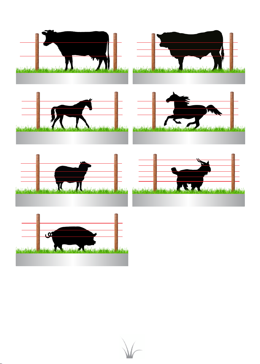
Dry ground is a poor conductor of electricity. In this circuit one adds an earth
return wire (B) to the fence. The animal now closes the circuit between the
live wire (A) and earth return wire (B) and so one does not rely on the poorly
conducve, dry ground to close the circuit.
Series wiring results in one long wire, thereby increasing the resistance of the
fence. This circuit is generally used for security fencing. Short out any wire and
the monitor will trigger an alarm.
DON’T
ØConnect more than one energizer to an earth stake
ØConnect your energizer earth to ESKOM or TELKOM’s earth stakes
ØAllow the earth system to touch any part of a building
ØConnect the earthing system to water pipes
ØInsert earth stakes where they can be tripped over
ØUse unlike metals e.g copper to galvanized, as this will cause electrolysis
Parallel
Wired
Fence Line
Resistance
of 2.24mm
H.S.S.
galvanized
wire is 40 Ω
per km.
Resistance of one Km of four strand fence wired in parallel will be:
1 1 1 1
4 1
+ + +
=
_ _ _ _
_
_ _
R R R R
40 10 = 10 Ω
Total R
so Total R
1=
Series
Wired
Fence Line
Resistance of one km of four strand fence wired in series will be:
R = R + R + R + R
R = (40 + 40 + 40 + 40)
R = 160 Ω
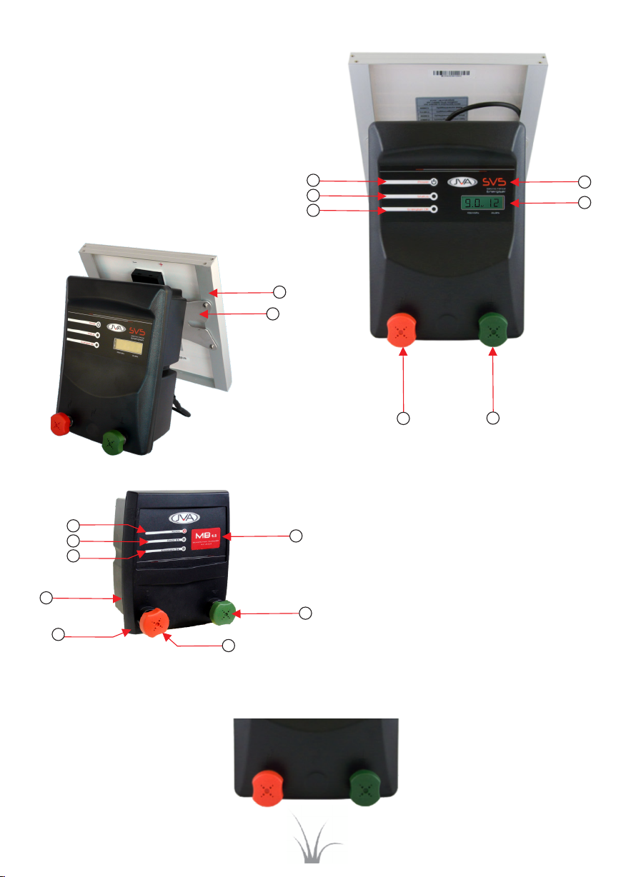
JVA Energizer
JVA Energizer
A
B