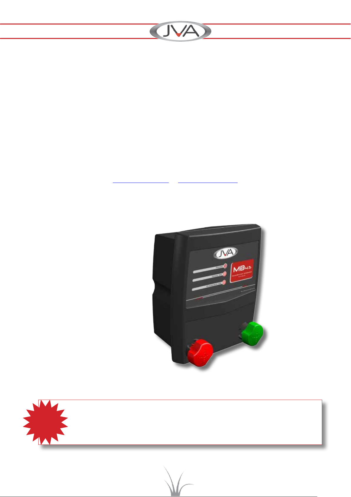
JVA MB1.5 User manual

JVA ELECTRIC FENCE ENERGIZER
MB1.5 • MB3.0 • MB4.5
Installation and User Manual
JVA AGRIRANGE ENERGIZERS
October 2019 Edition
www.jva-fence.com.au

MB1.5, MB3.0, MB4.5
ii
JVA AgriRange Energizers
INTRODUCTION
Congratulations, and welcome to the shocking world of JVA. We thank you for placing your faith in our
product range. In doing so you have joined the world-wide body of satised JVA users who are beneting
from our products.
The JVA range of energizers is the result of a joint venture between the Australian company, Pakton
Technologies and the South African company Ndlovu Fencing (Pty) Ltd. With over 40 years’ experience
in some of the harshest agricultural and security environments around the globe, JVA Technologies has
produced a comprehensive range of agricultural, wildlife and security energizers that meet the needs
of these diverse markets. The range extends from small strip grazing energizers to very high-powered
units which incorporate Wi-Fi, Auto-SyncTM, capable of partitioning long game fences into fty individual
sectors. For full particulars of our energizer ranges and fencing accessories, visit our websites:
www.jva-fence.com or www.jvasecurity.com
TWO-YEAR WARRANTY
All JVA products carry a 2-year warranty against defective components and faulty workmanship.
The warranty excludes damage caused by acts of Nature such as lightning, re and ooding,
power supply surges, rough handling, malicious action or incorrect wiring.
Consumable components (i.e. batteries) are also not covered under the warranty agreement.
2-yr
WARRANTY
MAINS OR BATTERY POWERED
(See warning on page 4)
ROBUST
AUTO-SYNCTM
EASY TO OPERATE
IEC/SANS 60335.2.76 APPROVED

MB1.5, MB3.0, MB4.5
iii
JVA AgriRange Energizers
Table of Contents
1. IMPORTANT NOTES – PLEASE READ .................................................. 1
1.1 Electric Fences............................................................................. 1
1.2 Energizers ................................................................................. 1
1.3 Power Supply Options ..................................................................... 1
1.4 Rechargeable Batteries ................................................................... 2
2. JVA MODELS AND FEATURES ........................................................... 2
2.1 Features ................................................................................... 2
2.2 Benets of Features........................................................................ 2
2.3 Specications .............................................................................. 3
3. PARTS OF THE ENERGIZER ............................................................. 4
3.1 Fence Connectors ......................................................................... 5
3.2 Energizer LED Display ..................................................................... 5
3.3 Power Button .............................................................................. 5
4. INSTALLATION............................................................................ 6
4.1 Location of the Energizer................................................................... 6
4.2 Mounting the Energizer .................................................................... 6
4.3 Connecting the Energizer to the Fence .................................................... 6
4.4 Powering the Energizer .................................................................... 6
5. OPERATION............................................................................... 7
5.1 Electric Fences............................................................................. 7
5.2 Benets of Electric Fences ................................................................. 7
5.3 All-Live Earth Return System............................................................... 8
5.4 Live-/Earth-Wire Fence Return System .................................................... 8
5.5 Earthing Your Energizer .................................................................... 9
5.6 Semi-Permanent and Permanent Fences .................................................. 9
5.7 The Importance of Insulators............................................................... 9
5.8 Maintenance ............................................................................... 9
6. COMMON ENERGIZER PROBLEMS ..................................................... 10
6.1 Flat Batteries............................................................................... 10
6.2 Lightning ................................................................................... 10
6.3 Moisture and Ants .......................................................................... 10
6.4 Blown Fuses ............................................................................... 10
6.5 Errors and Error Codes .................................................................... 11

MB1.5, MB3.0, MB4.5
iv
JVA AgriRange Energizers
7. COMMON FENCE PROBLEMS ........................................................... 11
7.1 Testing the Earthing System ............................................................... 11
7.2 Testing the Fence, Finding Shorts.......................................................... 11
8. INSTRUCTIONS FOR INSTALLATION AND CONNECTION OF ELECTRIC FENCES ... 12
8.1 Denitions.................................................................................. 12
8.2 General Requirements for Electric Fences ................................................. 12
9. WARRANTY ............................................................................... 14
9.1 For Assistance ............................................................................. 14
9.2 Service or Repairs ......................................................................... 14
9.3 Contacts ................................................................................... 14
Table of Contents (continued)
WARNING
Risk of shock!
►High voltages exist inside the electric fence energizer and on the fence terminals.
►High voltages are also retained for a while after switching o. It is advisable to wait for at least 10
minutes before opening the energizer case.
►Before working on the high voltage wiring of an electric fence, it is recommended that the energizer
be turned o and an intentional short circuit be placed from the fence live wires to earth. This is a
precaution against the energizer being turned on while work on the fence is in progress

MB1.5, MB3.0, MB4.5
1
JVA AgriRange Energizers
1. IMPORTANT NOTES – PLEASE READ
1.1 Electric Fences
1. Electric fences must be installed only in accordance with the relevant Standards and
Workplace Health and Safety regulations.
2. Electric fences are designed to deliver a short, safe shock. Do not let children play near them.
3. Electric fences must have warning signs. These must comply with IEC standards and should
be prominently displayed on electric fences at distances specied by the country in which
they are installed.
4. In order to operate eectively, electric fences must be well earthed. This involves the use of
galvanized, *steel stakes/spikes/rods/electrodes (various terms are in use) driven into the
earth at a depth of at least 1.2m. A minimum of 3 earth stakes are recommended at the
energizer. Additional earth stakes may be required on higher powered energizers and along
the fence in dry soil conditions. The deeper the earth stakes, the better.
* Hot-dipped galvanized steel earth stakes are recommended because the eectiveness
of the earthing is reduced by corrosion at the joints. This is caused by the electrolytic
eect resulting from a current owing through unlike metals making contact in a moist
environment.
1.2 Energizers
1. The energizer places a very short, safe, high voltage pulse on the fence live wires approximately
once every second. Please be advised that there is always a risk associated with any device
designed to impart an electric shock. Do not allow children or elderly persons to touch the
energizer or fence live wires.
2 The maximum length of fence able to be energized depends on many factors, for example the
earth resistance, competition from vegetation, number, spacing and conguration of wires –
series or parallel, type/quality of insulators, resistance of wire type used, etc. Another factor to
consider is acceptable fence voltage: for some livestock situations this is 3kV, others require
more or less. Therefore the rated mileage of fence that the energizer will power eectively is
a guide only.
3. WARNING! The energizer should never be operated with the cover removed as high voltages
exist inside the enclosure while operating. High voltage may remain on some internal parts
long after the unit has been switched o.
1.3 Power Supply Options
• 12V Battery (not supplied)
• 24V Battery (not supplied)
• 12V Battery with Solar panel (not supplied)
• 240Vac (via Power Pack) (13.8V DC Power Pack supplied)
The JVA MB1.5, MB3 and MB4.5 energizers have limited power supply options. For more
information please refer to section 2.2.

MB1.5, MB3.0, MB4.5
2
JVA AgriRange Energizers
N.B.
►Do not connect directly to mains – use the power supply provided.
►When using a battery option, always ensure adequate ventilation is given to the battery. Lead-
acid batteries may emit explosive gases while charging!
►Always mount the power supply either indoors or undercover.
1.4 Rechargeable Batteries
If powered from a rechargeable battery, JVA MB energizers are compatible with lead-acid batteries.
SLA battery life is shortened considerably if it is:
a) left in a discharged state or
b) exposed to very high temperatures.
WARNING!
SLA batteries can produce hydrogen. The energizer case is designed to release hydrogen gas to
prevent an explosion. Do not take steps to further seal the case. Return the unit for repair if the
O-ring seal has become damaged.
2. JVA MODELS AND FEATURES
2.1 Features
Table 1
Models Features
MB1.5, MB3.0, MB4.5 • Battery protection
• Solar capability
• Digital control
• Smooth wave shape
• Fence OK indicator
• Ant and moisture protection
• Lightning protection
• Power on demand
2.2 BenetsofFeatures
►The battery life maximization works by slowing the frequency of high voltage pulses
just before the battery dies to keep the energizer operating for as long as possible without
damaging the battery.
►The over discharge battery protection will stop the energizer when the battery is at and
ash the status LED twice each second. This stops too much charge being extracted from the
battery and prevents permanent damage. The energizer will restart automatically once the
battery voltage returns to a normal level.
►The reverse battery protection protects the energizer from damage should the external
battery be connected the wrong way round in error.

MB1.5, MB3.0, MB4.5
3
JVA AgriRange Energizers
►The MB series of energizers has the electronics enclosed inside a durable UV stable case
to protect against ants, moisture and dust and so maximize reliability.
►The overload indication warns if the fence is heavily loaded by ashing a warning LED and
alerting with a short audible beep.
►The MB series utilizes the latest digital microcontroller technology to extend battery life,
provide useful feedback on the energizer status, and increase reliability and performance.
►The audible alarm will sound in the event of a serious error for 30 seconds and then shut
down for 7 minutes before sounding again.
►The Auto Recover feature will attempt to recover the energizer from severe errors which
cause the energizer to stop working. This automatic recovery process will occur at 7-minute
intervals.
►Power on demand automatically increases the power to heavy fence loads.
►To use the MB Range with a solar panel, an external 12 volt sealed lead-acid battery, solar
panel and solar regulator are required.
2.3 Specications
Table 2
Specications
Model
*a
Energizer
output
voltage
Stored
Energy Power *d 12V
drain
*c Solar Panel Size for Minimum
Expected Sun Hours Per Day *c Solar
Battery
Peak
Output
3hrs 4hrs 5hrs >6hrs
MB1.5 8.2kV 2.1J *b 12Vdc 165mA 30W 20W 20W 15W
26Ah
1.5J
MB3 8.5kV 4.2J *b 12Vdc
300mA 40W 30W 25W 20W
40Ah 3.0J
MB4.5 8.8kV 6.3J *b 12Vdc
490mA 85W 60W 40W 40W
65Ah 4.5J
KEY
*a No load, actual voltage on a short fence can be as high as 10kV
*b The energizer can also be powered from 240Vac by using the external power pack supplied with
the energizer.
*c Minimum recommended sizes for 5 consecutive days of overcast weather.
*d Current drain rating is for a 12V power source. Current drain will vary with voltage.
In line with our policy of continual improvement, specications are subject to change without notice.

MB1.5, MB3.0, MB4.5
4
JVA AgriRange Energizers
1
3
2
4
5
7
6
8
1. On/O switch (not on MB1.5 and MB3)
2. Fence OK indicator (red LED)
3. Energizer On and OK indicator (green LED)
4. Rubber O-ring seal between front and back case pieces
5. Power cable extends from base of case
6. Fence connection terminal
7. Earth connection terminal
8. Model number
3. PARTS OF THE ENERGIZER
MB1.5, MB3.0, MB4.5
WARNING: Do not connect the energizer directly to mains. Use the 12VDC power supply provided.

MB1.5, MB3.0, MB4.5
5
JVA AgriRange Energizers
3.1 Fence Connectors
Fence terminal Earth terminal
Fence terminal – should be connected to the live wires of the fence.
Earth terminal – should be connected to a suitable electric fence earth stake.
3.2 Energizer LED Display
This feature is included in all units.
Fence OK LED
Energizer OK LED
Fence OK red LED – Flashes if fence voltage is good. If it goes o there is a problem on the fence.
Energizer OK green LED – Flashes with each pulse to show the unit is on and operating correctly.
3.3 Power Button
The power button turns the energizer on or o, and silences the beeper.
• If the energizer is o, push the Power button to turn it on.
• If the beeper is giving an audible warning, push the Power button to silence the beeper for 10
minutes.
• If the energizer is on, push the Power button to turn it o.

MB1.5, MB3.0, MB4.5
6
JVA AgriRange Energizers
4. INSTALLATION
4.1 Location of the Energizer
If possible keep the energizer in a cool and dry environment (either indoors or at least well
covered) to maximize reliability. To deter any water ingress, keep the energizer upright when
located outdoors.
41 Mounting the Energizer
There are a number of mounting options.
• Wall Mount: The energizer may be mounted from two screws
• Shelf Mount: Lay or stand the energizer on a shelf
• Hang Mount: Thread wire or string through the keyholes to hang the energizer, or hang the
energizer from a single nail or hook.
4.2 Connecting the Energizer to the Fence
• The electric fence requires a dedicated ground/earth system. Drive at least three galvanized
earth stakes into the ground to a depth of at least 1.2m. Attach a wire from the green Earth
Terminal connector on the front of the energizer to the earth stake.
• Connect a wire from the red Fence Terminal connector the front of the energizer to the live
wire of the fence.
4.3 Powering the Energizer
Mains Power Source (MB1.5, MB3.0 and MB4.5): Plug the power adapter (MB1.5, MB3.0 and
MB4.5) supplied with the energizer, into an AC power source and the energizer.
Turn the energizer ON by pressing the On/O switch.
Battery Power Source (1.5, MB3): Attach the battery, red to positive and black to negative
battery terminals. For battery choice see specication Table 2 on page 3. Turn the energizer ON
by pressing the On/O switch.

MB1.5, MB3.0, MB4.5
7
JVA AgriRange Energizers
5. OPERATION
5.1 Electric Fences
Electric fence energizers work by discharging a short, safe, high voltage pulse onto the fence
wires. The animal will not be harmed by a pulse, but it will remember to avoid contact with the
energized fence in future.
The high voltage is discharged from the red, positive fence terminal of the energizer and this is
connected to the fence wire or electric fence tape to make them live or ‘hot’ wires. Live wires must
be insulated from earth or any conductive material touching the ground, e.g. fence posts).
The green Terminal connector on the energizer is the earth (or ground) terminal. Electric fences
need earthing to complete the circuit: When an animal touches the live wire of the fence, a current
will ow from the live wire, through the animal, back through the ground or the earth return wires
to the earth stake and back up to the energizer earth terminal thereby completing the circuit. (See
Fig 1 below)
On touching the earth terminal on the energizer or the earth stakes in the ground, no shock should
be felt. If a shock is felt on either of the above, it is an indication that the earthing is insucient. To
overcome this problem, extra earth stakes need to be added to the system. The better the quality
of the earthing system, the more eective and ecient the electric fence system will be.
The more earth stakes in the ground and the higher the moisture content in the soil, the better
the system will function. The higher powered (higher joule rating) the energizer and the longer the
fence, the more earthing is required.
In very dry conditions and sandy soils, it is recommended that a dedicated earth wire be added
to the fence line. This in turn should be connected to the energizer earth and the ground/earth
stakes. (See Fig 2)
For best results locate the energizer as centrally as possible in a fencing layout.
The fence and the earth voltages can be measured using an electric fence digital voltmeter, or a
digital electric fence directional fault nder, such as the JVA Electric Fence Digital Directional Fault
Finder.
5.2 BenetsofElectricFences
► An electric fence oers a psychological barrier as well as a physical barrier.
►The risk of injury to livestock is lower than with barbed wire fences.
►Electric fences cost less to install and maintain than conventional fencing. Users enjoy low
maintenance costs because their stock stays o the fence.
►Their use is versatile:
– they can be permanent or portable systems
– they can be arranged in variety of designs to suit needs
– they are quick and easy to erect
►They improve pasture and grazing control
►They can improve existing fence life as a result of less physical pressure on the fence
►They are easy to set up compared with traditional fences.

MB1.5, MB3.0, MB4.5
8
JVA AgriRange Energizers
5.3 All-Live Wire, Earth Return System
The Earth Return (also called Ground Return) conguration is the most common method of
conguration for electric fences, particularly smaller fence applications like strip grazing. The
fence live wire(s) are electried and rely on the soil to complete the circuit back to the energizer
Earth Terminal when an animal touches the fence.
The electrical circuit
is closed between
the fence and the ground
when the animal touches the fence
The circuit is closed
when the animal nudges
both the live and Earth wires
of a fence
A good circuit requires adequate current ow through
the ground (through moist soil)
5.4 Live-/Earth-Wire Fence Return System
The live-/earth-wire fence return conguration for electric fences is used where the soil is too dry to
complete the circuit adequately, or the animals are likely to try to force their way through between
the fence wires. In this system earth wire(s) are also run along the fence with the live wire(s) to
provide a low resistance path for the current to return to the energizer. In this system if the soil is
moist enough it will also function as a return path for the current when the animal touches the live
wire, but if the soil is not moist or has poor conductance, this system will keep your fence eective
provided the animal touches both a live and the earth wire simultaneously.
Fig 1
Fig 2
The earthed fence wire provides the current ow required
to complete the circuit when the ground cannot
Earth
Stake
Earth
Stake

MB1.5, MB3.0, MB4.5
9
JVA AgriRange Energizers
5.5 Earthing Your Energizer
The best way to earth an energizer is to use a minimum of 1.2 metre galvanized earth stakes.
If the earth stake is too rusty it will not work properly. The best place to locate the earth stake is
somewhere close to where the fence commences and if possible where the ground is damp such
as a garden bed, a water course, or the overow from a rain water tank. (South African regulations
require a minimum of 3 earth stakes to be located close to the energizer.) Do not connect the earth
of the energizer to a metal shed, metal pipes or utility earthing system as this could lead to shock
from tap, showers etc.
5.6 Semi-Permanent and Permanent Fences
The quickest and easiest way to set up a permanent fence is to use steel posts, but timber and
berglass posts can also be used. Make sure that the wires are tight enough to eliminate sagging.
2.5mm galvanized fence wire is recommended as poly tape or rope will degrade and break over
time. Warning signs need to be tted as per the requirements outlined in the, General Requirements
for Electric Fences section of this manual.
5.7 The Importance of Insulators
If the live wire is not well insulated the fence load will be much higher. This means that, for any
given length of fence, the voltage will be lower. Pieces of wood and garden hose are not good
insulators! For reliable results standard insulators designed for this purpose are recommended.
In a live-/earth-wire fence return system the earth wire(s) do not need to be insulated. In fact,
if using steel intermediates, the more times the earth wire touches a metal post the better it is
earthed/grounded.
UV stable poly insulators will last much longer than non-UV stable plastics. Plastic insulators are
not as susceptible to fracture as ceramic insulators. However, ceramic insulators are better in
grass, re prone areas as they do not melt.
5.8 Maintenance
Maintaining permanent fences is important, especially during the warmer months when plant
growth is at its highest and after any disruptive weather events.
1. Check the fence voltage using an electric fence voltmeter. The JVA Fault Finder will also
detect faults and direct you towards them.
2. Keep vegetation away from the fence. If it touches the fence it will reduce its performance.
The judicious use of weed killer may be used if so wished to deter any growth.
3. Check that nothing has fallen against the fence and that the wires are not broken or have
been unclipped from insulators.
4. Check the condition of the earthing system for corrosion and loose joints.
5. Check that lightning diverters are all still operational.
6. Check and tighten any loose line clamps along the fence.
7. Check the energizer battery. If the energizer is ashing a low battery warning it is time to
recharge or replace the battery.

MB1.5, MB3.0, MB4.5
10
JVA AgriRange Energizers
6. COMMON ENERGIZER PROBLEMS
The most common problems with electric fence energizers are:
• Flat batteries
• Lightning
• Moisture and ants
• Blown fuses
The intelligent JVA Series of energizers will self-diagnose and report their status. (See Errors and
Error Codes) on the LED and LCD displays.
6.1 Flat Batteries
The JVA series energizers, to run eectively, require a battery that is in good condition. The
energizer will protect the battery by slowing down and eventually stopping altogether as the battery
charge is depleted. For best results, check on the energizer at regular intervals. If not receiving the
expected life from a battery consider having it checked by an electrician.
6.2 Lightning
The JVA range of energizers is covered with a two-year warranty that excludes lightning. Surge
protection components inside the energizer are tted to reduce the risk of damage by lightning.
However, nature is capable of performing more extremely than can be tested for in the laboratory;
to ensure the wellbeing of your JVA investment for the long term, it is recommended that a Lightning
Protection Kit is installed to prevent lightning damage and possible costly repairs.
6.3 Moisture and Ants
Moisture and ants should not be a signicant problem for the JVA range of energizers as they are
protected in a weatherproof case. However, where possible, keep the energizer protected from
the weather.
6.4 Blown Fuses
The fuse used is a self-resetting type. Disconnect the power for a minute and then reapply the
power. If the unit still does not power up, return it to a service centre.

MB1.5, MB3.0, MB4.5
11
JVA AgriRange Energizers
6.5 Errors and Error Codes
The JVA energizer may stop and display error codes. The error codes are displayed in two places.
The rst of these is on the Status (red) LED, where it will ash rapidly a number of times. The
number of these ashes corresponds to the Error Code. The second place is on the LCD, where
it will display a message.
Table 3
Error
Code #
Red LED
Flashes LCD Display Meaning
2 2 Battery symbol
“Lo b”
Flat Battery: the energizer will recover and re-start when
the battery is recharged.
6 6 “Er 06” High battery: the energizer will re- start when the
battery voltage is returned to the correct range
Errors 2 and 6 indicate the battery voltage is either too low or too high. The energizer will restart as
soon as the voltage returns to the correct range. All other errors indicate an internal malfunction.
Should the error continue to re-occur, please return the unit to a qualied service centre for repair.
There are no user-serviceable parts inside the energizer. All internal fuses will automatically reset
themselves.
7. COMMON FENCE PROBLEMS
The most common problem with electric fences is low voltage on the live wires caused by
• Inadequate earthing/grounding
• Shorts on the fence
For tips on fence construction please refer to an Electric Fencing Manual.
7.1 Testing the Earthing/Grounding System
The earth/ground is essential to all electric fence systems. Larger energizers require more earth
spikes/stakes/rods/electrodes.Additionally, all energizers require a low resistance wired connection
from the energizer earth terminal to the earth stake.
Short the end of your fence to earth by hammering a metal stake into the soil and connecting
this to the live fence wire. Using an electric fence voltmeter or a JVA Electric Fence Fault Finder,
(Do not use a standard multimeter.) check the voltage is at the earth terminal of the energizer. In
general it should be a reading less than 300 volts (0.3kV).
7.2 Testing the Fence, Finding Shorts
To test the performance of the fence or nd faults on the fence, an electric fence voltmeter is
essential, and a JVA Electric Fence Fault Finder is even better. An eective fence will have more
than 2 kV (2000 volts).

MB1.5, MB3.0, MB4.5
12
JVA AgriRange Energizers
8. INSTRUCTIONS FOR THE INSTALLATION AND
CONNECTION OF ELECTRIC FENCES
Instructions for installation and connection of electric fences vary from country to country. Most are
based on the International Electrical Commission (IEC) AS60335.2.76 specications.
This material is copyright of the International Electrical Commission (IEC).
8.1 Denitions
Connecting lead an electric conductor, used to connect the energizer to the electric fence
or the earth electrode (stake)
Electric animal fence an electric fence used to contain animals within or exclude animals from
a particular area
Electric fence a barrier which includes one or more electric conductors, insulated from
earth, to which electric pulses are applied by an energizer
8.2 General Requirements for Electric Fences
1. Electric animal fences shall be installed and operated so that they cause no electrical hazard
to persons, animals or their surroundings.
2. Electric animal fence constructions which are likely to lead to the entanglement of animals or
persons shall be avoided.
3. An electric animal fence shall not be supplied from two dierent energizers or from independent
fence circuits of the same energizer. For any two separate electric animal fences, each
supplied from a separate energizer independently timed, the distance between the wires of
the two electric animal fences shall be at least 2 m. If this gap is to be closed, this shall be
eected by means of electrically non-conductive material or an isolated metal barrier.
4. Barbed wire or razor wire shall not be electried by an energizer.
5. Any part of an electric animal fence that is installed along a public road or pathway shall be
identied at frequent intervals by warning signs securely fastened to the fence posts or rmly
clamped to the fence wires.
a) The size of the warning sign shall be at least 100 mm ×200 mm.
b) The background colour of both sides of the warning
sign shall be yellow. The inscription on the sign shall
be black and shall be either:
• the symbol of Figure 3, or
• the substance of TAKE CARE – ELECTRIC
ANIMAL FENCE
c) The inscription shall be indelible, inscribed on both
sides of the warning sign and have a height of at
least 25 mm. Figure 3 – Warning plate symbol

MB1.5, MB3.0, MB4.5
13
JVA AgriRange Energizers
6. The energizer earth electrode shall penetrate the ground to a depth of at least 1.2 m.
7. Connecting leads that are run inside buildings shall be eectively insulated from the earthed
structural parts of the building. This may be achieved by using insulated high voltage cable.
8. Connecting leads that are run underground shall be run in a conduit of insulating material
or else insulated high voltage cable shall be used. Care must be taken to avoid damage to
the connecting leads due to the eects of animal hooves or tractor wheels sinking into the
ground.
9. Connecting leads shall not be installed in the same conduit as the mains supply wiring,
communicating cables or data cables.
10. Connecting leads and electric animal fence wires shall not cross above overhead power
or communication lines.
11. Crossings with overhead power lines shall be avoided wherever possible. If such a crossing
cannot be avoided, it shall be made underneath the power line and as nearly as possible at
right angles to it.
12. If connecting leads and electric animal fence wires are installed near an overhead power
line, the clearances shall be not less than those shown in table 5 below.
Table 4
Power line voltage V Clearance m
<=1 000 3
>1 000 <=33 000 4
>33 000 8
Minimum Clearances from Power Lines
13. If connecting leads and electric animal fence wires are installed near an overhead power
line, their height above the ground shall not exceed 3m. This height applies either side of the
orthogonal projection of the outermost conductors of the power line on the ground surface,
for a distance of
• 2 m for power lines operating at a nominal voltage not exceeding 1,000 V
• 15 m for power lines operating at a nominal voltage exceeding 1,000 V.

MB1.5, MB3.0, MB4.5
14
JVA AgriRange Energizers
9. WARRANTY
This material is copyright of the International Electrical Commission (IEC).
9.1 For Assistance
If you have any questions or need further assistance, or for more information on our complete
range of electric fencing products, please see the JVA website at www.jva-fence.com.
9.2 Service or Repairs
If service is required, package your energizer carefully and return it to the place of purchase or
your nearest JVA distributor along with your proof of purchase.
9.3 Contacts
www.jva-fence.com.au
www.jva.security.co.za
www.jva-fence.com
Manufactured for JVA by Pakton Technologies
The JVA logo is a trademark of JVA Technologies Pty Ltd
ST058 JVA MM Energizer Manual 1v31

MB1.5, MB3.0, MB4.5
15
JVA AgriRange Energizers
The JVA range of agricultural and security electric fence energizers are the result of a
joint venture between the Australian company, Pakton Technologies and South African
company, Ndlovu Fencing (Pty) Ltd. With a combined experience of well over 40 years
in the industry, and drawing on experiences from operating in some of the hardest
agricultural and security environments around the globe, JVA produce a comprehensive
range of both agricultural and security energizers that meet the needs of both markets.
For full particulars of our ranges of energizers and accessories visit:
The JVA range of agricultural and security electric fence energizers are the result
of a joint venture between the Australian company, Pakton Technologies and
South African company, Ndlovu Fencing (Pty) Ltd. With a combined experience of
well over 40 years in the industry, and drawing on experiences from operang in
some of the hardest agricultural and security environments around the globe, JVA
produce a comprehensive range of both agricultural and security energizers that
meet the needs of both markets. For full parculars of our ranges of energizers
and accessories visit:
www.jva-fence.com www.jvasecurity.com
www.jva-fence.com
AUSTRALIA AFRICA NEW ZEALAND
LATINO
AMERICA CARIBBEAN SOUTH EAST ASIA
EUROPE
BRAZIL
RUSSIA INDIA
USA MEXICO
MALAYSIA CENTRAL ASIA UNITED KINGDOM
PAKISTAN PANAMA PHILIPPINES
www.jvasecurity.comwww.jva-fence.com
JVA AGRIRANGE ENERGIZERS
The JVA range of agricultural and security electric fence energizers are the result
of a joint venture between the Australian company, Pakton Technologies and
South African company, Ndlovu Fencing (Pty) Ltd. With a combined experience of
well over 40 years in the industry, and drawing on experiences from operang in
some of the hardest agricultural and security environments around the globe, JVA
produce a comprehensive range of both agricultural and security energizers that
meet the needs of both markets. For full parculars of our ranges of energizers
and accessories visit:
www.jva-fence.com www.jvasecurity.com
www.jva-fence.com
AUSTRALIA AFRICA NEW ZEALAND
LATINO
AMERICA CARIBBEAN SOUTH EAST ASIA
EUROPE
BRAZIL
RUSSIA INDIA
USA MEXICO
MALAYSIA CENTRAL ASIA UNITED KINGDOM
PAKISTAN PANAMA PHILIPPINES
This manual suits for next models
2
Table of contents
Other JVA Power Supply manuals