Page 10 © JVA Technologies Pty. Ltd.
Quick Start Guide
JVA Z28 Manual
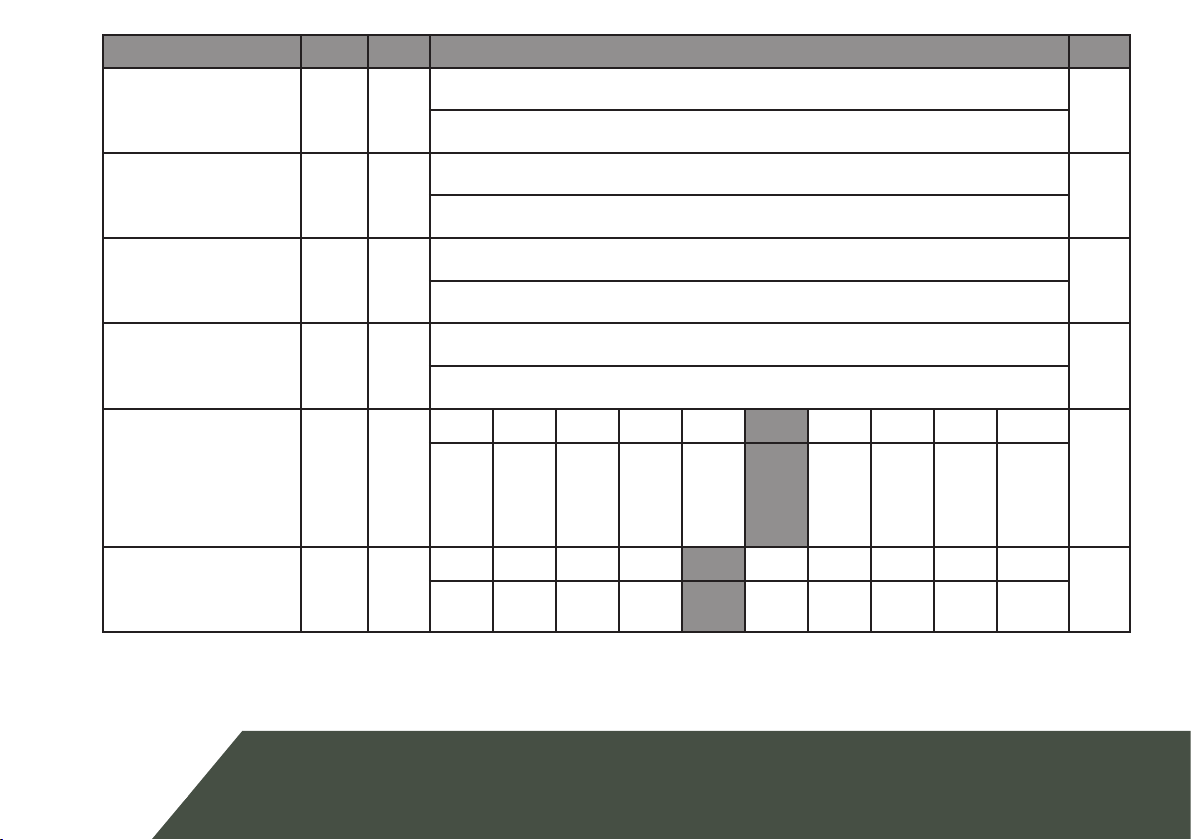
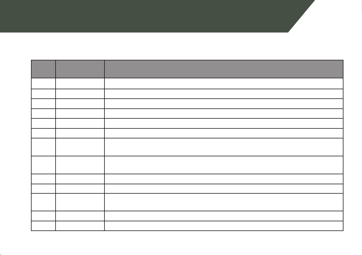
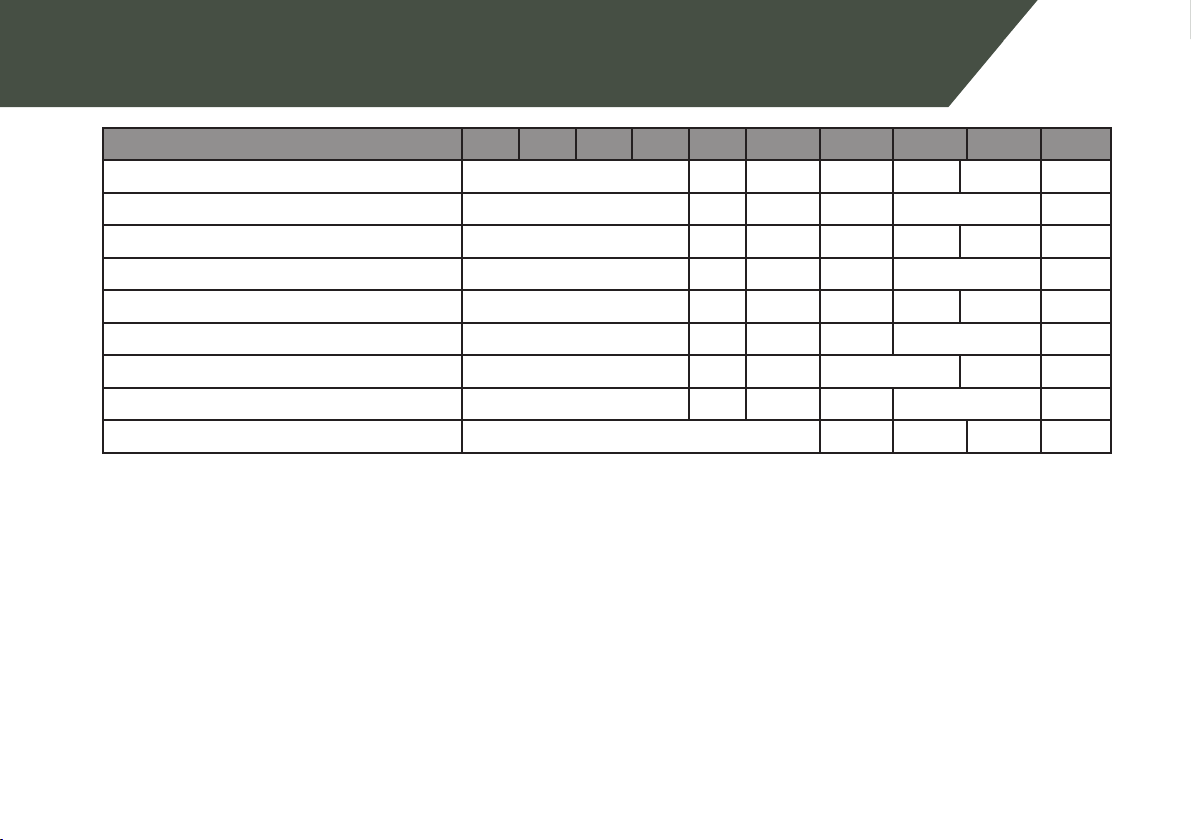
1.1.1 Relay Funcons
The table below is for use for the relay programming opons menoned in the table on the previous page.
Keys 3
and 4
Funcon Descripon
00 Fence 1 Triggers when Zone 1 is Armed and Return Voltage is below the Threshold Voltage
01 Fence 1 or O Triggers when Zone 1 is Disarmed or Return Voltage is below the Threshold Voltage
02 Armed 1 Zone 1 is Armed
03 Fence 2 Triggers when Zone 2 is Armed and Return Voltage is below the Threshold Voltage
04 Fence 2 or O Triggers when Zone 2 is Disarmed or Return Voltage is below the Threshold Voltage
05 Armed 2 Zone 2 is Armed
07 General Triggers on AC Fail, Tamper, Low Baery/Bad Baery, Gate Alarm or Internal error.
Latched (internal errors only)
08 Siren Triggers on Fence Alarm, Gate or Tamper. Will me out aer the Siren Time Out me.
Latched
09 Strobe Triggers on Fence alarm, Gate or Tamper. Only turns o on Energizer Disarm. Latched
10 AC Fail Triggers on AC Fail
11 Low/Bad Bat-
tery
Triggers on Low or Bad Baery
12 Tamper Triggers when the Tamper Input (if congured) is triggered
14 Gate 1 or 2 Triggers on a Gate Alarm