JVA Z28 User manual

SECURITY
ENERGIZER
Installation and User Manual
28
JVA ELECTRIC FENCE SYSTEMS
Edition 2.3, July 2019

JVA Z Energizer Range Concept
Thank you for choosing our product. The JVA brand is a range of electric fencing
products carefully selected from leading manufacturers around the world to
meet the needs of perimeter security.
THE JVA Z RANGE ENERGIZER CONCEPT
The JVA Range of Energizers has been collaboratively designed and manufactured
by an international team with over 30 years of electric fence experience earned
in some of the most testing security environments in the world. It aims to provide
the very best low-cost, high-voltage security energizers in the world. They are
compact, integrated and fully programmable electric fence energizers with built-in
alarm units and LCD out and return voltage display. They also have the option of
being controlled from a remote LCD keypad.
State-of-the-
art energizer
design IP4 x
and ABS plastic
Unique LCD
display depicting
fence out and
return voltage
Wall-mountable, robust
energizer housing with easily
detachable PCB chassis for
ease of installation and repair
Unique LCD keypad
option depicting fence
and alarm condition
TWO-YEAR WARRANTY
All JVA products carry a 2-year warranty against defective
components and workmanship. The warranty excludes damage
caused by acts of Nature such as lightning or ooding, power
supply surges, rough handling, malicious action or incorrect wiring.
Please retain your invoice as proof of purchase and
ll in the warranty form on page 39.
2-yr
WARRANTY
JVA ELECTRIC FENCE SYSTEMS

1
JVA ELECTRIC FENCE SYSTEMS JVA ELECTRIC FENCE SYSTEMS
Contents
1. INTRODUCTION ...................................................................................... 3
2. FEATURES ............................................................................................... 4
2.1 Power .............................................................................................. 4
2.2 Control / Monitoring ......................................................................... 4
2.3 Safety .............................................................................................. 4
2.4 Reliability ......................................................................................... 4
3. SPECIFICATIONS .................................................................................... 5
4. DESCRIPTION ......................................................................................... 6
4.1 JVA Z28 Exterior .............................................................................. 6
4.2 JVA Z28 – High Voltage Terminals .................................................. 6
4.3 LCD Voltage Display ........................................................................ 7
4.4 Status LED Lights ............................................................................ 8
4.5 Inputs and Outputs .......................................................................... 8
4.5.1 Relay Functions ................................................................... 9
4.6 4-line LCD Keypad .......................................................................... 10
4.7 Internal Beeper / Keypad Beeper .................................................... 22
4.8 Cabling ............................................................................................ 22
4.9 Lightning Protection ......................................................................... 22
4.10 Earth Loop Monitoring ..................................................................... 22
4.11 Noise and Interference .................................................................... 22
4.12 Programmable Options .................................................................... 22
4.13 Low Power Mode ............................................................................. 22
4.14 Control Inputs .................................................................................. 23
4.14.1 Control Inputs ...................................................................... 23
4.14.2 Control Input Functions ....................................................... 23
4.14.3 Keyswitch Inputs .................................................................. 23
4.15 Simultaneous Pulse Feature ........................................................... 23
5. INSTALLATION ......................................................................................... 24
JVA recommends installation by qualied technicians
5.1 Installation Steps ............................................................................. 24
5.2 Example Fence Wiring Diagrams .................................................... 25
CONTENTS

JVA ELECTRIC FENCE SYSTEMS JVA ELECTRIC FENCE SYSTEMS
2
JVA ELECTRIC FENCE SYSTEMS JVA ELECTRIC FENCE SYSTEMS
Contents
6. OPERATION ............................................................................................. 27
6.1 Arm / Disarm Control ....................................................................... 27
6.2 Arming the Fence Using the Keypad ............................................... 27
6.3 Turning to Low Power Mode ............................................................ 27
6.4 When an Alarm Occurs .................................................................... 27
6.5 To Silence the Alarm ........................................................................ 28
6.6 Changing the PIN number ............................................................... 28
6.7 Standby Battery ............................................................................... 28
6.8 Status Light ...................................................................................... 28
7. TECHNICAL INFORMATION .................................................................... 29
8.1 Power Options ................................................................................. 29
8.2 Status Codes ................................................................................... 30
8.3 Jumpers ........................................................................................... 30
8.3 Multiple Keypads ............................................................................. 30
8. GROUP MODE ......................................................................................... 31
9. SECTOR SETUP TESTS AND ADJUSTMENT ........................................ 34
9.1 Basic Fence Tests ........................................................................... 34
9.2 Fault Condition Tests ...................................................................... 34
10. SOME STANDARD REQUIREMENTS FOR ELECTRIC
SECURITY FENCES ................................................................................ 35
........................................................................................ 35
10.2 Installation, Operation and Maintenance ......................................... 35
10.3 Warning signs .................................................................................. 36
10.4 Gates ............................................................................................... 36
10.5 Earthing ........................................................................................... 36
10.6 Protection ........................................................................................ 37
11. WARRANTY ............................................................................................. 39
12. COMPLIANCE CERTIFICATE .................................................................. 40

3
JVA ELECTRIC FENCE SYSTEMS JVA ELECTRIC FENCE SYSTEMS
Introduction
JVA ELECTRIC FENCE SYSTEMS JVA ELECTRIC FENCE SYSTEMS
1. INTRODUCTION
Welcome to the world of JVA monitored electric security fences. The proliferation of
non-lethal, monitored, electric security fences in our towns and cities is indicative of
system:
D – The JVA fence around your property shows you mean business.
D
D – The safe, powerful JVA shock is a strong deterrent to intruders.
D – The physical barrier will delay an intruder, something they do not like.
D
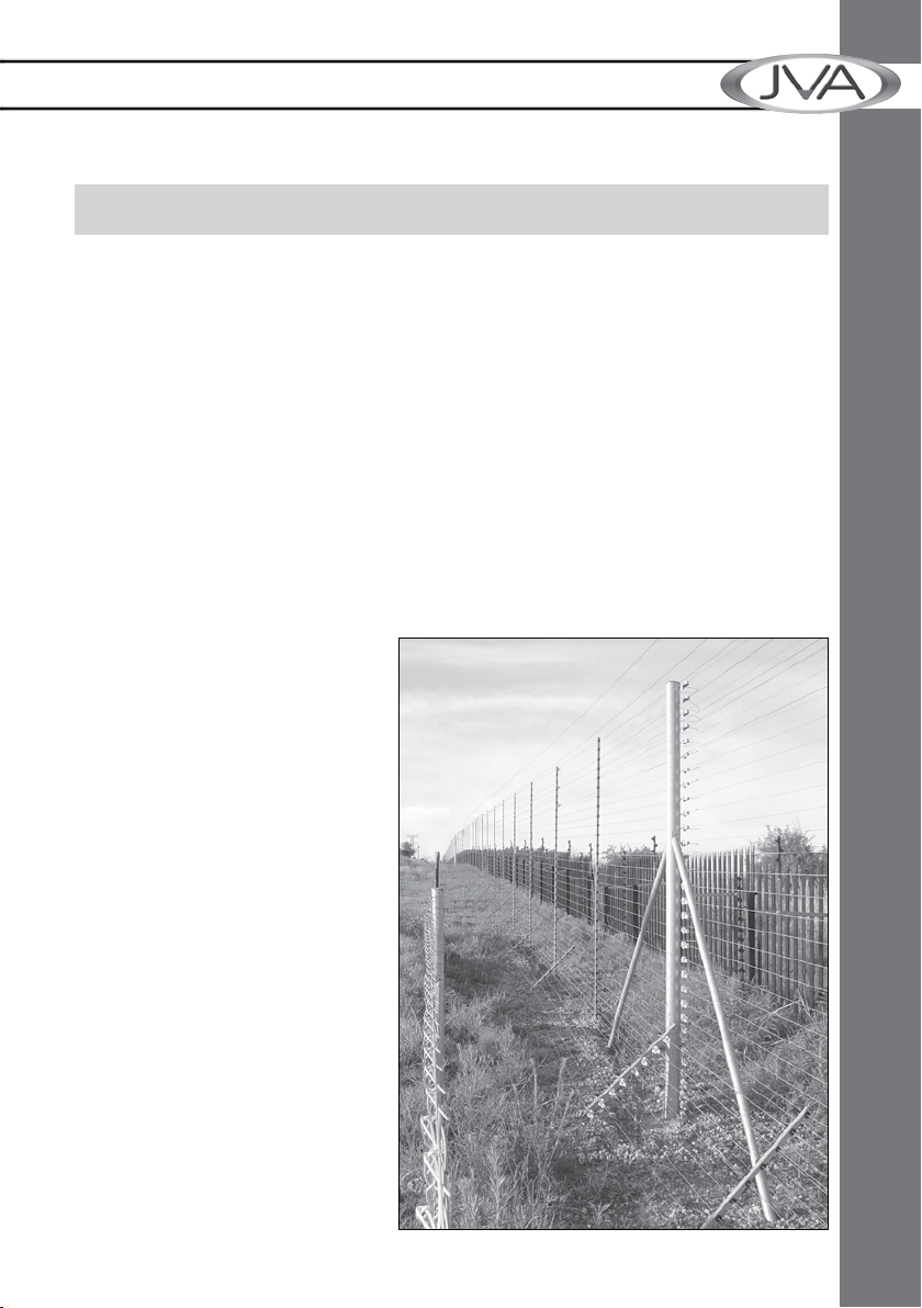
D – A well-erected electric security fence will deny entry.
D – 60 seconds a minute, 60 minutes an hour, 24 hours a day, 365 days
a year, your JVA electric security fence is monitored by an alert, sober, electronic
watchman.
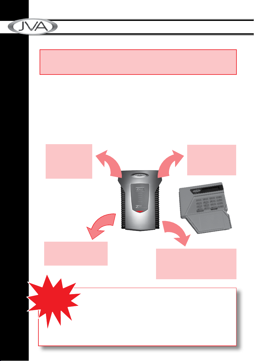
Every second, the JVA Z energizer
discharges a very short-duration,
safe, high-voltage pulse down
the fence live wire. The JVA Z
energizer then monitors the voltage
at the end of this live wire, thereby
checking that the voltage is being
maintained along the entire fence
line. In the event of a voltage drop
caused by either shorting, cutting
or poor maintenance, the monitor
will trigger an alarm, thus alerting
you.
Manufactured to meet the most
stringent international safety
standards, the JVA Z energizer is
in a class of its own when it comes
An electric fence system which
meets current safety regulations

JVA ELECTRIC FENCE SYSTEMS JVA ELECTRIC FENCE SYSTEMS
4
JVA ELECTRIC FENCE SYSTEMS JVA ELECTRIC FENCE SYSTEMS
Features
2. FEATURES
2.1 Power
8 joules peak output energy (4 + 4 Joules = 8 Joules total)
Mains powered via external transformer (16–18Vac)
Battery charger with space for internal 7A/H 12V rechargeable back up battery
NOTE: A 9 A/h battery may be used as it is the same size as a 7 A/h battery
2.2 Control / Monitoring
3 12V driven outputs (also referred to as relays), high side switched (common
negative)
All relays may be assigned to any alarm function
LCD voltage display
LED status lights
Internal beeper
AC fail, Low Battery and Bad Battery detection
Keypad programmable options
Low power mode – ensures detection together with public safety during the day
Adjustable energizer power output level
2.3 Safety
Designed to pass IEC60335.2.76 and EMC standards (reports available on
request)
Enclosed fence terminals
Wall mountable, robust enclosure with detachable PCB chassis for ease of
installation and repair
2.4 Reliability
Microprocessor controlled.
Pluggable screw terminals
State of the art, robust, case design IP4x ABS
Built-in lightning protection from both mains and fence sides, external fence
lightning protection is still advised in high lightning prone areas
All inputs and outputs protected against stray fence voltage

5
JVA ELECTRIC FENCE SYSTEMS JVA ELECTRIC FENCE SYSTEMS
Specications
JVA ELECTRIC FENCE SYSTEMS JVA ELECTRIC FENCE SYSTEMS
3. SPECIFICATIONS
Specication Name Specication
Energizer Output Voltage 8.5kV peak no load
Peak Output Energy 2 ×4 Joules
Pulse Rate Locked at 0.9 Hz
12v DC Power Consumption Energizer On – 1005mA average, 1220mA peak
Not including keypad or Auxiliary power
AC Power Input 16-18Vac 1.5A*
Battery Charger Output Float voltage 14V, 700mA, short circuit
protection, reverse battery protection
Switched Outputs Three 12V 2.5A maximum combined load
powered output.
Recommended Operating
Temperature
–15°C to +50°C
Enclosure IP4x ABS Plastic
Size 300mm high, 190mm wide, 115mm deep
Weight – packed, no battery 2.5kg
Series energizers.
take a long time to discharge. Wait at least 10 minutes
-
mended that the energizer be disarmed and an intentional short circuit
is placed from the fence live wires to earth. This is a sensible precaution
against the energizer being turned on by others or malfunctioning while
working on the fence.
between two separate electric fences, each powered by separate energiz-
group mode.
WARNING
* A 24Vdc 1.5A supply can be used in place of the 16Vac. The correct connection is +24V to the right AC
pin, GND to the left AC pin. Due to the stored energy in a 24Vdc plug-pack, an AC Fail could occur 5
minutes before the Energizer reports this fault

6
JVA ELECTRIC FENCE SYSTEMS JVA ELECTRIC FENCE SYSTEMS
Description
4. DESCRIPTION
4.1 JVA Z28 Exterior
4.2 JVA Z28 – High Voltage Terminals
Figure 1: Z28
Figure 2: Output Terminals
ZONE 1 OUT
EARTH
ZONE 2 OUT
ZONE 1 RETURN
EARTH RETURN
ZONE 2 RETURN
The Z28 is a dual channel standard (non Bi-Polar) 8 Joule (4 per channel) security
energizer.
This manual relates to:
the LCD on reset)
9.2 9.0

7
JVA ELECTRIC FENCE SYSTEMS JVA ELECTRIC FENCE SYSTEMS
Description
4.3 LCD Voltage Display
The display on the JVA Z28 shows the voltage at the feed out and return terminals.
Left side = Return zone 1, Right side = Return zone 2.
The Stored Joules will be displayed every approximately 4–5 seconds. The reading
will vary depending on the load on the fence. Stored Joules displayed is the current
stored joules to generate the output voltage as programmed. If the fence is in good
condition, this value will be low. As more load comes onto the fence, the amount of
joules will increase to meet the requested voltage.
The LCD also shows the programming option and current setting when in
programming mode. This allows the programming options settings to be checked
easily.
Figure 3: LCD Display and Status LEDs
ZONE 1 – RETURN HV – ZONE 2

8
JVA ELECTRIC FENCE SYSTEMS JVA ELECTRIC FENCE SYSTEMS
Description
4.5 Inputs and Outputs
Figure 4: Connection Terminals
4.4 Status Lights
Left side Z28
Armed 1 On
in low power mode.
Fence 1 Flashes if the return voltage falls below the Fence Alarm Voltage,
stays on when there is a Zone 1 fence alarm.
Gate 1 Flashes Red when the Gate is open, stays Red when there is a
Gate 1 alarm.
Right side Z28
Power On whenever the energizer has power.
Armed 2 On
mode.
Fence 2 Flashes if the return voltage falls below the Fence Alarm Voltage,
stays on when there is a Zone 2 fence alarm.
Gate 2 Flashes Red when the Gate is open, stays Red when there is a
Gate 2 alarm.
Status Flashes an error code for energizer (service) errors. See the table
in section 7.2 Status LED Error Codes.
Output Feed
terminals
Output Return
terminals
16VAC
16VAC
Only!
Keypad Control Control
Inputs Outputs
NOTE: Fence and Gate LEDs are latched on (like the strobe) until cleared using the
clear alarm memory sequence (*1#) or the Energizer is re-armed.

9
JVA ELECTRIC FENCE SYSTEMS JVA ELECTRIC FENCE SYSTEMS
Description
4.5.1 Relay Functions
All relays can be set to any of the available functions (user assignable).
Relay 1 is (21x#)
Relay 2 is (22x#) etc.
The modes are explained in the table below.
The defaults for the Z28:
Relay 1 Strobe 1
Relay 2 Strobe 2
Relay 3 Siren.
Value (x) Mode
0Zone 1
1 Zone 1 or Disarmed
2 Armed 1
3 Zone 2
4 Zone 2 or Disarmed
5 Armed 2
6 Zone 1 or Zone 2
7 General
8 Siren
9 Strobe 1
10 AC Fail
11 Low/Bad Battery
13 Strobe 2
14 Gate 1 or 2
15 Siren caused by Gate 1 or 2
16 Armed in Low Power Mode
17 Group Armed (Note 3)
18 Group General
Relay Functions
NOTES:
relays.
3. Group relay functions are only operable on the group master.

10
JVA ELECTRIC FENCE SYSTEMS JVA ELECTRIC FENCE SYSTEMS
Description
4.6 4-Line LCD Keypad (PTE0240)
Introduction
The JVA 4-Line LCD Keypad is an integral component in the JVA Security Electric
Fence product range. Providing a centralised interface between the Customer and
their Perimeter Security Solution; it displays the current condition of each security
device connected and can draw attention to adverse fence conditions. The keypad is
used to control individual fence Energizers, Monitors or the entire site. The Customer
has access to all of these features via a Menu Driven system or by entering key
Features and Benets
The PTE0240 LCD keypad is a second generation Z-Series Keypad
Limitations
pressing *9#.

11
JVA ELECTRIC FENCE SYSTEMS JVA ELECTRIC FENCE SYSTEMS
Description
Opening the Keypad
Push the 4 side tabs in to release the cover from the base. This can be done one
side at a time. Once the cover has been removed from the base plastic, the keypad
hardware will slide up to release it from the base.
Installation
The Keypad only requires three wire connections to JVA Energizers or Monitors. This
is the +12V, GND and DATA connections on the back of the Keypad circuit board.

12
JVA ELECTRIC FENCE SYSTEMS JVA ELECTRIC FENCE SYSTEMS
Description
When connecting a Group of Energizers together, the +12V wire is only required
between the Keypad and Energizer. The other Energizers are connected together
using the GND and DAT terminals only.
Keypad terminals on a JVA Single Zone Energizer
Keypad Operation
Note: Z-Series Energizers/Monitors have the following Default PINs
User PIN: 1234
Installer PIN: 012345
Discovering Energizers
Function Key 1 Key 2 Key 3 Key 4
Discover Devices connected to the Keypad * 6 8 #

13
JVA ELECTRIC FENCE SYSTEMS JVA ELECTRIC FENCE SYSTEMS
Description
The Keypad needs to discover all of the Energizers/Monitors connected to the
Keypad for it to work properly. This is best achieved after each Energizer/Monitor
followed by the device type connected at each zone.
NOTE: All Energizers/Monitors need to be Disarmed before starting the Discovery
process.
Arming/Disarming the Site Using the Keypad
To Arm the site, press the Lock button.
It will ask for your PIN. Enter the USER PIN and press #
To Disarm the site, press the Un-Lock button.
It will ask for your PIN. Enter the USER PIN and press #
To Silence a Siren on an Energizer/Monitor press the Menu Button.
It will ask for your PIN. Enter the USER PIN and press #
A short-cut for this is to just enter 1470# directly.
Keypad Status Display
In normal operation the keypad shows a Summary Page followed by the status of
each device connected to the Keypad.
Summary
page:
Z14 page:
JVA Security
13:17 01/11/2015
Disarmed
All OK
24hr Clock and Date
If the site is Armed/Part Armed or Disarmed
If the site is in Alarm/Trouble or All OK
ZONE 1
Feed:8.6kV Ret:7.5kV
Alarm: Fence
The Name of the Zone (Zone Label)
The Energizer Voltages
Alarms/Troubles are displayed here
The keypad will automatically scroll the display through all relevant information on
each connected Energizer/Monitor. Each screen is shown for about 5 seconds. To
pause this, press # and the auto scrolling will stop for 20 seconds.
Pressing the # key again will advance the display one step.

14
JVA ELECTRIC FENCE SYSTEMS JVA ELECTRIC FENCE SYSTEMS
Description
The keypad will automatically display a new Zone Alarm or Trouble and it will remain
on this page for 3 minutes. Pressing # again will advance the screen. If the Keypad
beeper is sounding, any key press will silence it.
Keypad Menu
The Keypad Menu system can be accessed by pressing the Menu key.
Key in either the USER PIN or INSTALLER PIN followed by the Enter
key to proceed.
To access the Menu items below Exit Menu the Installer PIN is required.
Main Menu
Menu Function (when # key is pressed)
Mute Siren Mutes Energizer or Monitor Sirens currently sounding
Clear Alarms Sends the Clear Alarm Memory command to the Energizers/Monitors.
Show Event Log Displays the Event Log. Use Up/Down keys to scan through events.
The # key will exit the Log
Arm Low Power Arm the Site in Low Power Mode
Arm High Power Arm the Site in High Power Mode
Test Menu See Test Menu
Keypad options See Test Menu
Keypad Options
Set Clock Displays the current clock for editing. See Event Log.
The Event log contains information about Alarms, Troubles and Arm/
Disarm commands. Each event is displayed on a separate page. Press
the Up or Down key to change pages. Press # to exit the Log. The
Setting the Clock
Menu Function (when Enter key is pressed)
Analyse group Discovers the Energizers connected to the
Keypad
Siren Test Turns on the Energizer/Monitor Siren
Outputs for 2 seconds
Battery Test Triggers the Battery Test in connected
Energizers/Monitors. See the LCD display of
the Energizer for the results.
Show Model Displays the Keypad Version
Reset Energizers Forces the Energizers to reset

15
JVA ELECTRIC FENCE SYSTEMS JVA ELECTRIC FENCE SYSTEMS
Description
Menu Function (when # key is pressed)
Show Shortcuts Displays commonly used Key Sequences for reference
Remember User
PIN /
Forget User PIN
Arm/
Disarm buttons will not require a PIN to operate. Pressing Menu button
immediately enter the Menu system as well.
Exit Menu Exits the Keypad Menu
Program Device
Program
Sectors
Clear Log Requires Installer PIN to access. Clears the Event Log
Program this
Keypad
Requires Installer PIN to access. See Program Device:
Requirements for Menu Driven Programming
need to be Mk2 protocol compliant. This version is usually found in the
Black Plastic box, rather than a Silver Plastic box.
Procedure
The Keypad takes around 10 seconds to enter Menu Driven
Programming mode. Once entered, the list of connected devices will
be listed.
Use the Up/Down arrows to move around the options and the Left/
Right arrows to change the selected value.
Options with >> displayed have a SubMenu that is accessed by
pressing the Right Arrow. Use the Up/Down arrows to select the new
options and Left/Right to change the selected value.
To exit this SubMenu, press the Up arrow till the cursor is at the <<
line. Now press the Left Arrow.
Exiting Device Programming
Press the Menu at any time to completely exit Device Programming.
Program Sectors
Program this Keypad
Default Keypad Returns the keypad to Factory Defaults

16
JVA ELECTRIC FENCE SYSTEMS JVA ELECTRIC FENCE SYSTEMS
Description
Event Log
The Event log contains information about Alarms,
Troubles and Arm/Disarm commands. Each event is
displayed on a separate page. Press the Up or Down
key to change pages. Press # to exit the Log. The most
Setting the Clock
The clock is formatted to 24 hour time followed by the
Day/Month/Year.
Use the number keys to set the new value for the
current cursor location. Each number pressed will
move the cursor to the right. If the keypad detects
displayed again.
The entire Time and Date needs to be entered before the new value is saved.
Pressing the Enter Key at any time during the process will cancel the update.
Log Entry: 37
14:35 13/02/15
Zone 1
Fence Alarm
Set Time and Date
hh:mm dd/mm/yy
14:35 13/02/15
--:-- --/--/--
Test Menu
Menu Function (when Enter key is pressed)
Analyse Group Discovers the Energizers connected to the Keypad
Siren Test Turns on the Energizer/Monitor Siren Outputs for 2 seconds
Battery Test Triggers the Battery Test in connected Energizers/Monitors.
See the LCD display of the Energizer for the results
Show Model Displays the Keypad Version
Reset Energizers Forces the Energizers to reset
Keypad Options
Menu Function (when Enter key is pressed)
Press Beeps Turns ON/OFF the key press beeps
Chime Sounds Turns ON/OFF the Gate Chime Sounds
Error Sounds Turns ON/OFF the Error Sounds when entering a PIN for
Energizer control
Alarm Sounds Turns ON/OFF the Keypad Beeper sounding for a new
Alarm/Trouble
Backlight Cycles through the Backlight options (ON / Timeout / OFF)

17
JVA ELECTRIC FENCE SYSTEMS JVA ELECTRIC FENCE SYSTEMS
Description
Program Device
Requirements for Menu Driven Programming
protocol compliant. This version is usually found in the Black Plastic box, rather than
a Silver Plastic box.
Procedure
The Keypad takes around 10 seconds to enter Menu Driven Programming mode.
Once entered, the list of connected devices will be listed.
Use the Up/Down arrow to choose the device to
Use the Up/Down arrows to move around the
options and the Left/Right arrows to change the
selected value.
Options with >> displayed have a SubMenu that
is accessed by pressing the Right Arrow. Use
the Up/Down arrows to select the new options
and Left/Right to change the selected value.
To exit this SubMenu, press the Up arrow till the
cursor is at the << line. Now press the Left Arrow.
Exiting Device Programming
Press the Menu at any time to completely exit Device Programming.
Select Device...
ID: 1-Z25
ID: 2-Not Connected
ID: 3-Z18
High Power 8.5
Low Power 1.1.
Fence 1 Alarm 4.0
Fence 2 Alarm 4.0
Unused
Group ID 1
Input 1 >>.
Input 2 >>
<< Input 1 .
Trigger N/Open
Function Arm All

18
JVA ELECTRIC FENCE SYSTEMS JVA ELECTRIC FENCE SYSTEMS
Description
Program this Keypad
This menu allows the Zone names, and Dealer/Service messages to be altered. It
also contains the Keypad Address.
The menu order is:
SERVICE MESSAGE
DEALER MESSAGE
ZONE NAMES (1 – 16)
BAUD RATE
KEYPAD ADDRESS
The Dealer Message, Service Message and each of the 16 Zone Labels can be
changed using a Multi- Touch Entry System
communication failure, or low battery
minutes.
Key values (Multi-Touch Entry)
space 0 . ! @ # $ % ^ & * ( ) - +
The Multi-Touch entry system is based on the system older mobile phones used for
text entry. Pressing a key more than once will change the character based on the
values assigned to that number. When the correct letter is displayed, either press a
For example: To enter the letter R, you would press Key 7 three times.
To enter JVA, you would press 58882
To enter ACE, you would press 2 (pause for 2 seconds) 22233
Other manuals for Z28
2
Table of contents
Other JVA Power Supply manuals