Page 10 © JVA Technologies.
Z-Series Quick Start Manual
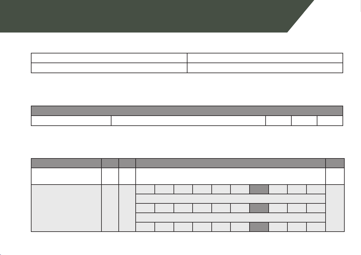
1.6.1 Relay Funcons
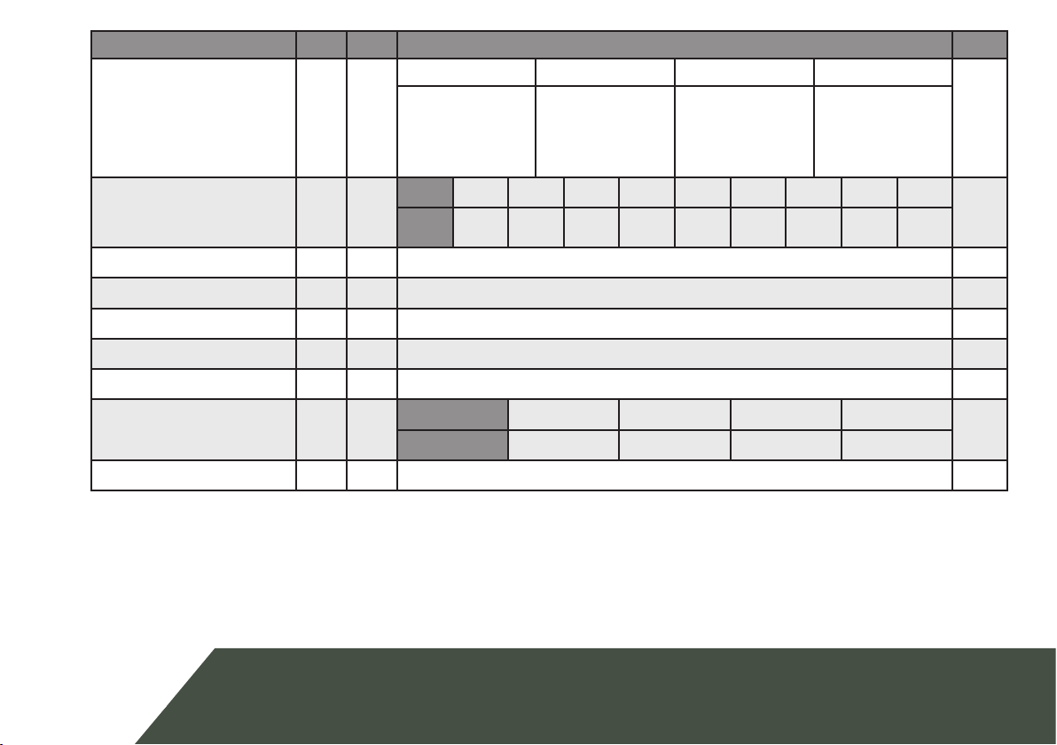
The table below is for use for the relay programming opons menoned in the table on the previous page.
Keys 3
and 4
Funcon Descripon
00 Fence Triggers when Zone 1 is Armed and Return Voltage is below the Threshold Voltage
01 Fence or O Triggers when Zone 1 is Disarmed or Return Voltage is below the Threshold Voltage
02 Armed Zone 1 is Armed
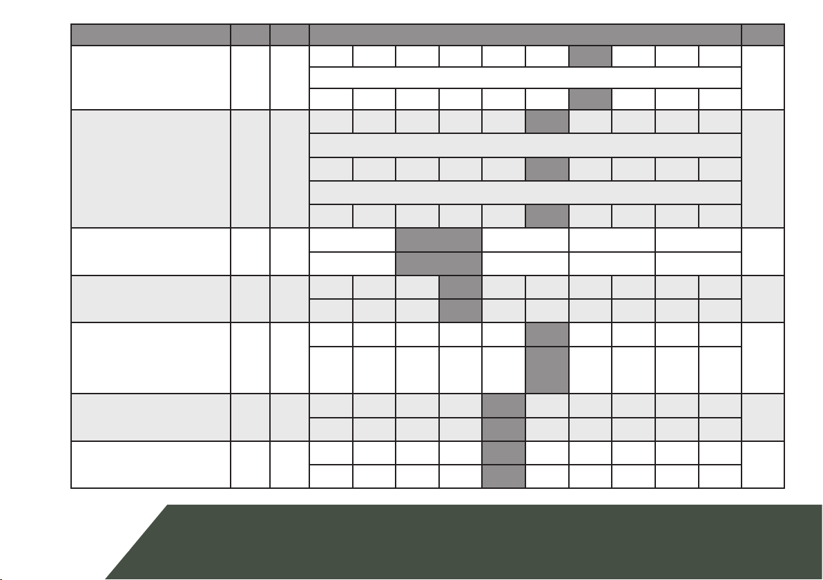
06 Fence Bi-Polar Triggers when energizer is Armed and the fence Return Voltage on either Bi-Polar re-
turn line has fallen below the Threshold Voltage
07 General Triggers on AC Fail, Tamper, Low Baery/Bad Baery, Gate Alarm or Internal error.
Latched (internal errors only)
08 Siren Triggers on Fence Alarm, Gate or Tamper. Will me out aer the Siren Time Out me.
Latched
09 Strobe Triggers on Fence alarm, Gate or Tamper. Only turns o on Energizer Disarm. Latched
10 AC Fail Triggers on AC Fail
11 Low/Bad Battery Triggers on Low or Bad Battery
12 Tamper Triggers when the case has been opened and J3 has been tted (Z14R only)
14 Gate Triggers on Gate Alarm
15 Siren Caused by
Gate
Behaves like siren, only for Gate Alarms
16 Armed - Low
Power Mode
Triggers when Armed in Low Power mode