KTI63194A3
SETUP
PLEASE REFER TO THE EXPLODED VIEW DRAWING IN THIS MANUAL IN ORDER TO IDENTIFY PARTS.
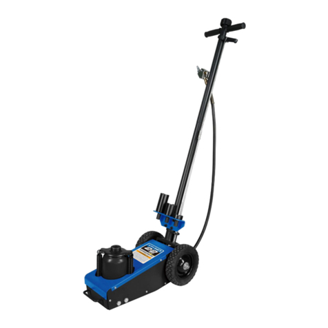
1. Feedtheblackhose(#64)andorangehose(#63)comingoutofthebottomofthehandleassembly(#76)throughthehandle-1(#52)whileat
thesametimelininguptheholeinthehandle-1(#52)withtheholeinthehandleconnector(#55).Securethemtogetherwiththescrew(#54).
2. Threadtwonuts(#53)allthewayonthebottomofthetierod(#50).Threadthebottomofthetierodallthewayinsidetheslottedpin
(#49).Nowtightenonenut(#53)downontopoftheslottedpin(#49)andtighten.Slipthespring(#51)downonthetierod(#50).Insertthe
tierod(#50)throughthebottomofthebracketthatisweldedtothehandle-1(#52)sothatthespringistrappedbetweenthebracketand
thenuts(#53)thataretightenedagainsttheslottedpin(#49).Compressthespringuntilthecrossholeinthetierod(#50)isvisibleonthe
othersideoftheweldedbracketandinstallther-pin(#71)throughthehole.
3. Threadanothernut(#53)allthewayonthetierod(#56).Holdthehandlelock(#58)downandawayfromthet-handle-2(#60)while
simultaneouslythreadingthetierod(#56)nutontothetierod(#50).
4. Raisethehandlelock(#58)upsotheslottedpin(#49)doesnotcomeincontactwithanyofthethreeholesinthehandleposition
seatassembly(#7).Removethescrew(#73)fromthehandlesocket(#11).Insertthehandle-1(#52)inthehandlesocket(#11)while
simultaneouslyinsertingtheslottedpin(#49)inthehandlesocket(#11)guideholes.Makesuretheholeinthelowerportionofthe
handle-1(#52)alignswiththethreadedholeinthehandlesocket(#11)andsecurethemtogetherwiththescrew(#73).Movethehandle
upanddownwhilesimultaneouslypullingthehandlelockdownsotheslottedpin(#49)willengagewithanyofthethreelockingholesin
thehandlepositionseatassembly(#7).Makesuretheslottedpinwillengageallthreeholes.Itmightbenecessarytoadjustthethreaded
connectionbetweentierods(#50and#56)inordertogetproperengagement.Afternaladjustment,tightenthenut(#53)tosecurethe
connection.
5. Therearetwoairhosesthatmustbermlyinsertedintothecouplers(#48).Theorangehose(#63)tsinthehigherlocatedcouplerwhile
theblackhose(#64)tsinthelowerlocatedcoupler.
6. Installtheairquickdisconnectofyourchoiceinthecrossvalve(#65).Putatleasttwowrapsofpipedopetapearoundthedisconnect
threads before installation to prevent air leaks.
7. Installthebracketassembly(#72)onthehandle-1tubeinthepositionasshownonthecoveroftheOwner’sManualandsecurethe
adaptorsinthebracketholesusingther-pins(#69).
8. Duetothevacuumreleasesystemdesignofthisjack,thejack’shydraulicsystemveryrarelybecomesairbound.Indicationofanair
bound system is a ram that does not rise smoothly. In some extreme case of an air bound system, air can be purged by following this
procedure:
PURGING AIR FROM THE HYDRAULIC SYSTEM
a. Raisetheram(#32)tomaximumheightandthenloweritallthewaydownfollowingtheactivationdirectionsontopofthehandle.
b. Repeatstep“a”severaltimesuntilallairispurgedfromthesystem.
OPERATING INSTRUCTIONS
This is the safety alert symbol used for the OPERATING INSTRUCTIONS section of this manual to alert you to potential
personal injury hazards. Obey all instructions to avoid possible injury or death.
IMPORTANT: Before attempting to raise any vehicle, check vehicle service manual for recommended lifting surfaces.
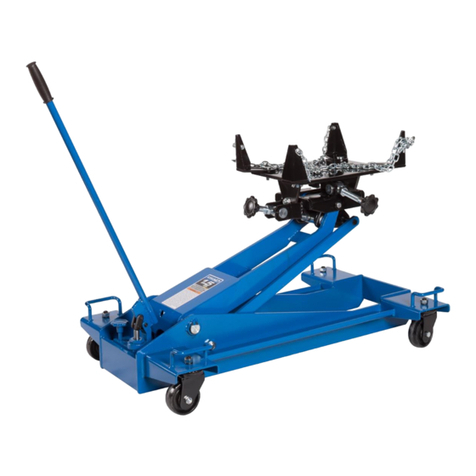
1. Becomefamiliarwiththeidenticationandfunctionoftheoperatingjackcomponents.
a. The ram
(#32)
is the shaft that comes out of the jack when you rotate the air lever to the right.
b. The ram
(#32)
is equipped with an extension screw which can be unscrewed to extend from the ram if there is not enough hydraulic
stroke to raise the load to the desired height. If additional height is required, extension adapters can be inserted in the hole on top of
the extension screw.
c. Largerdiametersaddlescanbeinsertedintheextensionscrewwhenrequiringalargerdiametersaddlesurface.
2. Chockthevehicle'stiresthatwillnotbeliftedoffthegroundpriortoliftingthevehicleandifavailable,applytheemergencybrakeorany
other method of braking.
3. Positionthejackatthedesignatedliftpoint.Estimatetherequiredramtraveltoraisethevehicletothedesiredheight.Ifthedesired
vehicle height exceeds the entire ram travel, unscrew the extension screw to make up the difference and add an extension adapter if
necessary.
4. Lockthehandleinapositionthatwillnotinterferewiththevehiclewhenraisedorlowered.Keepthehandleinthatlockedpositionuntil
the work is completed and you are ready to remove the jack from use.
5. Withthejackintheloweredposition,pushthejackunderthevehicle.IMPORTANT:Usethevehiclemanufacturer'srecommendedlifting
procedures and lifting points before lifting loads.
6. Inmostcases100psiginputairpressure(donotexceed200psig)willliftthemaximumcapacityloadnottoexceed22tons.Rotatethe
air lever to the right until the top of the ram comes close to the designated lift point. Make sure the designated lift point is at, parallel
tothegroundandfreefromgrease,anykindoflubricant,anddebris.Proceedwithpumpingthejackinordertoliftthevehicletothe
desiredheight.Duringlifting,inspectthepositionofthejackinrelationtothegroundandtheraminrelationshiptotheloadtopreventany
unstable conditions from developing. If conditions look like they are becoming unstable, slowly lower the load and make appropriate setup
corrections after the load is fully lowered.
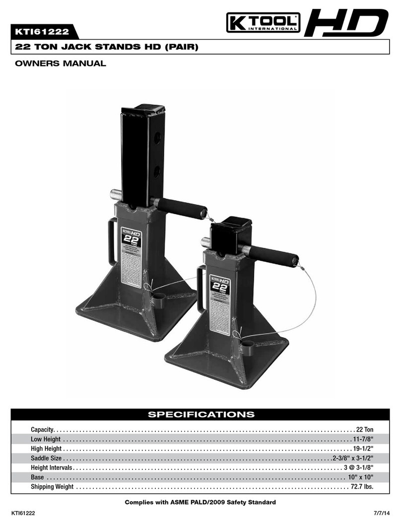
7.Whenthevehicleorloadisliftedtoitsdesiredheight,immediatelyplacesafetysupportstands(jackstands)intheirdesignated
locationsandadjustthestands'supportcolumnsupasclosetothedesignatedvehiclesupportpointsaspossible.Althoughjack
standsareindividuallyrated,theyaretobeusedinamatchedpairtosupportoneendofthevehicleonly.Standsarenottobeused
tosimultaneouslysupportbothendsoronesideofavehicle.Rotatetheairlevertothelefttolowerthevehicleontothesafetysupport
stands(jackstands).Makesurethevehicleissafelysupportedbythesafetysupportstands'(jackstands)saddlesandnotthelocating
lugsofthesaddles.Inspecttherelationshipofthesafetysupportstands(jackstands)withthegroundandthesafetysupportstand(jack
stand)columnsandsaddleswiththevehicletopreventanyunstableconditions.Ifconditionslookunstable,rotatetheairlevertotheright
toraisethevehicleoffthesafetysupportstands(jackstands).Maketheappropriatesetupchangesandslowlyandcarefullylowerthe
vehicle onto the safety support stand saddles.
8. Aftertheworkisdone,rotatetheairlevertotherightuntilthejackishighenoughtoremovethevehicleorloadfromthesafetysupport
stand saddles. Be sure load is stable. If it is not, lower load back onto safety support stands. Make appropriate setup corrections and
repeatthestepagain.Removethesafetysupportstandsfromunderthevehicle,beingverycarefulnottomovethevehicle.
9. Rotatetheairlevertothelefttolowerthevehicleorloaddowntotheground.
