KBC ESUGS4-P1-B User manual

ESUGS4-P1-B
Quick Start Guide
Rev 1912

ESUGS4-P1-B Quick Start Guide
QSG-ESUGS4-P1-B_Series-Rev1912 www.kbcnetworks.com
Copyright ©KBC Networks Networks Ltd. 2019
Page 2 of 12
Index
1 INTRODUCTION..........................................................................................................................................3
1.1 ESUGS4-P1-B Introduction .........................................................................................................3
1.2 Features..........................................................................................................................................3
1.3 Specifications.................................................................................................................................4
2 PANEL VIEWS .............................................................................................................................................5
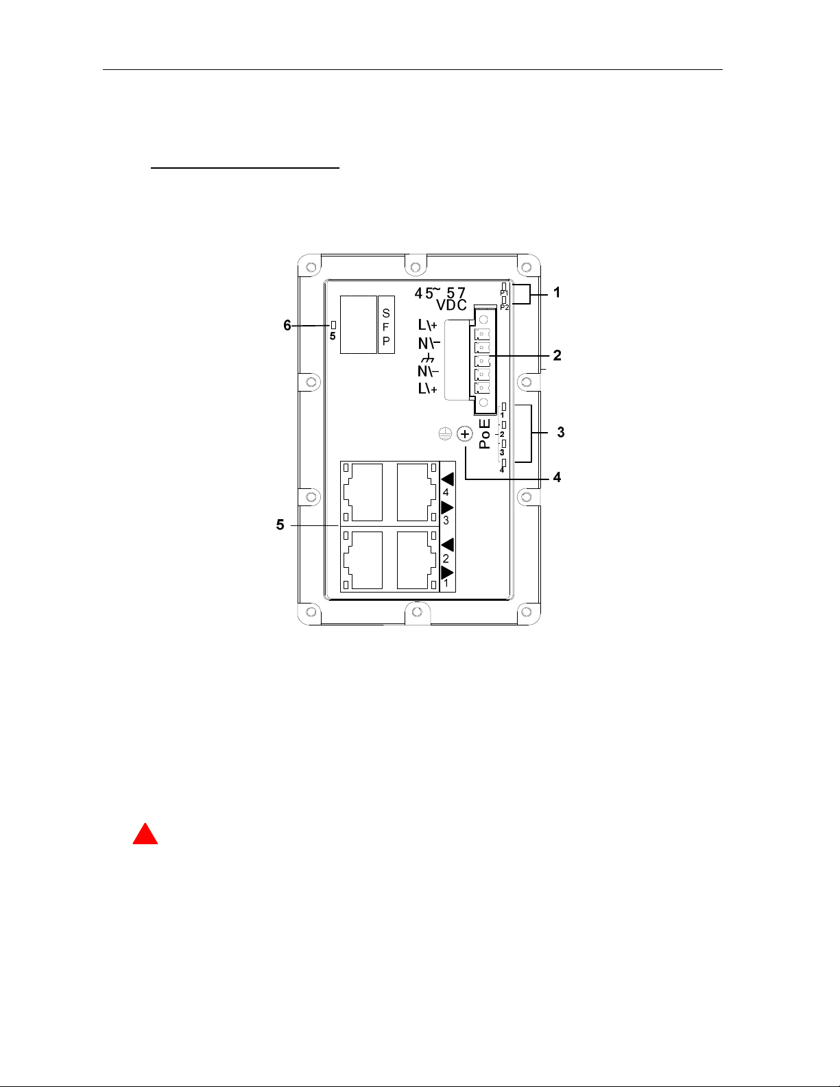
2.1 Front Panel View ...........................................................................................................................5
2.2 Status Indicator LED.....................................................................................................................6
3 DIMENSIONS (UNIT: mm) .........................................................................................................................7
4 MOUNTING ..................................................................................................................................................8
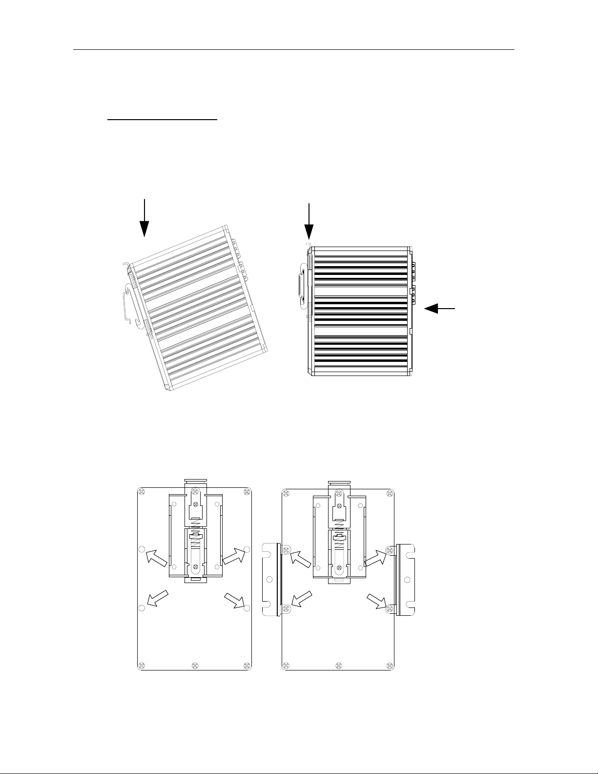
4.1 DIN Mounting.................................................................................................................................8
4.2 Wall Mounting ................................................................................................................................8
4.3 Items for Attention .........................................................................................................................9
4.4 Grounding.......................................................................................................................................9
5 CABLE.........................................................................................................................................................10
5.1 Ethernet Cable.............................................................................................................................10
5.2 SFP Port .......................................................................................................................................12

ESUGS4-P1-B Quick Start Guide
QSG-ESUGS4-P1-B_Series-Rev1912 www.kbcnetworks.com
Copyright ©KBC Networks Networks Ltd. 2019
Page 3 of 12
1 INTRODUCTION
1.1 ESUGS4-P1-B Introduction
ESUGS4-P1-B is an unmanaged PoE/PoE+ industrial Ethernet switch with
4*10/100/1000M auto sensing electrical ports and 1*1000M SFP uplink port. The
switch supports PoE/PoE+. Each electrical port outputs up to 30W. Industrial level 3
protection design and IP40 enclosure protection makes the product suitable for
applications in harsh environments.
1.2 Features
−Unmanaged industrial switch
−4*10/100/1000Base-T ports
−1*1000Base-X SFP port
−Support IEEE802.3af/at
−Dual 45~57VDC power input
−Level 3 ESD protection
−IP-40 housing design
−Operation temperature: -40~+75℃
−Support DIN-rail or wall mounted
−Unique DIN mount design makes mount and removal easy
−Installation: Plug-and-play, no setting required

ESUGS4-P1-B Quick Start Guide
QSG-ESUGS4-P1-B_Series-Rev1912 www.kbcnetworks.com
Copyright ©KBC Networks Networks Ltd. 2019
Page 4 of 12
1.3 Specifications
Ethernet
10/100/1000Base-T 4
1000Base-X SFP slot 1
PoE Standard IEEE802.3af/at
Switch Performance
Architecture Store and forward
Switch Capacity 10Gbps
Power
Redundant Input Power 45~57VDC, 5-pin screw terminal
Power Consumption (Max.) 5W (without PoE)
PSE Type End span
PoE Port Each port up to 30W
Overload Current Protection Present
Reverse Polarity Protection Present
Mechanical
Enclosure IP40
Dimension (L x W x H) 62 x 86.5 x 100mm
Weight 0.6kg
Environment
Storage Temperature -40 to +85℃(-40 to 185℉)
Operating Temperature -40 to +75℃(-40 to 167℉)
Operating Humidity 5% to 95% non-condensing

ESUGS4-P1-B Quick Start Guide
QSG-ESUGS4-P1-B_Series-Rev1912 www.kbcnetworks.com
Copyright ©KBC Networks Networks Ltd. 2019
Page 5 of 12
2 PANEL VIEWS
2.1 Front Panel View
1.PWR status indication
2.45~57VDC power input
3.PoE status indication
4.Grounding screw
5.10/100/1000Base-T port: #1 ~ #4
6.1000Base-X SFP port: #5
WARNING:This product MUST be mounted to a well-groundedmounting
surface such as a metal panel.

ESUGS4-P1-B Quick Start Guide
QSG-ESUGS4-P1-B_Series-Rev1912 www.kbcnetworks.com
Copyright ©KBC Networks Networks Ltd. 2019
Page 6 of 12
2.2 Status Indicator LED
LED Color Status Description
P1-P2 Orange
On Power is being supplied
Off Power is not being supplied
PoE1-4 Green
On The corresponding port’s PoE power on
Off The corresponding port’s PoE power off
SFP Port
LINK/ACT Green
On Port connected
Blinking Data is being transmitted
10/100/1000Base-T(X)
SPD Green
On Speed indicator for 1000Mbps
Off Speed indicator for 100Mbps and 10Mbps
LINK/ACT Orange
On The corresponding port’s link is active
Blinking Data is being transmitted
Off The corresponding port’s link is inactive

ESUGS4-P1-B Quick Start Guide
QSG-ESUGS4-P1-B_Series-Rev1912 www.kbcnetworks.com
Copyright ©KBC Networks Networks Ltd. 2019
Page 7 of 12
3 DIMENSIONS (UNIT:mm)
1
0
7
100

ESUGS4-P1-B Quick Start Guide
QSG-ESUGS4-P1-B_Series-Rev1912 www.kbcnetworks.com
Copyright ©KBC Networks Networks Ltd. 2019
Page 8 of 12
4 MOUNTING
4.1 DIN Mounting
Very simple: Press the clamp, insert into rail then loosen hand.
4.2 Wall Mounting
Step 1 Step 2

ESUGS4-P1-B Quick Start Guide
QSG-ESUGS4-P1-B_Series-Rev1912 www.kbcnetworks.com
Copyright ©KBC Networks Networks Ltd. 2019
Page 9 of 12
Step 1: Loosen the 4 screws on the rear panel;
Step 2: Mount the accessories on the rear panel;
Step 3: Fix the switch on the wall.
4.3 Items for Attention
−Operating Ambient: If the product is installed in a closed rack, the inside operating
ambient temperature of the rack may be higher than outside. Therefore,
consideration should be given to installing the equipment in an environment
compatible with the maximum operating temperature specified by the
manufacturer.
−Air Flow: Installation of the equipment in a rack should be such that the amount of
air flow required for safe operation of the equipment is not compromised.
−Circuit Overloading: Consideration should be given to the connection of the
equipment to the supply circuit and the effect that overloading of the circuits might
have on overcurrent protection and supply wiring.
−Reliable Earthing: Reliable earthing of rack-mounted equipment should be
maintained. Particular attention should be given to supply connections other than
direct connections to the branch circuit (e.g. use of power strips).
4.4 Grounding
Grounding and wire routing help limit the effects of noise due to electromagnetic
interference (EMI). Run the ground connection from ground screw to the grounding
surface prior to connecting devices.

ESUGS4-P1-B Quick Start Guide
QSG-ESUGS4-P1-B_Series-Rev1912 www.kbcnetworks.com
Copyright ©KBC Networks Networks Ltd. 2019
Page 10 of 12
5 CABLE
5.1 Ethernet Cable
The product uses standard Ethernet cable. Depending on the connection type, you
can choose CAT3, 4, 5e, 6 UTP cable to connect to other network devices
(computers, servers, switches, routers, hubs, etc.). The cable properties are listed in
the following table.
Cable Type Max Length Connector
10BASE-T Cat.3, 4, 5 100-ohm UTP 100 m (328 ft) RJ-45
100BASE-T Cat.5 100-ohm UTP UTP 100 m (328 ft) RJ-45
1000BASE-T
Cat.5/Cat.5e/6 100-ohm UTP
UTP 100 m (328ft) RJ-45
10/100/1000Base-T Pin Allocation
For 10/100/1000Base-T cable, pin 1 and 2 send data, pin 3 and 6 receive data.
10/100Base-T RJ-45 Pin Definition
Pin Number Signal PoE
1 TD+ PoE+
2 TD- PoE+
3 RD+ PoE-
4 null
5 null
6 RD- PoE-
7 null
8 null

ESUGS4-P1-B Quick Start Guide
QSG-ESUGS4-P1-B_Series-Rev1912 www.kbcnetworks.com
Copyright ©KBC Networks Networks Ltd. 2019
Page 11 of 12
1000Base-T RJ-45 Pin Definition
Pin Number Signal PoE
1 BI_DA+ PoE+
2 BI_DA- PoE+
3 BI_DB+ PoE-
4 BI_DC+
5 BI_DC-
6 BI_DB- PoE-
7 BI_DD+
8 BI_DD-
This switch supports MDI / MDIX auto-flip function. The following table lists
the10/100/1000Base-T MDI/MDI-X port pin output.
10/100Base-T MDI/MDI-X Pin Definition
Pin Definition MDI Port MDI-X Port PoE
1 TD+(transmit) RD+(receive) PoE+
2 TD-(transmit) RD-(receive) PoE+
3 RD+(receive) TD+(transmit) PoE-
4 Not used Not used
5 Not used Not used
6 RD-(receive) TD-(transmit) PoE-
7 Not used Not used
8 Not used Not used

ESUGS4-P1-B Quick Start Guide
QSG-ESUGS4-P1-B_Series-Rev1912 www.kbcnetworks.com
Copyright ©KBC Networks Networks Ltd. 2019
Page 12 of 12
1000Base-T MDI/MDI-X Pin Definition
Pin Number MDI Port MDI-X Port PoE
1 BI_DA+ BI_DB+ PoE+
2 BI_DA- BI_DB- PoE+
3 BI_DB+ BI_DA+ PoE-
4 BI_DC+ BI_DD+
5 BI_DC- BI_DD-
6 BI_DB BI_DA- PoE-
7 BI_DD+ BI_DC+
8 BI_DD- BI_DC-
5.2 SFP Port
SFP port supports both electrical and optical SFP modules. Select the right SFP
modules (rate, MM/SM, 1 fiber/2 fibers) on need basis. Please note that 1000M
SFP port supports 1000Mbps transmission rate only.
Need Help?
Please visit our website http://www.kbcnetworks.com or contact your nearest KBC
office or dealer.
Table of contents
Other KBC Switch manuals

KBC
KBC ESUGS8-P2-B User manual

KBC
KBC ESUL8P-PC2-D Series User manual

KBC
KBC ESUL8-D Series User manual

KBC
KBC ESUG4P-PG2-D Series User manual

KBC
KBC ESUL4-FL1 Series User manual

KBC
KBC ESMGS8-P4-B Series User manual

KBC
KBC ESUG8P-D Series User manual

KBC
KBC ESML6-FL2-M2 User manual

KBC
KBC ESUGS4-EG1-P1-D User manual

KBC
KBC ESUL8P-PC2-D User manual
Popular Switch manuals by other brands

H3C
H3C S9500 Series Operation manual

Dell
Dell PowerConnect 5316M quick guide

Moxa Technologies
Moxa Technologies EDS-316 Series Quick installation guide

Delta
Delta IPB-5-10A-S4 user manual

Videosec
Videosec PS04FE+2FE user guide

Chromalox
Chromalox PF207 Installation, operation and renewal parts identification