Kedacom IPC411 User manual

KEDACOM
User Manual for HD High Speed
Dome Camera
Version 02

i
Trademark
Kedacom™ and are trademarks of Suzhou Keda Technology Co., Ltd. in China and
various other countries. All other trademarks mentioned in this document are the property of their
respective holders.
Suzhou Keda Technology Co., Ltd.
131 Jinshan Road
New District, Suzhou, 215011
People's Republic of China
http://www.kedacom.com/en
Tel: +86-512-68418188
Fax: +86-512-68412699
© 2015 Suzhou Keda Technology Co., Ltd. All rights reserved.
Without the prior written permission of Suzhou Keda Technology Co., Ltd., any reproduction, translation
or retransmission of all or any part of this document for any purpose in either electronic or mechanical
form is not allowed.
Notice
The information in this document is subject to change without notice. Every effort has been made in the
preparation of this document to ensure accuracy of the contents, but all statements, information, and
recommendations in this document do not constitute a warranty of any kind, express or implied. Suzhou
Keda Technology Co., Ltd. is not responsible for printing or clerical errors.

ii
Target Audience
Administrators and Operators of Video Surveillance Products
Document Version
Version 02
Applicable Models
IPC411, IPC421, IPC415, IPC425
Related Document
Quick Start Guide for HD IP Camera IPC411&IPC421
Quick Start Guide for HD IP Camera IPC415&IPC425
Convention
Icon
Convention
Notes and warning: necessary
supplement of operations
Sign
Convention
BOLD
Menu, e.g. Drag to Zoom
>
Connector between menus of
different level, e.g. System
Setting>Basic Setting
Safety Instruction
These instructions are intended to ensure that the user can use the product correctly to avoid danger or property loss.
Please read this Guide carefully before using the product, and keep it properly for future reference. If the product
cannot work normally or is damaged because the user does not follow the safety instructions, we shall not assume
any responsibility.
1. Please adopt power supply in the safety voltage range.
2. If the product does not work properly, please contact your dealer or the nearest service center. Never attempt to
disassemble or repair the product yourself in any way.
3. Do not drop the camera or subject it to physical shock.
4. When cleaning the lens, please use a rubber dust blower to remove dust on the lens or filter, and usedry soft
cleaning cloth to remove the dirt on camera surface. For some hard dirt, user can apply some detergent to the
cleaning cloth and wipe gently. Never apply any volatile solvent, such as ethanol, benzene and diluents, to avoid
damage to surface coating.
5. Do not focus the camera lens on strong light such as the sun or incandescent lamp. The strong light can cause
overexposure or light leak (not camera malfunction), which may shorten camera lifetime.
6. Do not expose the camera in the environment not defined in the Manual. Maintenance and fee due to exposure
of product in the wrong conditions will be user‟s responsibility.
Operating Environment
Voltage
220V AC ±10%
Please use suitable external power adapter.
Temperature
Outdoor: -40℃~70℃
Indoor: -5℃~50℃
Humidity
10%~95% (RH, non-condensing)
Environment
Water-proof, Tamper-proof, Lightning-proof
7. Indoor Dome Camera cannot be installed at rainy or wet places. If the Indoor Dome Camera has a connecting
rod on the bracket, make sure there is no hole on the rod to avoid water.
8. Outdoor Dome Camera must be completely sealed to avoid dampness. Make sure there is no hole on the
connecting rod of bracket to avoid water.
9. While shipping the camera, pack it in the factory packing or use materials with equivalent quality.
10. When it is necessary to replace a part, please contact your dealer in advance and replace the part with specified
model or part of the same features. We shall not assume any responsibility for problems caused by unauthorized
replacement.
11. Keep the fiber interface clean. Dust may cause abnormality of the optical path.

High Speed Dome Camera User Manual
1
Contents
© 2015 Suzhou Keda Technology Co., Ltd. All rights reserved................................................................... i
Notice................................................................................................................................................................. i
Target Audience............................................................................................................................................... ii
1. Product Brief .......................................................................................................................................... 1
2. Start Up................................................................................................................................................... 3
2.1 Client Installation Conditions........................................................................................................... 3
2.2 Initial Configuration.......................................................................................................................... 3
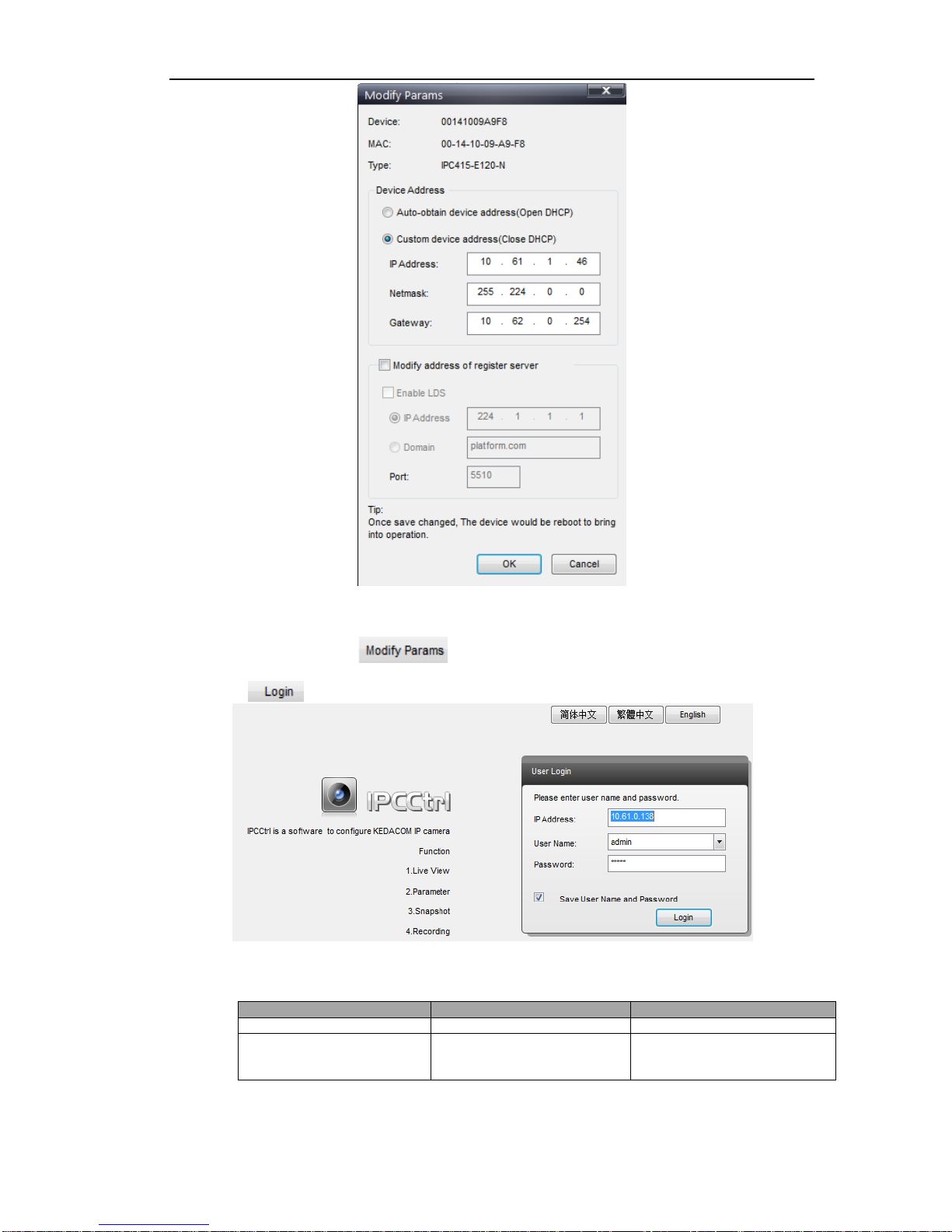
2.3 Modify Parameter ............................................................................................................................ 3
2.4 Login IPCCtrl ................................................................................................................................... 4
3. Product Functions ................................................................................................................................. 6
3.1 Live View.......................................................................................................................................... 6
3.1.1 Toolbar Buttons on Main Menu ................................................................................................. 6
3.1.2 Image Adjustment ..................................................................................................................... 7
3.1.3 PTZ Control............................................................................................................................... 9
3.2 Alarm Linkage................................................................................................................................13
3.2.1 Intelligent Alarm....................................................................................................................... 13
3.2.2 Parallel Port Alarm .................................................................................................................. 13
3.3 Privacy Mask .................................................................................................................................13
3.3.1 Set Area ...................................................................................................................................13
3.3.2 Clear Area................................................................................................................................ 14
3.3.3 Disable Function...................................................................................................................... 14
3.4 Snapshot........................................................................................................................................ 14
3.5 Recording ...................................................................................................................................... 14
3.5.1 Playback..................................................................................................................................14
3.5.2 Download ................................................................................................................................ 14
3.6 Upgrade.........................................................................................................................................15
3.6.1 Firmware Upgrade ..................................................................................................................15
3.6.2 PTZ Upgrade........................................................................................................................... 15
4. Parameter ............................................................................................................................................. 16
4.1 User Management.........................................................................................................................16
4.2 Text Overlay...................................................................................................................................16
4.3 BNC Output ................................................................................................................................... 16
4.4 Timing Task....................................................................................................................................17
4.5 Network Access.............................................................................................................................18
4.5.1 Ethernet...................................................................................................................................18
4.5.2 PPPoE.....................................................................................................................................18
4.6 Register to VMS.............................................................................................................................18
4.7 Dual-Stream...................................................................................................................................19
4.8 Camera Mode................................................................................................................................20
4.8.1 Configure Parameter............................................................................................................... 20
4.8.2 Import/Export Configuration....................................................................................................20
5. Appendix: Glossary of Terms............................................................................................................. 21

High Speed Dome Camera User Manual
1
1
1. Product Brief
High Speed Dome Camera (hereinafter referred to as Camera) is remote HD IP Camera based on IP network
technology. It encodes and transmits HD video. Also, it can be deployed at any point of a surveillance network and
transmits videos via public or private IP network.
There are indoor dome and outdoor dome cameras.
Picture 1-1 Outdoor Dome Camera Picture 1-2 Indoor Dome Camera
Picture 1-3 Indoor Dome Camera Without Cover

High Speed Dome Camera User Manual
2
2
Picture 1-3 IR High Speed Dome Camera

High Speed Dome Camera User Manual
3
3
2. Start Up
2.1 Client Installation Conditions
Operating System: Windows XP or newer versions
Browser: IE6.0 or newer versions
Processor: 2.0 GHz CORE®2 series or other equivalent processors
RAM Memory: 2GB or above
DirectX:9.0c
2.2 Initial Configuration
After installation, power on camera.
2.3 Modify Parameter
Main function of IPCSearch: the default setting of our camera is DHCP. If the IP address is unavailable or the
userneeds a static IP, please use IPCSearch to search cameras in LAN and modify parameter.
Operation Steps:
1) Get IPCSearch from the attached CD.
Picture 2-1IPCSearch
Note: IPCSearch is green software free from installation.
2) Run IPCSearch: it will search devices in LAN automatically and display the list as shown in
Picture2-1.
3) Select a camera to be configured, click or right click the mouse. Interface is shown
in Picture 2-2.

High Speed Dome Camera User Manual
4
4
Picture 2-2 Modify Parameter
2.4 Login IPCCtrl
1) After modification, will be disabled and the device will reboot automatically. Please
wait patiently. After reboot, the button will be enabled again. Please select this device again and click
or double click device name to enter web client. Interface is shown in Picture 2-3.
Picture 2-3IPCCtrl Login
2) Enter user name and password:
IPCCtrl accounts consist of both admin and guest users:
User Name
Initial Password
Authorization
admin
admin
perform full operations
guest
guest
live video view, image search,
video record search, video
playback
3) Interface after login is shown in Picture 2-4.

High Speed Dome Camera User Manual
5
5
Picture 2-4IPCCtrl Interface

High Speed Dome Camera User Manual
6
6
3. Product Functions
IPCCtrl can not only view live video, but also perform local snapshot and recording, and set alarm linkage. Some
models may not support some function below. User operation is subject to the actual functions of the model.
Note: Disabled button in IPCCtrl means the model doesn‟t support the function. Function with * in this Manual
means only some models support this function.
3.1 Live View
The default interface after user login is live video view, or user can click Live View to enter the interface.
3.1.1 Toolbar Buttons on Main Menu
Picture 3-1 Toolbar Buttons on Main Menu
Note: 1) PU Snapshot: PU Snapshots an image and sends it to local client in .JPG format. The image quality is
good, but there is some time delay caused by network.
2) Local Snapshot: Client snapshots an image and save it locally. The image quality is ordinary, but
there isn‟t any time delay.
View
Click this button to play live video.
Stop
Click this button to stop live view.
Call /
Click this button to call camera, and click again to stop calling. Not all cameras support this function.
Listen /
Click this button to listen to camera, and click again to stop listening. Not all cameras support this
function, and the local PC should be equipped with audio output device.
Full Screen
Click this button to display full screen.
When the image is displayed full screen, user can use a mouse to select PTZ up, down, left and right.
Snapshot /
Click this button to snapshoot an image.
Snapshot includes PU Snapshot and Local Snapshot . User can set in Parameter>Local
Setting.

High Speed Dome Camera User Manual
7
7
Picture 3-2 Snapshot Configuration
3.1.2 Image Adjustment
3.1.2.1 Focus
3.1.2.2 Zoom
3.1.2.3 Brightness
User can set or modify save path for PU Snapshot and Local Snapshot in Parameter>Local Setting,
as shown in Picture 3-2.
Recording /
Click this button to start recording and click again to stop recording. Recording is saved on local PC.
User can set or modify save path in Parameter>Local Setting.
Focus is to make image clear.
On the top of function buttons, click or (manual). When select manual focus,
(near) and (far) will pop up.
When PTZ control stops and auto focus is unnecessary, open Parameter>PTZ Function>Guard
Tour, and enableAuto Focus Stopped and set time (e.g. 10s), then lens will stop auto focus after
PTZ stops for this time duration (10s).
Zoom in or zoom out to suit different scenes.
Click to zoom out and to zoom in.
Note: In different scenes, the default angular speed of PTZ is the same. Enable Auto PT Speed to
set same linear speed of PTZ in different scenes.
Auto PT Speed can be set on Page 2 of function buttons. Check the checkbox to enable this function.
Due to low light situation, the image will look completely or partially dark and hard to recognize.
IPCCtrl provides the following functions to increase image brightness and ensure surveillance
quality.
Increase Image Brightness
In Image Adjustment part, user can drag Brightness slide bar to adjust image brightness.
Increase Lens Aperture
Aperture controls light input in lens. The larger the aperture is, the more light there will be and
the brighter the image will be.
Slower Shutter Speed
Camera shutter speed means the cycle of the sensor calculating light input amount. Therefore,
the slower the speed is, the brighter the image is.

High Speed Dome Camera User Manual
8
8
Note: If the target object is moving fast, this method is not applicable.
On Page 2 of function buttons, click to enable WDR and to disable WDR.
Enable Backlight
Backlight compensation can realize optimal exposure of target object under extremely strong
light. But it may make the bright zone grow white.
On Page 2 of function buttons, click to enable Backlight and to disable Backlight.
3.1.2.4 White Balance
3.1.2.5 Day/Night Mode
3.1.2.6 Noise Reduction
3.1.2.7 Auto Adjustment
3.1.2.8 Video Freeze
Click (Manual) on Page 2 of function buttons to select shutter speed, measured in
second (s).
Enable WDR
WDR can provide optimal exposure in intense backlight conditions.
The basic conception of White Balance is “to make all colors white regardless of the color
temperature of the light source”. It can compensate color rendition in pictures taken in specific
light source.
On Page 2 of function buttons, select White Balance Mode, Auto, Light or Manual.
After selecting Manual, enter Red Gain and Blue Gain respectively to adjust image colors.
Day (Night) Mode means disabling (enabling) IR lamp (only some models support), and the image
shifts to color (B/W), thus to get optimal images for day (sufficient light source) and night
(insufficient light source) conditions.
■On Page 1 of function buttons, click (Day Mode) and the image shifts to color.
Click (Night Mode) to and the image shifts to B/W.
Click (Auto) and the system will shift Day/Night Mode automatically according to
pre-set value.
■Open Parameter>Video Parameter>Camera Mode, set time duration and enable Night
Mode.
The camera will shift to night mode in the preset time duration.
Note: User can set other parameters under Night Mode, such as Shutter Priority, Aperture Priority,
Brightness, Contrast, Saturation and Sharpness.
When there are many noise points caused by environment and camera lens, Noise Reduction
function can be enabled to adjust images.
On Page 6 of function buttons, select Noise Reduction mode, or (manual).
Manual mode includes 15 levels.
Click to disable this function.
Auto Adjustment applies default settings of the camera block, which are suitable for most
conditions.
On Page 1 of function buttons, click (All auto adjustments), and all parameters will
restore to default values.
On Page 5 of function buttons, select this function and the video will display the last frame
image before clicking. Click to disable freeze.

High Speed Dome Camera User Manual
9
9
3.1.2.9 Drag to Zoom
Picture 3-3 Drag to Zoom
3.1.3 PTZ Control
The High Speed Dome Camera is equipped with PTZ for wide-range patrol, which enlarges surveillance scope. User
can control PTZ through IPCCtrl.
3.1.3.1 Manual Control
Direction Key Adjustment
Click (direction keys) in PTZ control area to adjust PTZ to ideal position. PTZ control area is on
the top left of live view window, as shown in Picture 3-4.
Step Length
Step Length is the rotation distance of PTZ when click on the direction keys.
Drag the slider bar to adjust PTZ step length, as shown in Picture 3-4.
Picture 3-4 PTZ Control
Accurate Positioning
Input values to adjust PTZ to a specific position accurately. On Page 3 of function buttons, input a number in the
textbox under Pan and Tilt, and click (Set) to configure current lens.
Click (Query) to query current position, and result will display in the textbox under Pan and Tilt.
Definition: Drag to Zoom function centers the selected area and zooms in the area to full
screen.
Enable:Right click the image and click Drag to Zoom on the popup menu to enable the function;
or check Drag to Zoom on the bottom of Page 1 of function buttons.
Start: Drag an area (left to right) with mouse to zoom in and center it.
Cancel: Drag a reverse rectangle (right to left) with mouse to cancel zoom and center.
Disable: Right click the image and click Drag to Zoom on the popup menu to disable the
function; or uncheck Drag to Zoom on the bottom of Page 1 of function buttons.

High Speed Dome Camera User Manual
10
10
3.1.3.2 Auto Patrol
Auto Patrol function can realize shift between different positions. These positions are called Preset Positions, which
shall be preset be user.
Configure Preset Position
Adjust PTZ and field of view to ideal position, set preset position number on Page 1 of function buttons
and click (Set) to save current preset position. Click (Remove) to remove preset position and reset.
Also, user can set preset position through Parameter interface. Open Parameter>PTZ Function>Preset Settings, set
Preset No., modify Preset Name and click . Click to cancel preset position and reset. Click
to load preset position.
Load Preset Position
On Page 1 of function buttons, click (Load Preset Position) and PTZ will rotate to the preset position
immediately.
When power on, camera will rotate to mechanical zero by default. Set preset position, and enable function of Power
on to Load Preset Position, then camera will load preset position automatically after power on.
Open Parameter>PTZ Function>Guard Tour, enable Power Loss Recovery, select Power on to Load Preset Position
and input the preset position number.
Picture 3-5 PTZ Function>Guard Tour
Power Loss Recovery: Select Power Loss Recovery from the drop-down list. When PTZ stays at the same position
for a certain preset time, camera will remember the position and load this position automatically when the camera is
rebooted. Default preset time is 30 seconds.
Picture 3-6 PTZ Function>Guard Tour>Power Loss Recovery
Preset Position Patrol: After set multiple preset positions, click (Start) on Page 1 of function buttons, and
camera will patrol among random 8 preset positions. Click (Stop) to disable preset position patrol.
Also, user can set Preset Position Patrol in Parameter. Open Parameter>PTZ Function>Preset Position Setting:

High Speed Dome Camera User Manual
11
11
Picture 3-7 Parameter>PTZ Function>Preset Setting
Patrol Position: serial number of patrol position, cannot be modified.
Preset Position No.: can be modified. Click Preset Position No. to modify. User can select a preset position
randomly from 255 positions, and preset position cannot be selected repeatedly.
Stay Time: can be modified. Click Stay Time to set stay time for each preset position, time range 5 to1800 seconds.
Default stay time is 10 seconds.
Enable/Disable: “Yes” means the preset position has been set already; “No” means the preset position has not been
set. When camera patrols to the unset preset position, it will skip directly and go to the next preset position.
Auto Guard Tour: Run operations of Load Preset/ Preset Patrol/Pan Patrol/Tilt Patrol/Frame Patrol/ Random Patrol/
Pano Patrol/ Variety Patrol automatically.Open Parameter>PTZ Function> Guard Tour, checkEnable Auto Guard
Tour,and select operation from the drop-down list.
Picture 3-8 PTZ Function> Guard Tour>Enable Auto Guard Tour
Load Preset:After stop operating on camera for a certain period of time, the lens will return to the defined preset
position automatically. The time duration is configurable, and default value is 3 minutes.
Preset Patrol: After stop operating on camera for a certain period of time, the lens will enable Preset Position Patrol
automatically. The time duration is configurable, and default value is 1 minute.
Tilt Patrol: When Auto Reverse is enabled, camera will patrol vertically from -5°to 185°; otherwise, camera patrols
vertically from -5°to 90°.
Pan Patrol: Camera patrols horizontally from 0°to 360°.
Frame Patrol: In every key frame interval, camera automatically rotates horizontally by 90°.
Random Patrol: Camera automatically patrols horizontally at random.
Pano Patrol: Camera patrols panoramically from 0°to 180°in vertical direction and from 0°to 360°in horizontal
direction.
Variety Patrol: Camera patrols automatically in a variety of paths. Details can be referred to in Variety Patrol.
Manual Patrol: Camera patrols among 32 preset positions successively, and the process of the patrol is Manual
Patrol. Currently, Path 1 includes No. 1 to No. 32 preset positions, and Path 2 includes No. 33 to No. 64 preset
positions. The rest is in the same manner.
On Page 5 of function buttons, select path number and click to enable Manual Patrol.

High Speed Dome Camera User Manual
12
12
After enable this function, camera will patrol among all valid preset positions on a certain path, and the stay time on
each position is 10 seconds.
Click any PTZ control button to disable this function.
Pan Patrol: PTZ rotates in horizontal direction.
Tilt Patrol:PTZ rotates in vertical direction.On Page 1 of function buttons, click (Start Pan Patrol) to start Pan
Patrol, (StartTilt Patrol) to start Tilt Patrol, and (Stop Patrol) to Stop Patrol. Input a value (1 ~ 40) in Patrol
Speed to adjust rotate speed.
3.1.3.3 Reverse
The vertical rotation angle of PTZ is limited, and reverse function can make PTZ control more convenient.
Auto Reverse: If this function is enabled, when camera rotates till tilt 90°, it will reverse pan 180°automatically and go
on rotating.
On Page 5 of function buttons, enable function of Auto Reverse.
Picture 3-9 Auto Reverse
Image Flip: Flip image vertically or horizontally.
On Page 5 of function buttons, click or to enable Image Flip. Click again to restore image.
3.1.3.4 Restrict PTZ
It is to restrict PTZ rotation in user-defined area.
Restrict Patrol: Adjust PTZ to the limit position, and click (Left) and (Right) on Page 3 of function buttons
to save limit positions.
Manual Restrict Patrol: When control PTZ manually, restrict PTZ rotation area.After Set Pan Area, open Manual
Restrict Patrol on Page 3 of function buttons.
Auto Restrict Patrol: Restrict PTZ rotation area during patrol.After Set Pan Area, openAuto Restrict Patrol on Page
3 of function buttons.
Remove Restriction: Remove PTZ limits.On Page 3 of function buttons, click and at the same position
respectively to remove PTZ restriction.
3.1.3.5 PTZ Reset
Pan Zero is the mechanical zero of PTZ after camera start.
Reset means returning to the original position and maximizing the view field.

High Speed Dome Camera User Manual
13
13
Reset: Click (Reset) to make PTZ return to the original position and maximize the view field. Reset is in the
center of PTZ control keys.
Pan Zero Correction:Reset PTZ to the mechanical zero. On Page 3 of function buttons, click (Pan Zero
Correction).
3.1.3.6 Variety Patrol
Variety Patrol means camera patrols according to the PTZ movement trails in a recorded duration.
On Page 7 of function buttons, set Variety Patrol Paths, and 4 paths can be configured.
Start Rec.: Select a Variety Path, click , operate PTZ control of , and record PTZ
rotation, step and zoom. Click to stop recording. Each path can be maximum 10 minutes. Click
to view all operations.
Remove Rec.: Select a Variety Path, and click to remove all recorded PTZ operations on this path.
3.2 Alarm Linkage
Alarm Linkage settings: Intelligent Alarm, Parallel Port Alarm connecting to alarm output device.
3.2.1 Intelligent Alarm
Detect movements in the defined area. Once the movement exceeds the defined sensitivity, an alarm will be
triggered. Alarm Recovery Time can be set 0~300s, and default is 5s.
Set Area: Check Parameter>Video Parameter>Intelligent Alarm to check Enable Intelligent Alarm. Select
Motion Detection from the drop-down list, and set detection area.Click a square and it will turn purple red. Start
from this square and draw an area to be the detection area,which will turn purple red. Camera can be set 4
areas of Motion Detection.
Clear Area: Start from an undefined square and draw an area that contains the defined area, or click the
defined squares one by one to clear setting. Save to make settings effective.
Disable Function: To disable this function, uncheck the checkbox Enable Intelligent Alarm.
3.2.2 Parallel Port Alarm
OpenParameter>Parallel Port Alarm. Parameters are as follows:
Parameter
Explanation
Alarm Name
Alarm input device name, such as Front Door
Smoke Detector
Alarm Input Type
Always Open or Always Close for option
Linked Camera
Support
Alarm Output
Select output devices such as alarm bell or
spray.
Select “No Output” and no alarm linkage will
be triggered except Alarm Text.
Alarm Scheme
Select alarm detection and duration.
Select “No Detection” and effect will be the
same as above, neither will alarm text
overlaid.
When select “Specific Duration”, set alarm
detection duration.
3.3 Privacy Mask
Mask sensitive and private part of the image so as to keep sensitive information private.
3.3.1 Set Area
1) Check Parameter>Video Parameter>Privacy Mask to set privacy mask area.
2) Check Enable Privacy Mask.
3) Click a square and it will turn purple red. Start from this square and draw an area to be the masking
area, which will turn purple red.
.
The image is divided into 16 columns and 12 rows of small squares. The maximum masking area
can be 24 squares. The maximum number of Privacy Mask area is 4.

High Speed Dome Camera User Manual
14
14
4) Click under the view window or click to reset the area.
3.3.2 Clear Area
3.3.3 Disable Function
To disable this function, uncheck the checkbox Enable Privacy Mask.
3.4 Snapshot
Click to enter snapshot management interface. User can perform operations on snapshots in SD
card, such as view, delete and download.
Note: If the Snapshot interface is disabled, please confirm the SD card is inserted and then reboot client.
Operation Steps
1) Search snapshots: search those pictures within the defined duration from the SD card.
2) On the snapshot list, select searched picture and perform operations such as view, delete and
download.
3.5 Recording
Click to enter recording management interface. User can perform operations on recordings in SD
card, such as playback, delete and download. (A SD card must be inserted in the camera.)
Note: If the Recording interface is disabled, please confirm the SD card is inserted and then reboot client.
Note: Record Modeincludes:Start Recording When Disconnected, Recording All the Time, and Stop
Recording, configurable in Parameter>Recording Parameter.
Picture 3-10 Recording
3.5.1 Playback
1) Select Recording Duration from Calendar.
2) If there is background color on a date, it means there is recording on that day. Select duration of the
date and the video will be displayed directly in the right window.
3.5.2 Download
Start from an undefined square and draw an area that contains the defined area, or click the defined
squares one by one to clear setting. Save to make settings effective.
Select Recording Duration from calendar and download recording to local PC, download path
configurable.

High Speed Dome Camera User Manual
15
15
3.6 Upgrade
3.6.1 Firmware Upgrade
Picture 3-11 Firmware Upgrade
2) Select local upgrade file (<*.pkg> or <*.img> format).
3) During upgrading, please do nothing but waiting.
4) After upgrading, please download ActiveX control again. After finishing it, reboot browser.
Note: Please click “Upgrade” during system upgrading, and the upgrade file is usually in <*.pkg> or <*.img>
format.
1) Run IPCSearch.
2) Click to upgrade firmware of cameras of the same model simultaneously.
3.6.2 PTZ Upgrade
1. Open Parameter> PTZ Function> PTZ Maintenance>Upgrade.
2. Select local upgrade file (Contact dealer for the latest file in <*.bin> format).
3. During upgrade, please wait patiently.
Note: PTZ upgrade is the firmware upgrade of high speed dome camera. Usually it is unnecessary. If
necessary, please operate carefully or contact dealer or customer service staff for upgrade.
3.6.3 IPCCtrl Upgrade
Note: For detailed operation instructions of IPCCtrl, please refer to the help document.
Contact dealer for upgrade file.
Method 1
1) Enter IPCCtrl interface Parameter>System Maintenance> Upgrade, as shown in Picture 3-11.
Method 2
After firmware upgrade, please login web client again. The page will prompt to download a new
ActiveX control. After downloading it, client upgrade will be completed. Login again to enter the latest
IPCCtrl.

High Speed Dome Camera User Manual
16
16
4. Parameter
Some models may not support some function below. User operation is subject to the actual functions of the model.
4.1 User Management
Admin user has the authorization to modify passwords of IPCCtrl admin user and guest user.
Modification method:
1) Open Parameter>System Setting>User Management
2) Check the checkbox of the item to be modified, the password area will be enabled and editable.
3) Enter new password.
4) Confirm new password.
5) Click Save to validate setting, and Reset to quit modification.
4.2 Text Overlay
Display preset text on the surveillance window, configuration steps as follows:
1) Open Parameter>Video Parameter>Text Overlay, and click , as shown in Picture 4-1.
Picture 4-1Text Overlay
2) Check Edit Text checkbox to enable required OSD.
Note: Different models may support different numbers of OSD. Configuration is subject to actual camera
model.
3) Double click user-defined OSD to input text content. Each OSD supports maximally 3 lines of text.
User can check Align Right checkbox to align texts on the right, or the default setting is “align
left”.
4) Drag text to the ideal position in the view window.
5) Click Save to validate settings, and Reset to quit edit.
4.3 BNC Output
Camera with BNC output can output analog image directly when local display function is enabled.
Open Parameter>Video Parameter>Camera Parameter, select „Start‟ from the BNC Output drop-down list and
set the CVBS Video Mode, as shown below.
This manual suits for next models
3
Table of contents
Other Kedacom Security Camera manuals

Kedacom
Kedacom IPC2860 Series User manual

Kedacom
Kedacom IPC425 User manual

Kedacom
Kedacom IPC425 User manual

Kedacom
Kedacom IPC4X2 Series User manual

Kedacom
Kedacom IPC981 User manual

Kedacom
Kedacom IPC2240-HN-SIR30 User manual

Kedacom
Kedacom IPC2860-HN-PIR15 User manual

Kedacom
Kedacom IPC Series User manual

Kedacom
Kedacom IPC427-D120-N User manual

Kedacom
Kedacom IPC2255-Gi4N Series User manual