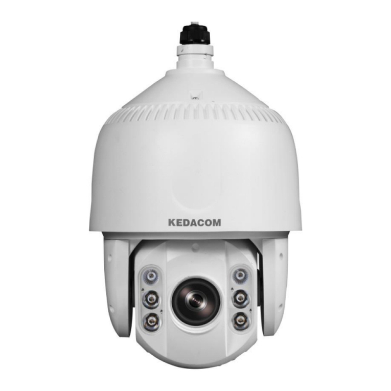
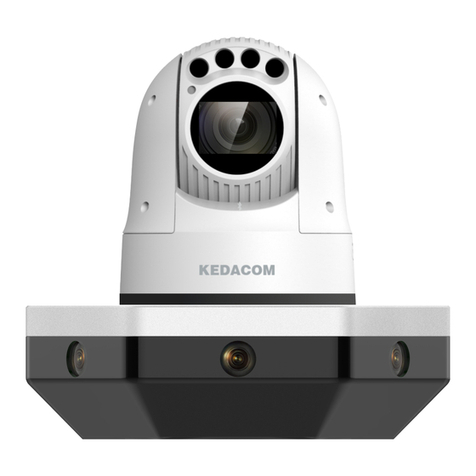
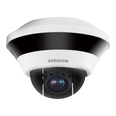
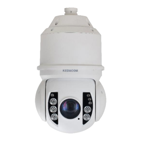
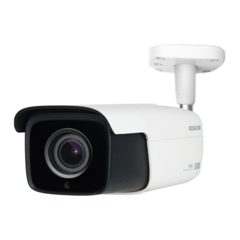
Kedacom IPC Series User manual

KEDACOM
User Manual for HD IP Camera of
IPC Series
V3 (Mar, 2018)

2
Trademark
Kedacom™ and are trademarks of Suzhou Keda Technology Co., Ltd. in
China and various other countries. All other trademarks mentioned in this document are
the property of their respective holders.
Suzhou Keda Technology Co., Ltd.
131 Jinshan Road
New District, Suzhou, 215011
People's Republic of China
http://www.kedacom.com/en
Tel: +86-512-68418188
Fax: +86-512-68412699
© 2018 Suzhou Keda Technology Co., Ltd. All rights reserved.
Without the prior written permission of Suzhou Keda Technology Co., Ltd., any
reproduction, translation or retransmission of all or any part of this document for any
purpose in either electronic or mechanical form is not allowed.
Notice
The information in this document is subject to change without Note. Every effort has been
made in the preparation of this document to ensure accuracy of the contents, but all
statements, information, and recommendations in this document do not constitute a
warranty of any kind, express or implied. Suzhou Keda Technology Co., Ltd. is not
responsible for printing or clerical errors.

3
Target Audience
Administrators and Operators of Video Surveillance Products
Document Version
V3
Applicable Models
IPC1X3 series
IPC185 series
IPC2X51 series
IPC2X52 series
IPC2X53 series
IPC2255 series
IPC2X10 series
IPC2X31, IPC2X32 series
IPC2X11 series
IPC2X40 series
IPC2X33 series
Related Document
Quick Start Guide
Convention
Icon
Convention
Notes
italic
Book or document name;
Filling content
>
Connector between menus of different level
BOLD
Menu; Button; Option
UL Safety Instruction
CAUTION: Risk of Explosion if Battery is replaced by an Incorrect Type. Dispose of Used
Batteries According to the Instructions.
Suitable for Mounting on Concrete or Other Non-Combustible Surface Only.

4
This product is intended to be supplied by a Listed Power Unit, output rated minimum 24Vac,
50/60HZ, 0.5A or 12Vdc, 0.8A or POE,0.5A,non-energy hazards and Tma=60Deg.C. complied
with LPS.
a. the function of the ITE being investigated to IEC 60950-1 is considered not likely to
require connection to an Ethernet network with outside plant routing, including campus
environment; and
b. the installation instructions clearly state that the ITE is to be connected only to PoE
networks without routing to the outside plant.

5
Contents
1. Product Brief.....................................................................................................................................1
2. Appearance......................................................................................................................................2
3. Start Up ............................................................................................................................................6
3.1 Client Installation Conditions................................................................................................6
3.2 Initial Configuration ..............................................................................................................6
3.2.1 Modify Parameter.......................................................................................................6
3.2.2 Login Web Client........................................................................................................8
3.2.3 Login to the Web Client Interface .............................................................................10
3.2.4 Focus........................................................................................................................10
4. Product Functions...........................................................................................................................12
4.1 Live View............................................................................................................................12
4.1.1 Toolbar Buttons........................................................................................................12
4.1.2 Image Adjustment ....................................................................................................14
4.1.2.1 Aperture...............................................................................................................14
4.1.2.2 Brightness............................................................................................................14
4.1.2.3 White Balance......................................................................................................15
4.1.2.4 Night Cut..............................................................................................................16
4.1.2.5 Noise Reduction...................................................................................................16
4.1.2.6 *Distortion Correction...........................................................................................16
4.1.2.7 *Remote Zoom In.................................................................................................17
4.1.2.8 Defog ...................................................................................................................18
4.1.2.9 *EIS......................................................................................................................18
4.1.2.10 Rotate and BNC...................................................................................................18
4.1.3 Auxiliary Function.....................................................................................................18
4.2 Motion Detection................................................................................................................18
4.2.1 Set Area ...................................................................................................................19
4.2.2 Clear Area................................................................................................................20

4.2.3 Disable Function.......................................................................................................20

6
4.3 Tampering..........................................................................................................................20
4.4 *Guard Line........................................................................................................................21
4.5 *Defocus ............................................................................................................................23
4.6 *Scene Change..................................................................................................................23
4.7 *Enter Guard Area..............................................................................................................24
4.8 *Exit Guard Area................................................................................................................26
4.9 *Object Left ........................................................................................................................26
4.10 *Object Removal................................................................................................................26
4.11 *Gathering..........................................................................................................................26
4.12 *Audio Surge......................................................................................................................26
4.13 *Alarm Linkage...................................................................................................................27
4.13.1 Motion Detection Alarm Linkage..........................................................................28
4.13.2 Tampering Alarm Linkage....................................................................................28
4.13.3 Alarm Input Linkage.............................................................................................29
4.13.4 Abnormality Linkage.............................................................................................30
4.14 ROI.....................................................................................................................................31
4.14.1 Set........................................................................................................................31
4.14.2 Clear ....................................................................................................................31
4.14.3 Disable.................................................................................................................31
4.15 Privacy Mask......................................................................................................................31
4.15.1 Set........................................................................................................................32
4.15.2 Clear ....................................................................................................................32
4.15.3 Disable.................................................................................................................32
4.16 Video Info Overlay..............................................................................................................32
4.17 *SDI Output........................................................................................................................33
4.18 *Snapshot ..........................................................................................................................34

7
4.19 *Playback...........................................................................................................................34
4.19.1 Playback ..............................................................................................................35
4.19.2 Download.............................................................................................................35
4.20 Upgrade .............................................................................................................................35
4.20.1 Firmware Upgrade ...............................................................................................35
4.20.2 Web Client Upgrade.............................................................................................36
4.20.3 Restoration...........................................................................................................37
5. Settings .........................................................................................................................................39
5.1 Network Access .................................................................................................................39
5.1.1 Ethernet....................................................................................................................39
5.1.2 PPPoE......................................................................................................................39
5.2 Register to VMS.................................................................................................................40
5.3 BNC Output........................................................................................................................40
5.4 User Security......................................................................................................................41
5.4.1 User Management....................................................................................................41
5.4.2 IP Filter.....................................................................................................................41
5.4.3 Security Service .......................................................................................................42
5.5 Text Overlay.......................................................................................................................42
5.6 Video Encoding..................................................................................................................43
6. Appendix: Glossary of Terms......................................................................................................45

HD IP Camera User Manual
1
1. Product Brief
HD IP Camera (hereinafter referred to as Camera) is a remote video surveillance device based on IP
network technology. It encodes and transmits HD video.
Some features of the HD IP camera:
Live View
Apply high-performance progressive scan sensor, with clear image and vivid color;
High-performance video processing chip and efficient video encoding, providing HD video image;
Dual-stream to fit different network bandwidth;
Configurable text overlay on video image;
Alarm
With audio and alarm connectors, realize functions of talkback and alarm;
Motion detection and alarm linkage, make video surveillance intelligent;
Support alarm linkage edit: Alarm Text Overlay, Device Output, Live View Display and etc.
Networking
Static address, DHCP or PPPoE;
NAT traversal, DNS and multicast technology
Storage
With storage card slot, when the network breaks down, video can be stored in local storage card;
Support local snapshot, default format is .JPG;
Support local recording, user can query and playback recording on PC.

HD IP Camera User Manual
2
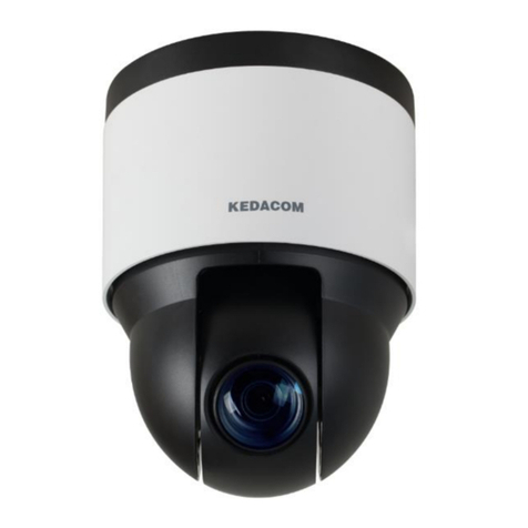
2. Appearance
Picture 2-1 IPC113 / IPC123 / IPC143 series
Picture 2-2 IPC185 series
Picture 2-3 IPC2251 series
Picture 2-4 IPC2451 series

HD IP Camera User Manual
3
Picture 2-5 IPC2255-GN series
Picture 2-6 IPC2152 / IPC2252 / IPC2452 series

HD IP Camera User Manual
4
Note: Different sub-models may have some difference in their appearance. Device appearance is
subject to the actual model.
Picture 2-7 IPC2253 / IPC2453 series
Picture 2-8 IPC2110 / IPC2210 series
Picture 2-9 IPC2131 / IPC2132 / IPC2231 / IPC2431 series
Picture 2-10 IPC2233 / IPC2433 series

HD IP Camera User Manual
5
Picture 2-11 IPC2111 / IPC2211 / IPC2411 series
Picture 2-12 IPC2140/ 2240 / 2440 series

6
3. Start Up
Please refer to the Quick Start Guide in the packing for device installation and wiring.
3.1 Client Installation Conditions
Requirements of PC for installing the client:
Operating System: Windows XP or newer versions
Browser: IE7.0 or later versions, Firefox, Google Chrome (41 and below versions)
Processor: 3.3 GHz CORE®i3 series and later version or other equivalent processors
RAM Memory: 4GB or above
DirectX:9.0c
We will take IE8.0 as an example.
3.2 Initial Configuration
After installation and wiring, electrify the camera.
3.2.1 Modify Parameter
1) Get IPCSearch from the attached CD.
Picture 3-1 IPCSearch
Note: Camera name is subject to the search result.
2) Run IPCSearch: it will search devices in LAN automatically and display the list as
shown in Picture 3-1.
3) When login to a non-activated camera for the first time, activate it first. Select the
device and click “Batch processing”. In the popup interface, set admin user’s
password and the email address to find back the password. Click “Activate”and
wait for rebooting, as shown in Picture 3-2.

7
Picture 3-2 Activate camera
4) Select a camera to be configured, click “Modify Params”or right click the mouse.
Interface is shown in Picture 3-3. Modify parameters and fill admin user name
(admin) and the password set when activating the device.
Picture3-3 Modify Parameter
5) Click “OK”and in the popup window click “OK”. Wait for rebooting.

8
Picture 3-4 Reboot device
3.2.2 Login Web Client
1) After modification, camera will reboot automatically. Please wait patiently. After
reboot, the button will be enabled again. Please select this device again and click
“Login” or double click device name to enter web client. Interface is shown in Picture
3-5.
Picture 3-5 Web Client Login Interface
Note: If log in the non-activated device through web client for the first time, user can set
admin password and activate the device in the login interface, as shown below.
Note:
1) To ensure the safety of device on internet, it is strongly recommended that you set a
strong password which is composed of at least 2 kinds of the following, digits,
case-sensitive letters or specific symbols, and whose length ranges from 8 to 16
bits.
2) Please modify the password periodically and once every 3 months is recommended.
If the device is used in highly risky environment, suggest modifying the password
monthly or weekly.
3) Please keep your user name and password safe.

9
Picture 3-6 First login through web client
2) If user enters a wrong user name or password for 3 times, the camera IP will be
locked up for 10 minutes, during which user cannot login to this camera. If user
forgets the password, reset the password. Click “Password Reset“and a window
will pop up, as shown below.
Picture 3-7 Password Reset
3) Click the password reset link first and fill in the Serial Number and Email address.
Then login to the email address to get a security code and fill in “Command”blank
and click “OK”. Please remember the new password (admin123 by default) shown in
the popup window and click “OK”. The device will reboot. After resetting the
password, re-login the web client and configure the device. Alternatively, scan the
QR code in Picture 3-7 with a mobile device and complete this step.

10
Picture 3-8 Password reset
3.2.3 Login to the Web Client Interface
Enter user name and password: when login successfully for the first time, download and
install the plug-in. Close browser when installing. After finishing, double-click the device in
IPCSearch to open browser and enter user name and password. Interface after login is
shown below.
Picture 3-9 Web Client Interface
3.2.4 Focus
It is the process of imaging the target object clearly. Please focus according to the
lens type of camera:
*Mechanical Focus: View live video on web client and adjust the focus knob on the
lens till the image is clear enough. Only some models support this function.
Electrical Focus: Click in function buttons area of the web client, as the
picture shows. Or click or for near or far focus. View live video on web

11
client and adjust focus till the image is clear.
Some models also support other focusing method. Go to Settings > Camera >
Image > Focus, and select “Manual”for Focus Mode.
Go to Settings > Camera > Image > Focus, select “Continuous Focus”and the
camera will focus automatically every time the system triggers focusing.
Go to Settings > Camera > Image > Focus, select “Single Focus”and the
camera will focus automatically only once when the system triggers focusing.
Picture 3-10 Focusing
Note:
Some models adopts electrical focusing lens, which may cause unclear focus at some special
scenes. When confronted with such problem, please focus again or focus manually.

12
4. Product Functions
By the web client, user can not only view live video, but also perform local snapshot and recording.
Note: Functions of different cameras may differ, and function with * in this Manual means only
some models support. User operation is subject to the actual functions of the model. Disabled button in
Web Client means the model doesn’t support the function.
4.1 Live View
The default interface after logging in is live view, or user can click Live View to enter the
interface.
4.1.1 Toolbar Buttons
Picture 4-1 Toolbar Buttons
Play/Pause /
Click this button to play or pause a viewing.
Stop
Click this button to stop live view.
Volume
It is the local decoding volume. Drag the slide bar to adjust volume. Click
this button to disable voice and click again to enable voice.
Call
Click this button to call camera and the volume slide bar appears. Click
again to stop calling. Not all cameras support this function.
Snapshot
Click this button to capture current image.

13
Snapshot includes Camera Snapshot and Local Snapshot . User can set picture
saving path in Settings > Local Setting.
Recording
Click this button to start recording and click again to stop recording. Recording is saved on
local PC. User can set or modify recording file saving size and path in in Settings > Local
Setting.
Note:
Camera Snapshot: Camera captures an image and sends it to local client. The image quality
is good, but there is some time delay caused by network.
Local Snapshot: Client captures an image and saves it locally. The image quality is ordinary,
but there is no time delay.
Picture 4-2 Snapshot and recording setting
EPTZ
Click this button to enable the e-PTZ function. Left click and drag toward lower right to draw
an area. The pixels of this area will be amplified and will cover the whole screen. Left click
and drag toward upper left to draw an area, then image will recover.
Other manuals for IPC Series
1
This manual suits for next models
34
Table of contents
Other Kedacom Security Camera manuals

Kedacom
Kedacom IPC2251-AN User manual

Kedacom
Kedacom IPC2255-Gi4N Series User manual

Kedacom
Kedacom IPC52X Series User manual

Kedacom
Kedacom IPC4X1 Series User manual

Kedacom
Kedacom IPC2452-HN-SIR User manual

Kedacom
Kedacom IPC524 Series User manual

Kedacom
Kedacom IPC2240-HN-SIR30 User manual

Kedacom
Kedacom IPC2860-HN-PIR15 User manual

Kedacom
Kedacom IPC427-D120-N User manual

Kedacom
Kedacom IPC425 User manual