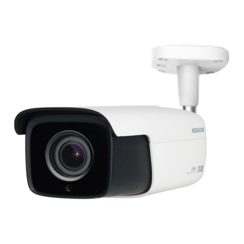
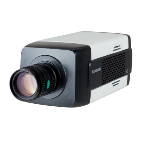
Kedacom IPC981 User manual

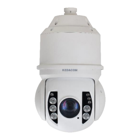
Vehicle Panoramic Speed Dome
Quick Start Guide


Trademarks
® ® ®
, Kedacom , TrueSens , , and NexVision are registered trademarks of
Suzhou Keda Technology Co., Ltd. in China and various other countries. All other trademarks
mentioned in this document are the property of their respective holders.
Suzhou Keda Technology Co., Ltd.
131 Jinshan Road
New District, Suzhou, 215011
People's Republic of China
https://www.kedacom.com
Tel: +86-512-68418188
Fax: +86-512-68412699
© 2020 Suzhou Keda Technology Co., Ltd. All rights reserved.
Without the prior written permission of Suzhou Keda Technology Co., Ltd., any reproduction,
translation or retransmission of all or any part of this document for any purpose in either
electronic or mechanical form is not allowed.
Notice
The information in this document is subject to change without notice. Every effort has been
made in the preparation of this document to ensure accuracy of the contents, but all
statements, information, and recommendations in this document do not constitute a warranty
of any kind, express or implied. Suzhou Keda Technology Co., Ltd. is not responsible for
printing or clerical errors.

I Preface
II Safety Instruction
These instructions are intended to ensure that the user can use the product correctly to avoid danger or
property loss. Please read this Guide carefully before using the product, and keep it properly for future
reference. If the product cannot work normally or is damaged because the user does not follow the safety
instructions, we shall not assume any responsibility. Thanks for your cooperation.
Thank you for purchasing our product. If there is any question, please do not hesitate to contact us.
1. Power Supply
2. Operating Environment
1
Please install an easy-to-use breaker during installation and wiring in case it is necessary to make an
emergency break.
During installing and using the device, please follow local electrical safety regulations strictly.
Please use power supply falling in the safe voltage range of the device. Check if power supply is proper
before running the device.
Please prevent the power cord from being trampled or pressed especially the plug, socket and the
connecting part led out from the device.
Please connect to networks or power supply when the device is powered off. Hot-line wiring is not allowed.
Do not focus the camera lens on strong light such as the sun or incandescent lamp; otherwise the strong
light will cause overexposure or light leak (not camera malfunction), which may shorten the device life.
Please use the power adapter that comes with the device. Using an improper power adapter may cause
damage to the device.
When shipping, storing and installing the device, try to prevent it from damages caused by pressure, violent
vibration and soaking.
To avoid heat accumulation, please do not block the air vent around the device.
Keep the device away from water or any liquid to avoid damage to internal components.
Please transport, use and store the device within defined humidity and temperature ranges.
Do not expose the device in damp, dusty, extremely hot or cold places or places with intense
electromagnetic radiation or with unstable lighting.
Do not install the device on unstable bracket, wall or roof. Otherwise damage or injury may be caused to the
device or people.
While shipping the device, pack it in the factory packing or use materials of equivalent quality.

2
Working Environment
Power Supply
Power consumption: ≤ 40 W
Power: DC 9-36 V
Environment
Waterproof, lightning protection, and anti-interference
Temperature and
Humidity
Temperature
-40 °C ~ +70°C
Humidity
10%~95% ((non-condensing))
3. Daily Maintenance
If the product does not work properly, please contact your dealer or the nearest service center.
problems caused by unauthorized repair or maintenance.
Do not disassemble or repair the device in any way by yourself. We shall not assume any responsibility for
Never apply any organic solvent with ethanol or benzene to clean the lens and housing.
hard to clean, dip some lens cleanser and wipe gently and rotate outward from the center until it is clean.
When the lens is contaminated by dust or grease, use cotton cloth or lens clean cloth to wipe it off. When it is
Do not touch the hot parts of the device to avoid burns.
4. Special Statement
For the updated guide, please go to https://www.kedacom.com/en/downs/index.jhtml.
This guide applies to multiple models but not every model's detailed instructions will be given. You can use
this guide for reference.
When the device is connected to external networks, you should ensure that the device is protected against
malicious network attacks and viruses. We are not responsible for device problems (for example, device
malfunctioning and information leakage) caused by such attacks or viruses.
The device can be used only after being activated through IPCSearch, which can be obtained from
https://www.kedacom.com/en/downs/index.jhtml. During the activation, please fill a valid email address for
re-enabling the default password.
Figures in this guide are for informational purposes only. The actual device appearances should prevail.
A user password must include two or more combinations of digits, case-sensitive letters, and special
characters. Additionally, the password must be 8-16 characters long. The more special characters the
password contains, the stronger the password is. You are advised to use a strong password to ensure your
data safety. Periodically changing your password at 3-month intervals would be appreciated. If your network
environment is risky, you should change your password at weekly or monthly intervals. Additionally, do not
leak your username and password.
5. Special Note
We are not responsible for device damage (even person death) caused by improper driving behavior. You are
advised to comply with traffic regulations and rules when you are driving.

3
III Appearance
Dimensions
412.5
262.5
271.6
140
140
240
φ230
4*φ9
Unit: mm
Weight: 7.5 kg
6. Height Warning
The device is 412.5 mm high. When driving a vehicle with the device loaded into height-restricted places or
on height-restricted roads, you must ensure that the total height of the vehicle and device is 2-2.2 m lower
than the upper height limit.
If a vehicle height bar is lower than usual or there are pipes or other types of blocks on top, you must drive
carefully to prevent impacts on the device.
The preceding warning is especially important for high vehicles, such as SUVs.
【NOTE】

4
Components
IR light
Tilting part Close-up lens
Panning part
Fixed-focus lens*6
Car mount
Installation
direction marker
Installation hole*4
Safety rope
Buttcock lines External Wi-Fi antenna*2
SIM card
The device also has internal Wi-Fi antennas, which can be used only when the preceding parameter
is set to Internal.
The external Wi-Fi antennas come with the device and they can be used only when the Wi-Fi Antenna
parameter is set to the External value on the NVR Web (Settings > Network > IP and Port > Wi-Fi).
The default value is External.
TF card
【NOTE】

Buttcock Lines
The buttcock lines have a female aviation plug on one end.
RJ-45
network
port
RS-485
LINE_IN
LINE_OUT
CAR_ACC
CAR_ON
Power+
Power-
5
No.
Label
Color
Description
1
RJ-45 network
port
-
RJ-45 network port, supporting 10/100/100 Mbps adaptive
2
RS485 A
-
RS-485 serial port A, used to communicate with third-party devices
3
RS485 B
-
4
CAR_ACC
Red
Used to connect to the ACC in the fuse box of the car
5
CAR_ON
Black
Used to connect to the ON in the fuse box of the car
6
LINE_IN
-
Audio input, used to connect to an audio input, such as a handheld
speakerµphone
7
LINE_OUT
-
Audio output, used to connect to an audio output
8
Power+
white
Red+
Power input, used to connect to the anode of the vehicle battery
9
Power-
blue
Black+
Power input, used to connect to the cathode of the vehicle battery

6
Buttcock Line Connection
To connect the female aviation plug to the device:
1) Twist the waterproof cap on the connector receptacle.
【NOTE】
2) Connect the female aviation plug to the connector receptacle.
Buttcock lines are 5 m long.
Cathode
Anode
Power cable
【NOTE】If you do not want to mount the device on a vehicle, you should connect the Power + and CAR_ACC
lines to the anode of a power cable and connect the Power - line to the cathode of the power cable, as
shown in the following figure.

7
IV Installation
1. Installing a SIM Card
1) Ensure that the device is powered off.
2) Make sure your SIM card is a Nano SIM card.
3) Unscrew the two screws on the SIM card cover and take off the cover.
4) Locate the upper SIM card slot and get ready a SIM card eject tool.
5) Push the tool into the small hole next to the upper SIM card slot with a little force until the SIM card tray pops
out a little.
6) Pull the SIM card tray out and place the SIM card in the tray.
7) Slide the tray back.
8) Put the SIM card cover back and fasten it with the two screws.
【NOTE】1) The lower SIM card slot is reserved for future use.
2) The SIM card cover protrudes a little. You should place it properly to prevent water seepage.

8
At most two 512 GB TF cards can be installed.
【NOTE】1) Do not lose the sealing ring in the TF card slot. The sealing ring is essential for preventing water
seepage.
2) Hot swapping is not supported.
3) You must format the TF card before you can use it.
2. Installing a TF Card
TF cards. At most two 512 GB TF cards can be installed.
3) Unscrew the two screws on the TF card cover and take off the cover.
4) Locate the TF card slot and slide the TF card into the slot.
5) Put the TF card cover back and fasten it with the two screws.
1) Ensure that the device is powered off.
2) Get ready a TF card.
The recommended card vendors are SONY, Kingston, SanDisk, and Transcend. You can also buy our custom
【NOTE】1) Do not lose the sealing ring in the TF card slot. The sealing ring is essential for preventing water
seepage.
2) Hot swapping is not supported.
3) You must format the TF card before you can use it.

9
Φ8
180
180
Upper installation
holes*4 (M8)
Lower installation
holes*4 (M8)
Shock-absorbing washer:
3. Installing the Device
Preparations:
1) Before mounting the device on a vehicle, users need to prepare a roof rack.
2) Before the installation, check the heights of all the parts to be installed together with the device. This is to
ensure that the device can be installed high enough to prevent the six fixed-focus lenses from being blocked
in sight.
Steps:
Align the four lower installation holes on the shock-absorbing washer with those on the roof rack and fasten
the washer to the roof rack with four short M8 bolts and nuts.
Short M8 bolts are required since more bolts will be inserted into upper installation holes.
The four short M8 bolts should be inserted below the roof rack and four nuts should be tightened over the
bolts.
Stainless steel bolts and nuts are recommended.
1)
Short M8 bolt
Nut
The four short M8 bolts should be inserted below the roof rack.
Four nuts should be tightened over the bolts.

10
Fastening metal belts or
roof rack clamps
Fasten the roof rack to the car roof with fastening metal belts or roof rack clamps.
It is recommended that this step be performed by professionals.
The fastening metal belts or roof rack clamps cannot be extremely tightened. Otherwise, they may be
damaged by great pulling force when you are driving on bumpy roads.
2)
9
Connect buttcock lines to peripheral devices.
3)

11
Install the device onto the roof rack by inserting four M8 bolts through the upper installation holes on the
shock-absorbing washer and tightening four nuts over the bolts.
Note that the arrow on the installation direction marker should face the same direction as the car head.
4)
Loop the safety rope around the roof rack several times and clip the carabiner onto the roof rack.
Refer to the Appendix for wiring, peel off the film on the lenses, and power on the device.
5)
6)
Short M8 bolt
The four short M8 bolts should be inserted below
the upper installation holes.
Nut
Four nuts should be
tightened over the
bolts.

12
V Log In to the NVR Web or vClient
1. Minimum PC Requirements
2. Activation
When using the device for the first time, run the IPCSearch, which will search devices in a LAN automatically
and display a list of device IP addresses, gateways and etc. If the network provides the DHCP service, the
DHCP server will assign an IP address to the device automatically.
The following activation steps are performed on a computer connected to the device using a network cable.
Operating system: Windows 7 or later
Browser: recommended: IE kernel browsers (without IE kernel browsers, some functions may fail.)
Webpage add-on: hard decoded add-on
DirectX: 9.0c
Processor: Intel® Core™ i5-7500 or later
Graphics card: Intel® HD Graphics 630 or later
RAM memory: 8 GB or greater
Batch activation: Select the device in the IPCSearch and click Batch Processing. In the pop-up window,
enter the admin account's password and the email address for re-enabling the default password. Click
Activate and wait for device rebooting.
One-by-one activation: Right-click the device and choose Activate. In the pop-up window, enter a
username, password, and email address for re-enabling the default password. Click Activate and wait for
device rebooting.
Activation on the NVR Web: Change your computer's IP address to enable it to be on the same network
segment as the device. Open an IE kernel browser and enter a valid IP address of the device. In the
displayed dialog box, enter the admin account's password and email address. Click Activate.

13
3. Change the Device IP Address
On the IPCSearch, select the device and click Modify Params to configure network parameters. To assign the
device a static IP address, check Custom device address (Close DHCP) and configure the parameters below.
Before the changes can take effect, you must enter the password of the admin account. After this, the device
will reboot.
【NOTE】You need to activate and use the device through the NVR Web since the device has 6 lenses, which
form 3 channels.
4. Access the Device
Through the NVR Web
1) On the IPCSearch, select the camera and click Login, or double-click the camera; and enter a username
and password.

14
2) After login, download and install the add-on.
You should close your browser during the installation.
3) Re-log in to the NVR Web.
After this, you can view videos.
【NOTE】Options on the NVR Web vary according to the device model. For details about the NVR Web, see the
help guide provided on the NVR Web.

15
Through the vClient
2) Tap on the tablet which comes with the device.
1) On the NVR Web (Settings > Network > IP and Port > Wi-Fi), set Wi-Fi mode to AP Hotspot.
3) Tap Connect to Hotspot and turn on Use WLAN.
Search for the device on the WLAN network list of the tablet.
The SSID format of the device is "device model-serial number". For example, IPC981-T230-
NIR0146205728. You can also go to the NVR Web (Settings > Network > IP and Port > Wi-Fi) to query the
device's SSID.
Access the WLAN network provided by the device.
The default WLAN password is admin123. To change the password, configure the WLAN Password
parameter on the NVR Web (Settings > Network > IP and Port > Wi-Fi).
4)
5)
6) Go back to the vClient and tap Options.
Under Device, turn on Log In, set IP Address to 192.200.1.200 (the default IP address of the device), and
set Port to 80.
7)

16
【NOTE】Some part in the preceding figure is intentionally blurred.
8) Tap OK. And then, go back to the login dialog box, enter a username and a password of an NVR Web
account, and tap LOG IN.
After this, you can view live videos from the device. For more operations, see the user manual of the
vClient.

Appendix Wiring
No.
Name
Description
1
Connector
receptacle
Connect the female aviation plug to the connector receptacle, and twist the
waterproof cap on the connector receptacle to prevent water seepage.
2
Buttcock lines
Connect some buttcock lines to the battery and fuse box of the car.
3
Wi-Fi antennas
(2)
Connect them to the device and stick the other ends to the center console of the
car. The two antennas should be used together.
17
1
2
3
12
3
Table of contents
Other Kedacom Security Camera manuals

Kedacom
Kedacom IPC524 Series User manual

Kedacom
Kedacom IPC2240-HN-SIR30 User manual

Kedacom
Kedacom IPC2860 Series User manual

Kedacom
Kedacom IPC4X2 Series User manual

Kedacom
Kedacom IPC2452-HN-SIR User manual

Kedacom
Kedacom IPC2860-HN-PIR15 User manual

Kedacom
Kedacom IPC4X1 Series User manual

Kedacom
Kedacom IPC425 User manual

Kedacom
Kedacom IPC2255-Gi4N Series User manual

Kedacom
Kedacom IPC52X Series User manual