Kedacom IPC425 User manual

高清红外球型网络摄像机
Network IR Speed Dome Camera
Quick Start Guide
快速安装指南


前言
安全说明
感谢您购买我司产品,如对本公司产品有疑问或需要,请随时和我们联系。我们尽最大努力来保证
本手册信息的正确性,如因升级等原因发生信息修改,恕不另行通知。
获取最新文档请联系产品供应商。
请使用满足安全电压要求的电源。
如果设备工作不正常,请联系厂家或最近的服务中心。不要以任何方式随意拆卸或修改设备。
请勿将任何物品摔落到设备上或强烈敲击设备。
清洁镜头时,须使用吹气球或专业镜头布除去镜头上的污垢。清洁透明球罩时,须使用足够柔
软、干燥的布擦拭,切勿使用含酒精、苯等清洁剂洗涤。
避免将摄像机对准强光(如灯光照明、太阳光等处)聚焦,否则容易引起过亮或漏光现象 (这并
非摄像机故障) 也将影响摄像机寿命。
避免将产品暴露在非用户手册所示的工作环境下使用 。
使用时不可让水或任何液体流入摄像机。
当运送摄像机时,请重新以出厂时的包装进行包装,或用同等品质的材质包装。
需要替换部件时,请事先与经销商联系,更换指定型号的部件,或与原部件具有相同特性的部
件。擅自使用其它部件进行替换,后果自负。
此手册的目的是确保用户正确使用本产品,以避免危险或财产损失。在使用产品之前,请认阅读此
手册并妥善保存以备日后参考。如果用户因没有按照以下安全说明,致使设备不能正常使用或损坏
等情况,责任由用户承担。
安装环境
供电要求
AC24V±10%
环境要求
防水、防干扰、防雷击
温湿度
工作温度
-40℃~70℃
工作湿度
10%~95%(相对、无凝结)
1
防水
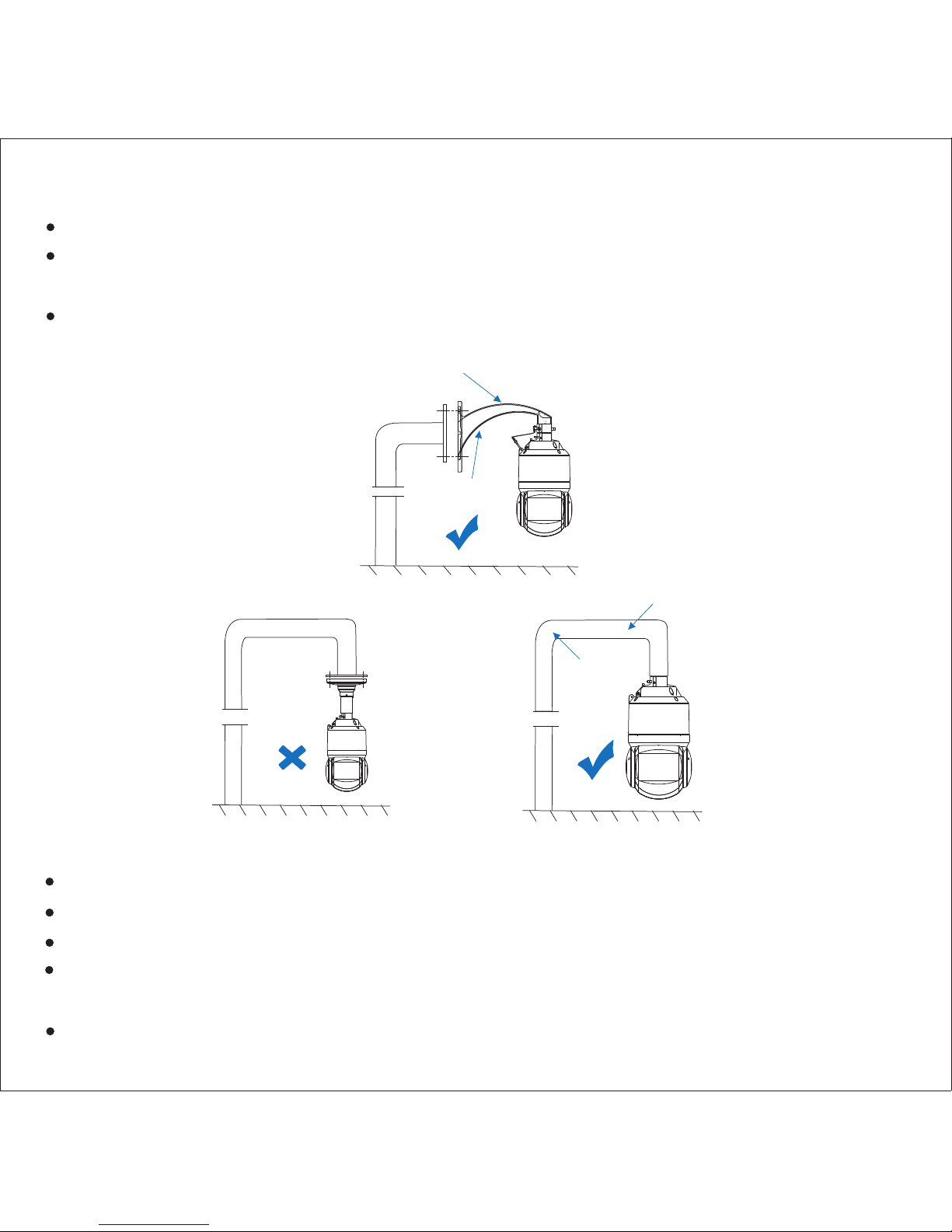
室外安装推荐使用支架横臂有一定向上角度的壁装支架。
用户自选支架安装推荐使用连接口为内螺纹的支架,同时须确保支架的防水性能;用户自选支
架安装若选用外螺纹支架,须确保支架与球机连接的转接器件的防水性能。
安装时螺纹口需缠绕生料带,并确保螺纹密封;安装时对准螺纹,不能出现明显偏位及滑丝。
防静电、防干扰、防雷、防浪涌
IPC安装不进行接地可能会因为静电造成电子器件损坏。
在雷电多发地区,需要对IPC进行就近接地,释放雷击等高能量,防止IPC损坏。
在电压不稳地区,需要对IPC进行接地,释放浪涌等高能量,防止IPC电源烧坏。
IPC安装防雷接地线不能替代安全接地线。在采用接地不良的立杆,如木杆、水泥杆,需要安
装安全接地线,泄放漏电流以确保IPC或立杆不引起安全事故。
IPC安装防雷接地线不能借用附近的其他电子设备接地线入大地,必须单独接地。
横臂上有一定
向上角度
横臂上不能有开口或裂纹
横臂上不能有
开口或裂纹
一体成型的
横臂和立杆
2

水泥杆方式需要配置钢管护套用于接地线穿管,如图所示,球机接地线从钢管内部穿过接地。控制
中心本地进行规范接地即可。
【水泥杆接地】
金属杆方式采取PVC管穿接地线。没有安装避雷针的金属立杆,采用接地线(穿PVC管套)靠近金
属杆的位置固定后实施接地,如图所示。
【金属杆接地】
接地导线电阻≤4Ω
水泥杆接地
钢管保护套
打入地下1.5米 打入地下1.5米
MUTE
USB USB
LAN ALM PWR
显示器
键盘
NVR/监控平台
UPS
接地柱
接地柱
接地柱
工作台接地柱
控制中心
水泥杆
金属杆接地
PVC管套
打入地下1.5米
接地导线电阻≤4Ω
打入地下1.5米
MUTE
USB USB
LAN ALM PWR
显示器
键盘
NVR/监控平台
UPS
接地柱
接地柱
接地柱
工作台接地柱
控制中心
金属杆
3
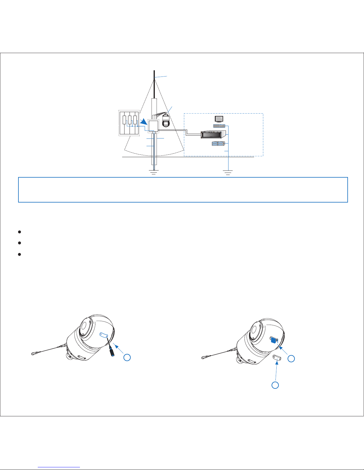
【注意】如果IPC传输过程中使用了光端机或者防雷器等中间件,需确保中间件接地良好,同时
需确保IPC的连接线缆通过中间件也能接地良好。
PVC管套
避雷针
打入地下1.5米
接地导线电阻≤4Ω
视频 避雷 器
通讯 避雷 器
电源 避雷 器
金属杆
打入地下1.5米
MUTE
USB USB
LAN ALM PWR
显示器
键盘
NVR
/监控平台
UPS
接地柱
接地柱
接地柱
工作台接地柱
控制中心
球机必须安装
在避雷针下45°
的范围内
安装检查
墙壁/天花板厚度可支持安装膨胀螺钉。
墙壁/天花板可承受8倍球机加支架等附件的总重量(球机最大净重:6.1Kg)。
安装前请留出足够安装空间(球机高度:376mm;球机直径:Ø202mm)。
安装球机前,须对安装墙面/天花板进行安装强度检查。
安装存储卡
球机安装
在球机球型结构上打开扣盖,安装存储卡,最高可支持32G容量存储卡。
1拧松扣盖上两颗螺钉,
取下扣盖
2插入存储卡
3安装扣盖
【说明】存储卡安装位置以具体设备上所贴标签为准。
4

将线缆从支架穿出,线缆请留出足够长度,以便连接到球机内线缆(推荐预留20cm~30cm)。
根据安装贴纸在墙面打好孔并塞入膨胀螺钉,将支架底座的孔对准墙面上的孔,放入螺钉,锁紧。
1.
2.
支架底座出线
1钳开出线孔
B
支架底座
壁装支架安装
4
2
3向下布线,注意防水
墙面
膨胀螺钉
20~30cm
固定支架
穿出线缆
1穿出线缆
2向下布线,注意防水
3
墙面
膨胀螺钉
固定支架
20~30cm
穿墙出线
缠生料带
连接转接件
锁紧螺钉
1
2
3
3. 在转接件螺纹处缠上生料带,将转接件旋紧到安装支架上,锁紧支架上的螺钉,并确认转接件上防
脱螺钉处于非锁紧状态;取出安全挂钩,将一端预先挂扣在转接件的挂耳上。
5
挂扣安全挂钩
4非锁紧状态
转接件规格: 1
2
1
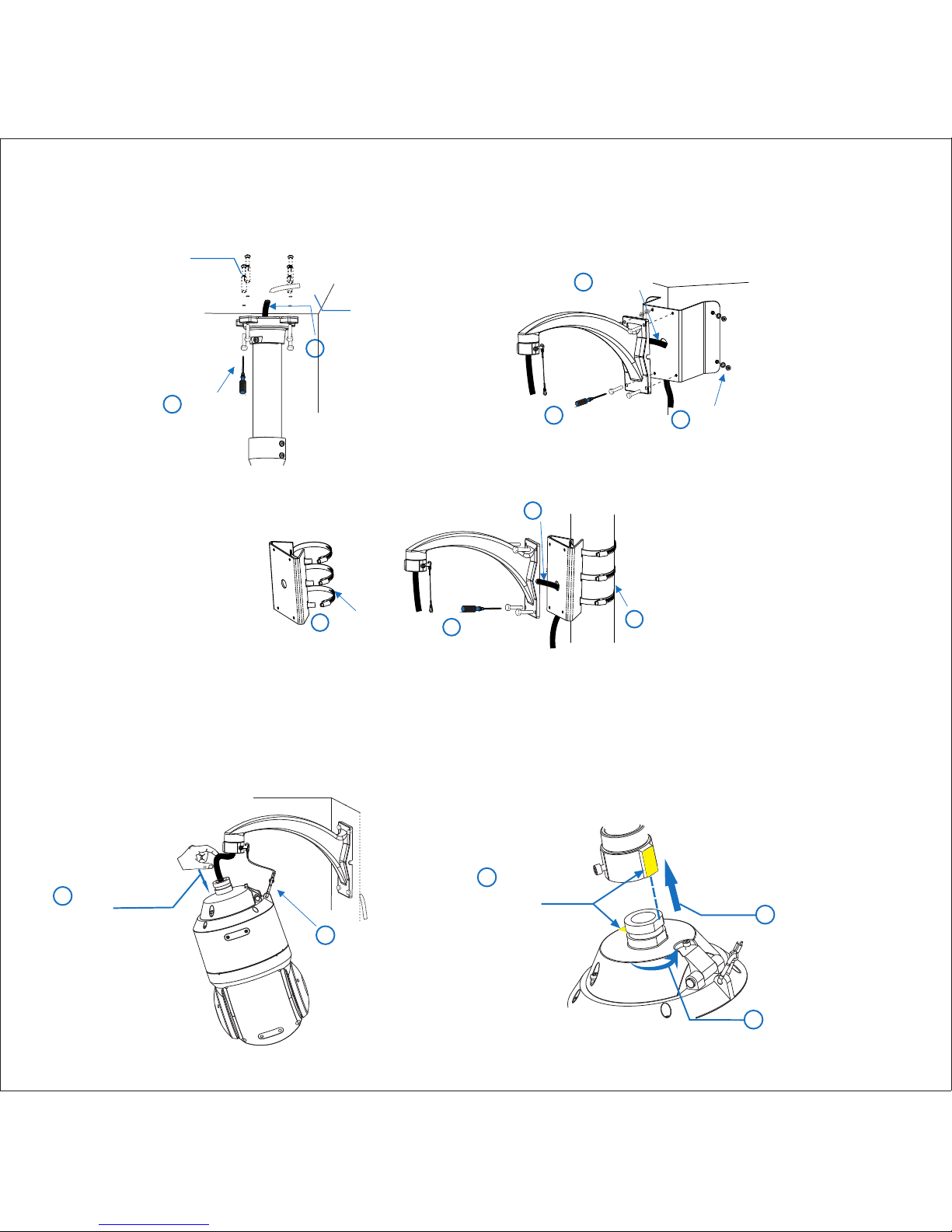
其他支架安装
装配转接件步骤参照壁装支架。
【说明】支架均为选配配件。
1
2固定支架
穿出线缆
墙面
膨胀螺钉
吊装支架安装
2
3固定支架
1
固定墙角装支架
穿出线缆
墙角支架安装
抱柱支架安装
固定
抱柱装支架
穿出线缆
1
2
3
4固定支架
旋开卡箍
球机安装
先将支架上的安全挂钩另一端挂扣到球机上,线缆穿过上球罩;球机安装柄的D字直边对准转接件
上的标签后,将球机上推进转接件底部并旋转180°至黄色标签对齐,此时球机已固定。
1.
2
1
线缆穿过上球罩
挂扣安全挂钩
3D字直边对准转接件
上黄色标签直边后推
至底部
4顺时针或逆时针180°
旋转上球罩
6
5对齐黄色标签,
固定球机
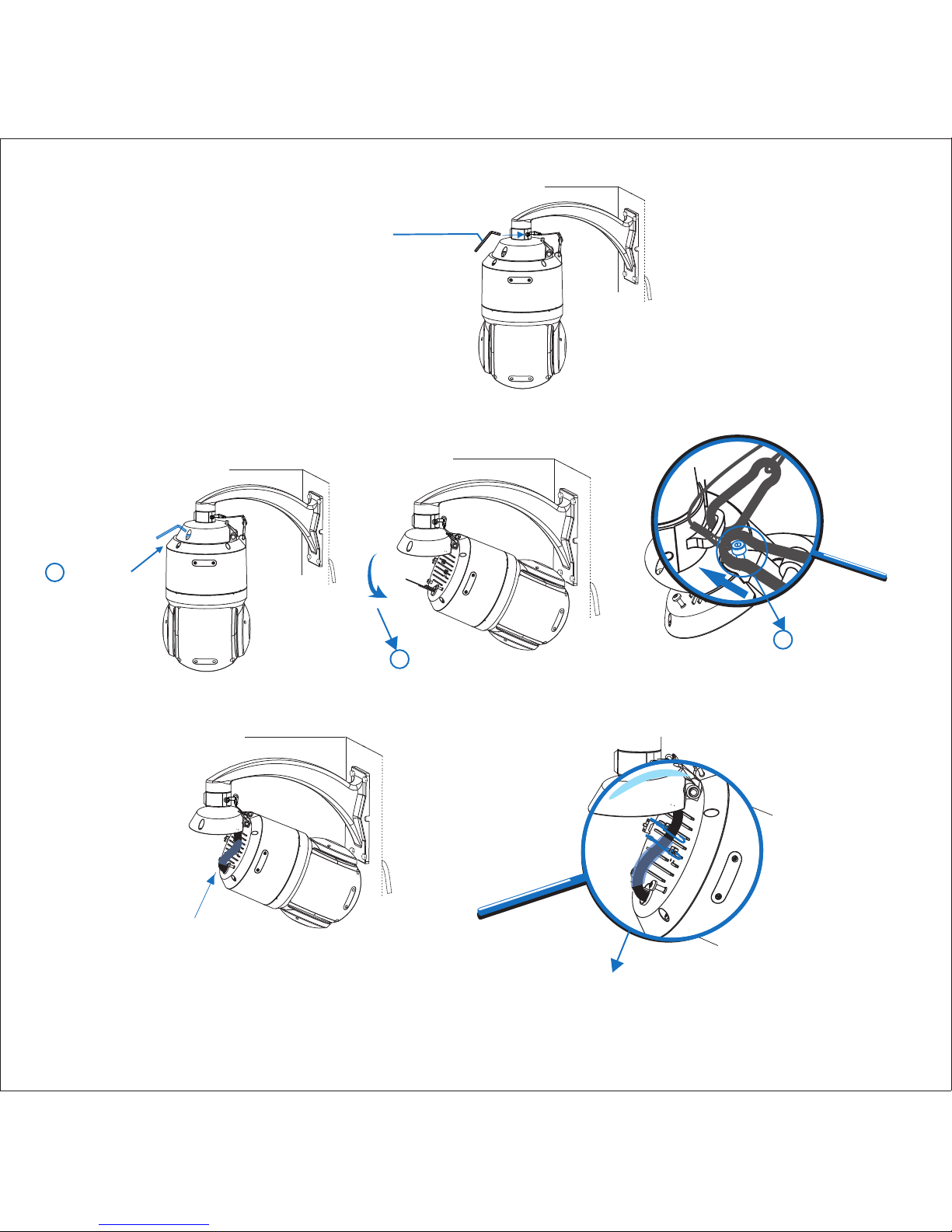
锁紧转接件上的两颗防脱螺钉。2.
按照球罩内所贴标签连接线缆,线缆连接见附录,连接完成后检查并整理各类线缆,线缆接口处用
绝缘胶布缠绕牢固,务必将线缆整理好并用束带捆绑住,束带穿过束带固定件并拉紧束带。
4.
摘下挂扣在上球罩螺钉上的安全挂钩,盖扣上球罩并拧紧上球罩上两颗固定螺钉。5.
拧开上球罩上两颗固定螺钉,打开上球罩,并将挂扣在上球罩上的安全挂钩小孔端挂扣在上球罩凸
起的螺钉上。
3.
锁紧防脱螺钉
3将安全挂钩小孔
挂扣在螺钉上
7
1旋开螺钉
2打开上球罩
连接线缆
并用绝缘胶布缠牢
固定线缆

安装完成后,请再次检查,确保球体密封。
设备上电,并使用IPCSearch进行初始配置和登录。
设备上电
附录
外设连接示意图
LAN
客户端
网口
连接监控键盘或告警扩展器等
剪短端子台连线
根据线缆标签连接相应设备 RS485
告警输入
音频输入
音频输出
告警输出
KEDACOM
AC24V 电源
KEDACO M
KEDACOM
KEDACOM
【说明】具体线缆连接以实际设备上所贴线缆标签为准。
8
Other manuals for IPC425
1
Table of contents
Other Kedacom Security Camera manuals

Kedacom
Kedacom IPC Series User manual

Kedacom
Kedacom IPC2255-Gi4N Series User manual

Kedacom
Kedacom IPC425 User manual

Kedacom
Kedacom IPC2240-HN-SIR30 User manual

Kedacom
Kedacom IPC2251-AN User manual

Kedacom
Kedacom IPC524 Series User manual

Kedacom
Kedacom IPC427-D120-N User manual

Kedacom
Kedacom IPC52X Series User manual

Kedacom
Kedacom IPC2860-HN-PIR15 User manual

Kedacom
Kedacom IPC4X1 Series User manual


