4
1. Measuring Principles and Features
■ Measuringprinciple
■ Features
● Thecalibrationcurvememoryfunctionisintegrated.
Up to 50 types can be calibrated and stored as an application for each probe. Thanks
to this function, the measurement can be performed without troublesome calibration
from the second time at the same measurement. A memorized application will not be
erased even if the power is switched off.
● Satisfactorilydiversiedfunctionsareprovidedasacoatingthicknessgauge.
Various settings such as auto power-off function, backlight setting, upper/lower limit
setting function, and statistics function are available.
● Datacanbeoutputtedtotheprinter.
Measured values, statistical calculation results, and more can be printed with the built-
in printer.
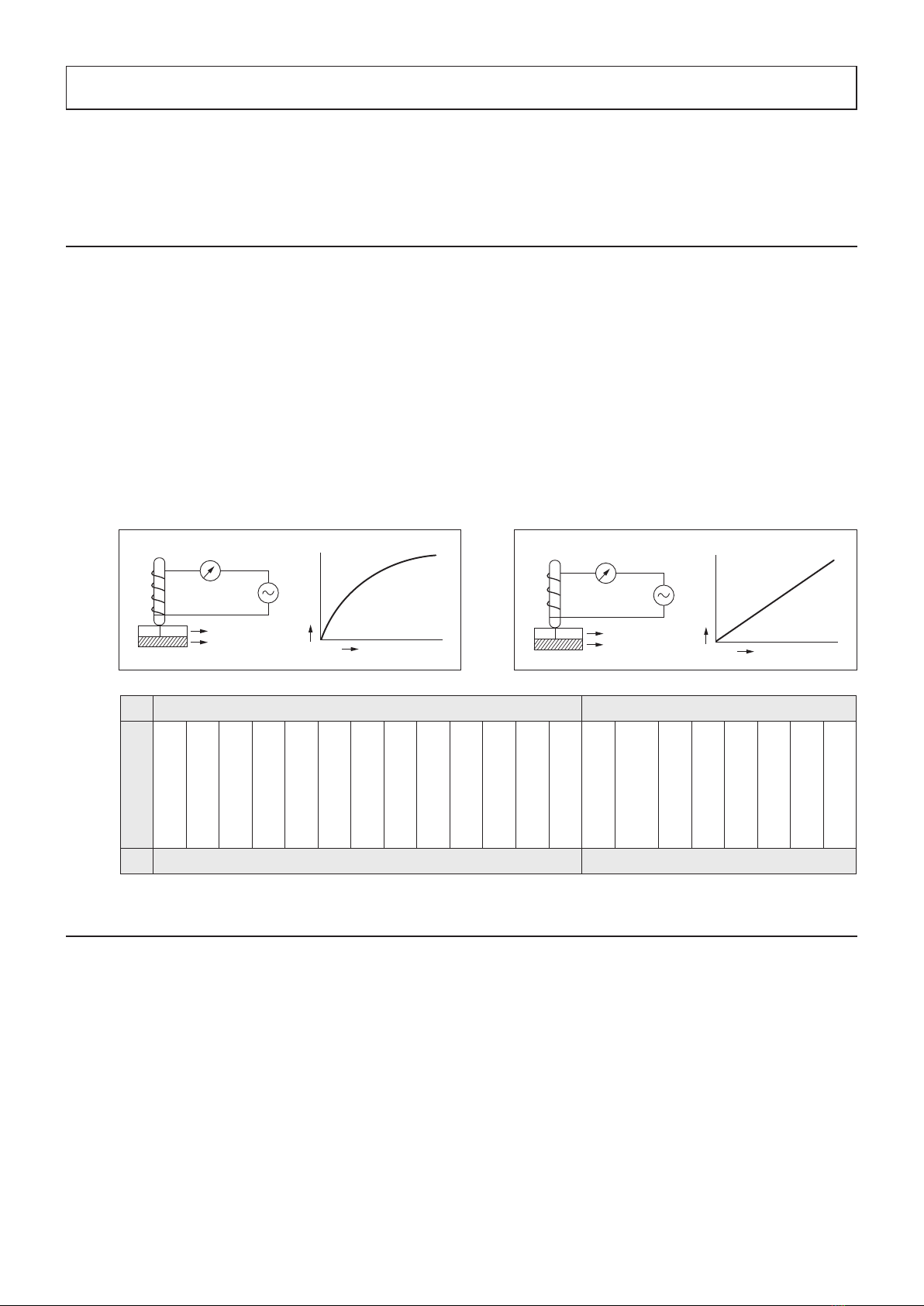
Electromagnetic type (Fe probe) Eddy current type (NFe probe)
Coating to be measured
Paint
Plastic
Lacquer
Resin
Rubber
Enamel
Lining
Zinc
Chrome
Tin
Copper
Aluminum
Other
Paint
(Anodic oxide coating)
Alumite
Rubber
Plastic
Enamel
Lacquer
Resin
Other
Substrate
Iron/steel Aluminum, Copper, Brass, etc.
● Electromagnetictype(Feprobe)
Measurement of non-magnetic coatings on
magnetic metals
If an electromagnetic coil through which a constant
low-frequency current flows is brought into the
proximity of iron (magnetic metal), the number of
magnetic ux lines through the coil varies with the
approaching distance, which causes the variation of
voltage between the ends of the coil. This change
in voltage is detected by the current value and is
calculated in terms of coating thickness.
The Coating Thickness Tester L-500 is a coating thickness gauge that can measure in both
electromagnetic type and eddy current type depending on the probe to be connected.
Non-magnetic coating
D
Thickness D
lron/steel
Electromagnetic coil
i
Low-frequency power supply
i
Current change
Insulating coating
D
Thickness D
Non-ferrous metal
Induction coil
i
High-frequency power supply
i
Current change
● Eddycurrenttype(NFeprobe)
Measurement of insulating coating on non-magnetic
metals
If an induction coil through which a constant high-
frequency current ows is brought into the proximity
of a metal, eddy currents are generated on the
surface of the metal. Then these eddy currents
uctuate according to the distance between the coil
and the metal surface and thus changes the voltage
on each end of the coil. This change in voltage is
detected by the current value and is calculated in
terms of coating thickness.