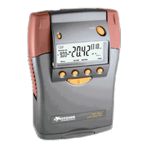
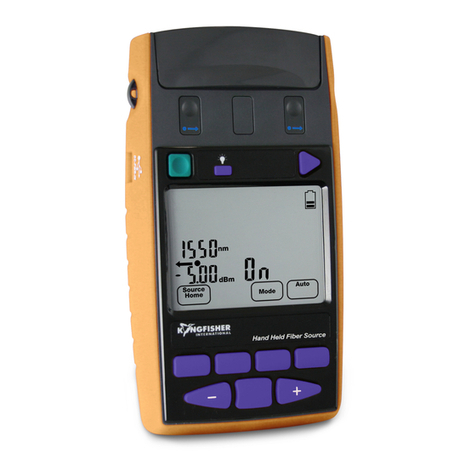
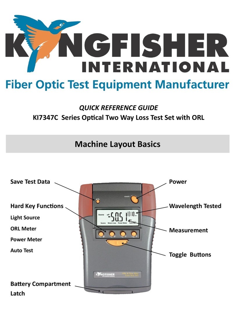
Kingfisher KI2000 Series Operating manual

OPERATION & MAINTENANCE GUIDE
Two Way Test Set + ORL
Two Way Loss Test Set
KI 23400 Series
KI 27400 Series

DECLARATION OF CONFORMITY
IN ACCORDANCE WITH ISO/IEC 17050:2004
Manufacturer’s Name: Kingfisher International Pty. Ltd.
Manufacturer’s Address: 720 Springvale Road, Mulgrave, Victoria 3170, Australia
hereby declares, that the products listed below
Product Name: Optical Power Meter, Optical Light Source, Optical Loss Test Set
Model Number: KI2000 Series
Product Options: This declaration covers all options of the above product(s)
complies with the essential requirements of the applicable European Directives:
•Low Voltage Directive 2014/35/UE and the EMC Directive 2014/30/UE, and carries the CE marking accordingly
•Directive 2011/65/EU on restriction of the use of certain hazardous substances in electrical and electronic equipment (RoHS)
•Directive 2012/19/EU on waste electrical and electronic equipment (WEEE). The instrument can be disposed of local retail shop with
WEEE collection point.
and conform to the following standards and specifications:
MIL-PRF-28800F:1996 Performance specification -Test equipment for use with electrical and electronic equipment, general specification
IEC 60529 Ed. 2.2 / EN 60529:1991 Degrees of protection provided by enclosures
Power Meter conforms to:
IEC 61315 Ed. 2.0 Calibration of fibre-optic power meters
EMC Limit
IEC 61326-1 Ed. 2.0 / EN 61326-1:2013
IEC CISPR 11 Ed. 6.1 / EN 55011:2016 Limits applicable to Group 1 Class B equipment
IEC CISPR 16-1:2004~2019 Limits applicable to Class B equipment
IEC CISPR 16-2:2003~2016 Limits applicable to Class B equipment
IEC 61000-3-2 Ed. 5.0 (2018) / EN 61000-3-2:2014
IEC 61000-3-3 Ed. 3.1(2017) / EN 61000-3-3:2013
IEC 61000-4-2 Ed. 2.0 (2008) / EN 61000-4-2:2009 4kV CD, 8kV AD
IEC 61000-4-3 Ed. 3.2 / EN 61000-4-3:2006 3V/m, 80-1000MHz
IEC 61000-4-4 Ed. 3.0 / EN 61000-4-4:2012 1kV signal lines, 2kV power lines
IEC 61000-4-5Ed. 3.1 / EN 61000-4-5:2014 1kV line-line, 2kV line-ground
IEC 61000-4-6 Ed. 4.0 / EN 61000-4-6:2014 3V, 0.15-80 MHz
IEC 61000-4-11 Ed. 2.1 / EN 61000-4-11:2004 0.5 cycle/100%/each polarity
ICES-001: 2006 (Canada)
CFR 47 FCC Part 15, Subpart B (Exempted devices) (USA)
Safety
Light Source conforms to:
IEC 60825-1:2014 Safety of laser products - Equipment classification, requirements and user’s guide
IEC 60825-2:2004 Safety of laser products - Safety of optical fibre communication systems (OFCS)
CFR 21part 1040.10 (USA) Performance standards for light- emitting products-Laser products
Supplemental Information:
The product was tested in a typical configuration with Kingfisher International test systems.
17 March 2020
Date
Bruce Robertson
Name
Technical Director
Title
Revision: F Issue Date: 17 March 2020

OPERATION MANUAL
KI23400/KI27400 UM-2
- 1 -
KI234xx Premium Two-Way Optical Loss Test Set
with Length & Optical Return Loss (ORL)
KI274xx Two-Way Optical Loss Test Set with
Length
Congratulations on your purchase of this equipment, engineered to provide
excellent performance, convenience, and reliability. To get the best use
from your instrument and to ensure its safe operation, please spend a few
minutes to read this manual.
Made in Australia. International
© Copyright Kingfisher International Pty Ltd
Edition 2, Sep 2020

CONTENTS
KI23400/KI27400 UM-2
- 2 -
Contents
Contents..........................................................................2
Pictures of Instrument.....................................................5
Applications Support.......................................................7
Instrument Service..........................................................7
Introduction and Applications..........................................8
Typical Test Applications (all options):................................ 8
Key Benefits........................................................................ 8
Memory and External Software Features............................ 9
Autotest Two-Way Loss, ORL & Length.............................. 9
ORL Meter Features ......................................................... 10
Power Meter Features....................................................... 10
Light Source Features....................................................... 11
Multi-Fiber ID, Continuity & Locator Features................... 11
Test Standards Compliance..........................................12
General Safety Summary..............................................13
Initial Inspection ................................................................ 13
Operating Environment..................................................... 14
Storage & Shipment Environment..................................... 14
Mains Voltage Safety........................................................ 14
Laser Eye Safety Information............................................ 14
Battery & External Power..............................................16
Disabling Battery Charging ............................................... 16
Enabling Battery Charging................................................ 16
Push-On Optical Connector..........................................19
Power Meter...................................................................... 19
Light Source...................................................................... 20
How To Clean Optical Connectors.................................... 20
When To Clean The Optical Connectors........................... 21
Screw-On Optical Connector........................................22
How To Clean The Optical Connectors............................. 22
Getting Started & Turning On .......................................24
Turn On The Instrument.................................................... 24
Backlight ........................................................................... 25
Operation.......................................................................... 25
Fiber Optic Connector Arrangement ................................. 25
Basic Power Meter............................................................ 25
Basic Light Source............................................................ 26
Application Software ......................................................... 26
Firmware upgrade............................................................. 26
Instrument Hard Re-start................................................... 26
Setting Time & Date......................................................27
Menu Navigation Tips...................................................28
LCD General Information.................................................. 28
Autotest Overview.........................................................29
Two-Way Autotest............................................................. 29
One-Way Autotest............................................................. 29
Limiting Active Autotest Options ....................................... 29
Autotest Data saved.......................................................... 30
Autotest General Operation .............................................. 30
Autotest Operation............................................................ 31
Kingfisher Autotest Compatibility....................................... 31
Autotest Two-Way Operation........................................32

CONTENTS
KI23400/KI27400 UM-2
- 3 -
Two-Way Referencing....................................................... 32
Length Measurement........................................................ 33
Autotest One-Way Operation........................................34
One-Way Referencing....................................................... 34
Autotest User-To-User Communication........................35
Autotest λRestriction ....................................................36
Method 1 (easy)................................................................ 36
Method 2 (more control).................................................... 36
A Test Lead Verification Test Procedure......................37
Pass / Fail Testing ........................................................39
Pass/Fail Set Up ............................................................... 39
Pass/Fail Operation........................................................... 40
Continuity & Polarity Test Overview .............................41
VFL-VisiTester Option....................................................... 41
Standard Test Tone Source & Detection........................... 41
Advanced Test Tone Source & Detection......................... 41
Power Meter Manual Operation....................................42
Light Source Manual Operation....................................43
ORL Meter Manual Operation.......................................44
Low Reflection Terminations............................................. 44
ORL Meter Operation........................................................ 44
ORL Zero Function............................................................ 44
User Calibration Mode (UCAL) ......................................... 45
VFL-VisiTester Operation .............................................46
Tone Detection & Slow Mode .......................................47
Test Recording & Reporting Overview .........................48
Instrument Memory Overview.......................................49
Instrument Memory Operation......................................50
Recording Data to Memory............................................... 50
Recalling Stored Data from Memory................................. 50
Re-Test or Over-Write Results.......................................... 51
Clearing Memory............................................................... 51
Memory Capacity.............................................................. 51
Instrument USB Ports ....................................................... 52
Text ID Tag Operation ..................................................53
Use a Stored Text ID Tag ................................................. 53
Modify a Text ID Tag......................................................... 53
Delete a Text ID Tag......................................................... 53
Create a New Text ID Tag ................................................ 53
Application of TEXT ID Tag............................................... 54
USB Key Memory Dump...............................................55
Instrument Data Sanitization.........................................55
External KITS™ Software .............................................56
Instrument Firmware Updates........................................... 56
Tier 1 Test Example......................................................57
Care of Your Instrument................................................60
Accuracy Considerations..............................................61
Power Meter...................................................................... 61
Light Source...................................................................... 62
Optical Return Loss........................................................... 62
DWDM Loss & Power Measurements............................... 62
CWDM Loss & Power Measurements............................... 62
Definition Of Terms.......................................................64
Specifications................................................................65

CONTENTS
KI23400/KI27400 UM-2
- 4 -
Ordering Information.....................................................70
Calibration & Maintenance............................................73
Performance Verification Tests.....................................75
Power Meter...................................................................... 76
Light Source...................................................................... 76
Two Way Autotest............................................................. 78
One Way Autotest............................................................. 80
Length measurement........................................................ 81
Optical Return Loss........................................................... 81
Required Equipment ......................................................... 84
General Test Records....................................................... 85
Quick Reference Guide.................................................92
Disclaimer & Warranty..................................................98
Notes.............................................................................99

KI23400/KI27400 UM-2
- 5 -
Pictures of Instrument
KI23400 / 27400 HANDHELD 2-WAY LOSS TEST METER
Toggle Centre
Memory USB
store
On/Off
Display
Backlight
Battery
compartment
Connector release
& port identifier
Lugs for
Carry Strap
Flip-over connector
cover & tilt bail
Labelling:
Compliance
Model No
Basic Operation
Anti-slip strip

KI23400/KI27400 UM-2
- 6 -
KI23400 / 27400 HANDHELD 2-WAY LOSS TEST METER
Micro USB port for
data and power
USB port for
memory stick
Full-segment picture of LCD
Slim, easy
to hold

SERVICE AND SUPPORT
KI23400/KI27400 UM-2
- 7 -
Applications Support
Please visit www.kingfisherfiber.com to see our comprehensive
Application Notes written to support instrument users, an updated
version of this manual or instrument firmware updates. FAQs can be
found in the “Support” section of our website.
This equipment can perform testing in accordance with TIA and IEC
fiber optic test standards. Please refer to www.kingfisherfiber.com for
details.
Look at www.kingfisherfiber.com to find distributor and service centre
details from the Contact Us section.
Our local agents can offer excellent applications advice in your
language and time zone.
If you are having difficulties, please feel free to contact
Instrument Service
Qualified personnel must perform adjustment, maintenance, or repair
of this product. Refer to General Safety Summary section of this
manual. To obtain service, please contact your local Kingfisher
International distributor or our office in Australia:
Tel: (+61) 3-8544-1700
Fax: (+61) 3-8544-1793
Email: sales@kingfisher.com.au
If returning equipment to us for service or calibration, please download
and complete the Return Material Authorization Form located on
the Support page on our web site.
To avoid delays and minimise disruption for our customers, we offer a
fixed price repair service.
For the staff at our fully equipped service and calibration centre, it is
their pleasure to keep your equipment performing at its very best.

INTRODUCTION AND APPLICATIONS
KI23400/KI27400 UM-2
- 8 -
Introduction and Applications
The KI2000 family of Two-Way Optical Loss Test Sets are used to test
single mode and multimode fiber optic cable & systems, including for
high throughput Tier 1 certification, with exceptional convenience,
productivity, and accuracy. These instruments are compact, robust,
and reliable, and are ideal for use by installers, technicians or
engineers in field and laboratory situations.
The instruments are simple to operate, with convenient menus to
guide the user through operational sequences. The large, sunlight
readable custom LCD is an exceptional feature, with a wide viewing
angle and backlight. With simple operation and visual appearance,
these meters offer a surprising level of integrated functionality.
Excellent test accuracy is achieved, while the zero warm up source
options provide exceptional source stability for demanding test
situations.
The innovative VFL VisiTester option is particularly helpful in high fiber
count environments, particularly to locate the exact fiber to be tested.
The interchangeable optical connectors are easily dis-assembled for
cleaning. They are protected by a dust cover, which also flips over to
serve as a handy instrument tilt bail. Many connector styles are
available.
The tough housing has shock-absorbing rubber corners for drop
protection. The latest materials and methods are used to produce an
elegant, yet rugged instrument.
Battery life is 80 –1000 hours from 2 x AA alkaline or NiMH cells.
Instruments can be externally powered or charged via micro USB.
Typical Test Applications (all options):
•Instrument Pair and Two-Way Autotest: Two-way loss, ORL &
length with pass/fail, ideal for Tier 1 Certification.
•Stand-alone instrument and One-Way Autotest: One-way loss,
basic light source, power meter and ORL tester.
•Max / Min power stability testing
•Test reporting & data logging with data security in MS Excel
with KITS™ software
•MPO capable power meter with interchangeable connectors
•Continuity & polarity check using test tones & VFL-VisiTester
•Tone source for fiber identifiers
•Single mode, multimode, mixed, and custom fiber options
Key Benefits
✓Complete network certification & reporting
✓Optimise productivity and minimise training
✓Excellent test accuracy and flexibility
✓Minimise false rework with simple one hook-up test method

INTRODUCTION AND APPLICATIONS
KI23400/KI27400 UM-2
- 9 -
With just one button push and high accuracy, a single fiber connected
between two instruments can test & pass / fail at several wavelengths
based on: Bi-directional loss, ORL each end, and cable length.
Autotest communicates test data between instruments to automate
loss testing and share results. Test parameters are pre-configurable,
to minimise test time and skill.
Pass/fail test & reporting parameters are flexible and can match latest
standards.
These instruments supersede the functions and specifications of our
popular KI7000 series Two-Way testers.
Memory and External Software Features
There are 3 ways of saving test data and reporting:
1. Test & Report in real time, with one click on a connected
computer. Each cable test result is shown immediately on the
KITS™ Excel pass/fail report. In this mode, instrument operation
is remotely controlled from the attached computer.
2. Results can be stored in the instrument’s large non-volatile
memory along with text-input cable name and timestamp, then
downloaded later onto a computer with the secure KITS™
reporting software.
3. Results can be stored in the instrument’s large non-volatile
memory along with text-input cable name and timestamp, and
then a csv file is exported onto a USB memory stick (or a phone
micro SD card using a suitable adaptor), via the Type A USB port,
for later analysis on KITS™ or other software. This is a simple
and easy way to store and transmit test data from a site,
independent of any operating system or software.
KITS™ Excel reporting software allows interactive instrument control
and data download. Real time display, data logging and unformatted
data dumps are also included. In addition to two-way testing, KITS™
enables merging of test results from multiple one-way instruments and
so supports bi-directional testing for one-way equipment using
successive measurements.
Test data security is applied to all input and output data files, and
KITS™ is designed to prevent data tampering when in Secure Data
mode. This balances the conflicting requirements of data security, and
user flexibility. Retained original data files can be accessed later as an
audit function.
The KITS™ software data logging feature updates the data file
continuously, so that in the event of a power cut or other computer
malfunction, the acquired test data is secured. This is essential for
long term integrity or environmental testing, for example.
Autotest Two-Way Loss, ORL & Length
This mode is the easiest, fastest and most complete test method for
most applications. It requires a pair of instruments to operate.

INTRODUCTION AND APPLICATIONS
KI23400/KI27400 UM-2
- 10 -
Test time for Bidirectional Autotest Two-Way Loss, ORL and Length
is typically a few seconds per fiber, with major savings in skill, time,
cleaning materials and test confidence.
Accurate and stable, the real time display in this mode offers genuine
time saving for users, since a poor or unstable fiber hook-up can be
immediately recognized and corrected before saving a measurement.
Both local and remote loss referencing is supported.
A handy Autotest communications feature helps both users step
quickly through a large fiber array. This feature also links through to
real-time acquisition with KITS™ software.
ORL Meter Features
ORL test is an option, depending on instrument p/n.
Full-function ORL testing can be performed as an integrated part of
Two-Way Autotest, or as a stand-alone manual test.
User selectable offset and residual compensation functions greatly
improve accuracy and range and are typically used in component or
bench test applications.
Power Meter Features
The full-function power meter can be used in One-Way Autotest or
manual modes.
Power meter options cover the range +33dBm to -70dBm.
Various detector options include Indium Gallium Arsenide (InGaAs),
Germanium (Ge), Silicon (Si) and high-power versions.
Power meters with standard detectors work with fiber core diameter
up to 200 microns, with both PC and APC polish connectors such as
universal 2.5, 1.25 mm, SC, LC, FC, ST, SMA, MU, LSA, E2000
Power meters with Large Area Detectors work with an active fiber core
diameter up to either 3 mm or 5 mm. Common applications include
ribbon fiber MPO/MTP (all types up to 32 or 72 fibers), CS, MDC, SN
and POF / HCS connectors.
Accurate & fully traceable calibration options cover all popular
application λfrom 635 to 1650 nm and may include CWDM
calibrations from 1270 nm to 1610 nm in 20 nm increments.
Calibration λare all genuine, with no interpolated or inferred calibration
values.
Superior operational accuracy is clearly defined with a unique Total
Uncertainty Specification, which covers the full temperature, dynamic
and connector range.
There is no warmup period, range-changing delay, or user dark
current zeroing.
Power stability testing over a period can be performed using the
max/min recording function.
The display shows dBm, dB mW, µW, nW, to 0.01 dB resolution, and
can be put on hold for convenient manual data recording.

INTRODUCTION AND APPLICATIONS
KI23400/KI27400 UM-2
- 11 -
A separate reference for each λis stored and displayed.
When performing loss testing using an Autotest light source, up to
three λare displayed simultaneously.
Light Source Features
The full-function light source is used as part of Autotest, or as a simple
test source, or for generating test tones. Multiple λsources are
selected through the same port, which makes operation faster.
Laser sources at 1310 / 1490 / 1550 / 1625 nm are used for testing
single mode fiber systems, and LED sources at 850 / 1300 nm are
used for testing multimode fiber systems. Laser power level can be
user adjusted by 6 dB.
KI23400 series include zero warm up, ultra-stable lasers. These
sources use an unusual architecture to achieve a stability of ± 0.03 dB
over a wider temperature range with no warmup period and, are also
relatively insensitive to back reflections.
LED sources are mode controlled and compliant with Encircled Flux &
CPR test standards. The 1300 nm LED can also perform short
distance single mode testing.
Laser / LED light sources have re-connection repeatability of 0.1dB /
0.05 dB. Combined with the instrument excellent stability, this provides
more accurate measurement results.
Multi-Fiber ID, Continuity & Locator Features
The instrument has a variety of helpful features to keep jobs moving.
The optional and innovative VFL VisiTester option is helpful for
general loss testing, continuity testing and fault finding. In VisiTester
mode, it intermittently illuminates the connected test fiber with a red
laser, very helpful to find a misplaced fiber end in a large array. It can
also be used as a standard VFL (Visual Fault Locator) with continuous
or flasher modes.
Multi-fiber ID allows for easy multi-fiber identification of up to 12 fibers
at a time. Typically, when using this feature, multiple light sources are
set up on multiple fibers, with each source set to a different Fiber ID.
When detected by the power meter, a buzzer sounds and displays the
corresponding fiber ID number.
A simple tone source / power meter detection feature turns the power
meter into a quick and simple continuity tester, with continuity
indicated by a buzzer.
The source can operate as a tone generator for other clip-on fiber
identifiers.

TEST STANDARDS COMPLIANCE
KI23400/KI27400 UM-2
- 12 -
Test Standards Compliance
This equipment has features that help users comply with many
international cabling test standards. Proper compliance is also a
function of how equipment is used, who uses it, and other record
keeping issues.
Compliance features of note include:
✓Meets compliance for “Tier 1” testing attenuation with an
OLTS, and checking length & polarity
✓Eye safety complies with International & USA standards
✓Encircled Flux compliant multimode LED sources
✓Measures cable length
✓Various features support quick polarity checking
✓Optional Autotest-integrated VFL for polarity checking
✓Optional Autotest-integrated ORL tester
✓Wide variety of fiber connector styles
✓Easy to perform multi- λtesting
✓Supports single directional and bi-directional testing
✓Results are time-stamped
✓Calibration is fully traceable to primary or national
standards via ILAC / ISO17025
✓Results reporting & data files are security locked
✓Easy pass/fail testing either on-instrument or on-Report
✓Reporting software can be easily updated with new or in-
house test standards
✓Kingfisher can also supply suitable quality microscopes and
cleaning materials

GENERAL SAFETY SUMMARY
KI23400/KI27400 UM-2
- 13 -
General Safety Summary
The following information, safety signs and symbols specify general
safety precautions, which must be observed during all phases of
operation, service, and repair of this instrument. Failure to comply with
these precautions or with specific warnings elsewhere in this manual
violates safety standards of design, manufacture and intended use of
the instrument. Kingfisher International assumes no liability for the
customer’s failure to comply with these requirements.
Before operation, review the instrument and user manual for safety
instructions. You must follow these to ensure safe operation and to
maintain the instrument in safe condition.
Warning! & Caution! conventions in this manual
The WARNING! sign denotes a hazard. It calls attention to a
procedure, practice, or the like, which, if not correctly performed or
adhered to, could result in injury. Do not proceed beyond a
WARNING! sign until the indicated safety conditions are fully
understood and met.
The CAUTION! sign denotes a hazard. It calls attention to an
operating procedure, or the like, which, if not correctly performed or
adhered to, could result in damage to or destruction of part, or all, of
the product. Do not proceed beyond a CAUTION! sign until the
indicated conditions are fully understood and met.
The apparatus will be marked with this symbol when it is necessary
for the user to refer to the instruction manual to protect the apparatus
against damage.
Initial Inspection
Inspect the shipping container for damage. If there is damage to the
container or cushioning, keep them until you have checked the
contents of the shipment for completeness and verified the instrument
both mechanically and electrically. If the contents are incomplete,
mechanical damage or defect is apparent, or if an instrument does not
pass the operator’s checks, notify the nearest Sales/Service Office.
To check instrument performance, please refer to Performance
Verification Tests section of this manual.
WARNING! Unauthorized adjustment of circuits, settings or software
could create a hazardous optical condition. So, for service, these
devices must be returned to an authorised service centre, and
unauthorised modification or adjustment must not be performed.
Proper Usage This instrument is intended for measurements on
optical fiber communications devices and systems. Please make sure
the instrument is operated within the permitted ambient conditions.
Always make sure that the instrument is in proper working order before
switching it on.

GENERAL SAFETY SUMMARY
KI23400/KI27400 UM-2
- 14 -
Operating Environment
The range of Kingfisher equipment covered by this manual can be
operated at temperatures between -15 °C and +55 °C and at relative
humidity of <95 %.
If the instrument has been subject to condensing humidity, ensure it is
thoroughly dried out, inside and out, before use.
Storage & Shipment Environment
The range of Kingfisher equipment covered by this manual can be
stored or shipped at temperatures between -25 °C and +70 °C and at
relative humidity of less than 95 %. Protect the units from temperature
extremes that may cause condensation within it.
Mains Voltage Safety
Kingfisher International does not supply any mains voltage equipment
with this low voltage product. If any other mains voltage equipment
(such as a USB power supply) is obtained elsewhere, observe
required safety & operating precautions for these devices.
Laser Eye Safety Information
According to accepted international & USA safety standards, all laser
devices in this instrument are Class 1, so no special eye safety
precautions or signage for normal operation is required.
CLASS 1 LASER PRODUCT
However, if other safety standards are enforced, different specific
rules and procedures may apply.
WARNING! Unauthorized modification of the circuits and settings
could create a hazardous optical condition. For service, these devices
must be returned to an authorised service centre, and unauthorised
modification or adjustment must not be performed.
WARNING! Optical power levels in some fiber optic systems can be
above Class 1 and, could cause permanent eye injury and damage to
eyesight.
It is therefore sensible, by default, to always observe conservative
optical safety precautions until the maximum hazard Class of a system
and working environment is clearly established.
Organisations and users operating optical equipment above Class 1
MUST determine and observe relevant safety precautions, which are
beyond the scope of this manual.
Laser Eye Safety Compliance signage, procedures and training are
the legal responsibility of the organization using the equipment.
Eye safety risk is greatly increased by availability of simple magnifiers
without optical safety filters. It is better practice to use either a
microscope with suitable optical safety filters, or an electronic
microscope.

GENERAL SAFETY SUMMARY
KI23400/KI27400 UM-2
- 15 -
Kingfisher Two-Way Tester Laser Eye Safety Information
This information on laser eye safety compliance covers all standard
product variants.
Centre λ
Visual laser 650±5 nm
Surface emitting LED3850 / 1300±50 nm
Infra-red laser 1310 / 1490 / 1550 / 1625 ±20 nm
Specified CW Output Power¹
650 nm visual laser 1.6 mW
850/1300 nm LED30.01 mW
1310 / 1490/ 1550 / 1625 nm laser 0.5 mW
1310 / 1550 nm Laser 1 mW
International Standard IEC 60825-2 Ed. 3.2 & IEC 60825-1 Ed. 3.0
λInstrument Hazard Level
650 / 850 / 1300 / 1310 / 1490 / 1550 / 1625 nm Class 1
USA Standards ANSI Z136.2 / 21 CFR 1040.10 (1995)
Labelling for this product defers to IEC 60825 as per CDRH Laser
Notices No. 50 (2007) & 56 (2019). Annual FDA reports are lodged by
Kingfisher.
Maximum permissible CW output power²
IEC 60825-2 (2011) –Class 1
650 nm, MM or SM fiber 1.95 mW
850 nm, MM or SM fiber33.88 mW
1310 nm, MM fiber 77.8 mW
1310 nm, SM fiber 25.8 mW
1550 nm, SM fiber 10.2 mW
Note 1: Specified CW output power is the optical power that the Source can produce at
its output connector. Refer to specification sheet for actual operating power.
Note 2: Maximum permissible CW output power is the highest optical power that is
permitted within the appropriate laser class. Refer to specification sheet for actual
operating power
Note 3: LED devices are no longer identified in the latest revision of IEC 60825-1 (2014).

BATTERY AND EXTERNAL POWER
KI23400/KI27400 UM-2
- 16 -
Battery & External Power
The instrument can be powered by battery or external input, and if
rechargeable batteries are fitted, onboard charging can be enabled.
2 x AA size batteries can be 1.5V alkaline or lithium cells; or
rechargeable NiMH cells.
For operation of the instrument from external power, plug in a
computer / external power pack via the micro USB connector, marked
“DC-PWR-IN”. The large USB-A connector is not a power input.
To save energy when on battery power, the instrument automatically
turns off after 10 minutes without operation
Instrument Function
Typical battery run time in hours:
Optical Power Meter only
1000
Optical Light Source
Autotest
80
When using battery power, the battery symbol shows like this
The battery condition indicator shows 4 levels of battery
state. When the battery indication goes low, there is
approximately enough energy for another 10 hours of use
(Power Meter).
When the instrument is being externally powered, and is not charging
the battery, no battery symbol shows.
When the instrument is being externally powered, and is also
charging the battery, an animated battery symbol shows like
this.
To change the batteries, open the cover of the battery compartment at
the base of the instrument, remove the batteries, insert new ones
(polarity indication is shown on plastic case) and close the cover again.
This will not lose test data stored in the non-volatile memory.
If the batteries are exchanged or get run down, date and time may
need re-entering.
Disabling Battery Charging
If you will never charge batteries, it is a good idea to remove the
programming shunt from the battery compartment, see next page.
Refer following page for visual instruction on how to turn off battery
charging.
Enabling Battery Charging
As delivered, use of external power just disconnects the batteries (as
a safety precaution), and does not charge them, since accidental
charging of alkaline cells can be hazardous.
CAUTION! Users who are only going to use re-chargeable batteries
can enable the battery charging feature by inserting a programming
jumper onto charging pins in the battery compartment, Figure 1. We

BATTERY AND EXTERNAL POWER
KI23400/KI27400 UM-2
- 17 -
suggest that in this case, the battery compartment should be sealed
(e.g. with an anti-tamper label), since attempting to recharge non-
rechargeable batteries may lead to acid leakage and instrument
damage.
Battery charge current is up to 0.2 A, giving a charge time of 6.5 hours
for a 1.3 A-hr battery with the instrument off. For optimum charge time
select a USB charging port with at least 0.2 Amp capability.
This modest charge current limits any adverse effect if non-
rechargeable batteries are accidentally charged. For example, the risk
of fire and explosion is avoided, however battery leakage could still
occur.
Figure 1. View inside battery compartment
Figure 1A. To enable charging, programming jumper links two left pins
Figure 1B. To disable charging, programming jumper can be stored across two right
pins, or just removed to prevent anyone from enabling charging.
WARNING! Do not short circuit batteries; there is a risk of fire or
explosion.
CAUTION! Do not set up the instrument to charge non-rechargeable
batteries. Risk of noxious fumes, acid leakage or instrument damage.
CAUTION! Remove batteries if they are exhausted, or if the unit is not
to be used for some extended period, to avoid battery leakage and
corrosion to instrument.
Three charging
pins

BATTERY AND EXTERNAL POWER
KI23400/KI27400 UM-2
- 18 -
CAUTION! Do not use rechargeable lithium-ion batteries or any
battery with a voltage over 1.8 V. This will damage the instrument.
CAUTION! Do not mix battery types.
CAUTION! Change all batteries as a group.
Please help protect our environment, by re-cycling your old batteries.
Other manuals for KI2000 Series
1
This manual suits for next models
21
Table of contents
Other Kingfisher Test Equipment manuals

Kingfisher
Kingfisher KI 2400 Series User manual

Kingfisher
Kingfisher KI021-1 User manual

Kingfisher
Kingfisher KI9800 User manual

Kingfisher
Kingfisher KI2000 Series User manual

Kingfisher
Kingfisher KI 7340 Series Operating manual

Kingfisher
Kingfisher KI7300 Series Instruction Manual

Kingfisher
Kingfisher KI7343C-InGaAs User manual

Kingfisher
Kingfisher KI 2300 Series User manual

Kingfisher
Kingfisher KI7343C-InGaAs User manual

Kingfisher
Kingfisher KI7347C Series User manual