Kipor SINEMASTER IG4300 User manual

SINEMASTER
DIGITAL GENERATOR
IG4300
OWNER’SMANUAL

This page intentionally blank

PREFACE
Thank you for purchasing a Kipor Generator.
This manual covers the operation and preventive maintenance of the IG4300 generator with EPA and
California Air Resources Board (CARB) certification if so designated.
All information in this publication is based on the latest product information available at the time of
printing.
We reserve the right to make changes at any time without notice and without incurring any obligation.
No part of this publication may be reproduced without written permission.
This manual should be considered a permanent part of the generator and should remain with it if it is
resold.
Pay special attention to statements preceded by the following words:
Failure to properly follow these precautions can result in property damage,
serious injury or DEATH!
Read all labels and the owner's manual before operating this generator.
Generators produce carbon monoxide, a poisonous, colorless, odorless gas that can cause death or
serious injury.
Indoor use of a generator can kill quickly. Generators should be used outdoors only.
Generators should be used outdoors only and away from garages and open windows and protected
from rain and snow.
Always stop engine before refueling. Wait 5 minutes before restarting.
Keep any source of ignition away from the fuel tank at all times.

The portable generator is not meant to be used as a permanent back-up power system for the home. A
permanently installed stationary generator is designed to be safely used for this specific purpose.
Indicates a strong possibility of severe personal injury or death if instructions are
not followed.
Indicates a possibility of personal injury or equipment damage if instructions are
not followed.
NOTE Gives helpful information.
If a problem should arise, or if you have any questions about the generator, consult an authorized
dealer or service center.
Our generators are designed to give safe and dependable service if operated
according to the instructions. Read and understand the Owner's Manual before
operating the generator. Failure to do so could result in personal injury or
equipment damage.

CONTENTS
1. SAFETY INSTRUCTIONS ··································································································1
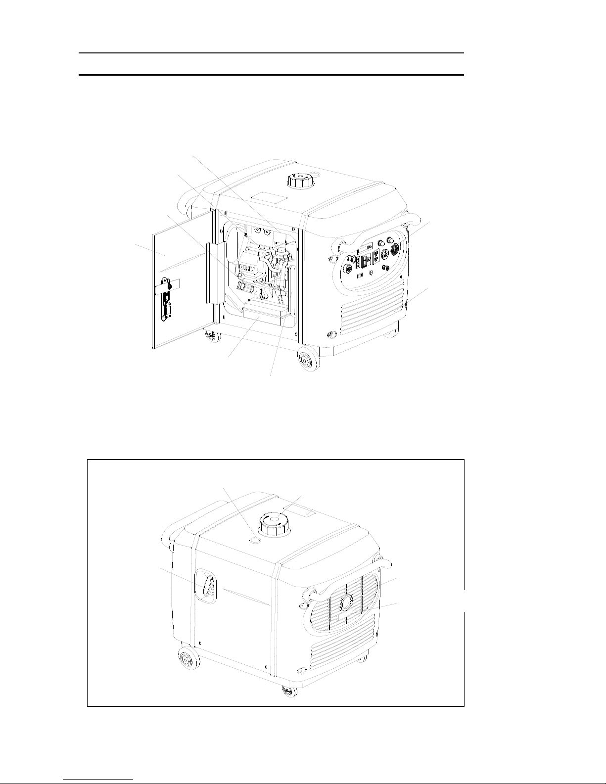
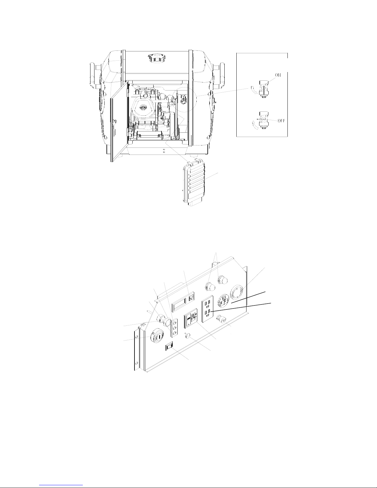
2. COMPONENT LOCATIONS ······························································································· 3
2.1 Outside View ··············································································································· 3
2.2 Control Panel ··············································································································4
2.3 Serial Number and Bar Code Location······································································· 5
3. PRE-OPERATION CHECK ································································································· 6
3.1 Engine Oil···················································································································· 6
3.1 Fuel ····························································································································· 7
3.3 Air Cleaner ··················································································································7
4. STARTING THE ENGINE ···································································································9
4.1 Starting Procedure ······································································································9
4.2 High Altitude Operation····························································································· 12
4.3 Ambient Temperature ·······························································································12
5. GENERATOR USE ··········································································································· 13
5.1 Warnings and Cautions·····························································································13
5.2 AC Power Applications ·····························································································14
5.3 VoltageSelectionSwitch··························································································15
5.4 ACPowerOperation·································································································15
5.5 OutputandOverloadIndicators················································································16
5.6 SmartThrottle··········································································································· 17
5.7 AirConditionerOperation·························································································18
5.8 DCPowerOperation·································································································18
5.9 LowOilAlarmSystem······························································································· 20
5.10DigitalDisplayPanel·································································································· 20
6. STOPPING THE ENGINE·································································································22
6.1 Normal Shutdown ····································································································· 22
6.2 Emergency Stop ·······································································································22
7. MAINTENANCE ················································································································ 23
7.1 Emission Control System ······················································································23
7.2 Maintenance Schedule ····························································································· 25
7.3 Changing Oil ············································································································· 25
7.4 Air Cleaner Service ··································································································· 26
7.5 Spark Plug Service ···································································································27
7.6 Spark Arrestor Maintenance ·····················································································28

8. TRANSPORTING/STORAGE ···························································································29
8.1 Transporting ··············································································································29
8.2 Extended Storage ····································································································· 29
8.3 Fuel Treatment and Generator Exercise ··································································29
9. TROUBLESHOOTING ······································································································ 30
10. SPECIFICATIONS ·········································································································· 32
11. WIRING DIAGRAM ·········································································································33
12. WHEEL KIT INSTALLATION ·························································································· 34
13. WARRANTY ····················································································································36
13.1LimitedWarranty-Kipor Power Products ································································ 36
13.2EmissionControlWarranty······················································································37
13.3CaliforniaEmissionsControlWarrantyStatement·················································· 39
14. EMISSION CONTROL SYSTEM ····················································································40

1
1. SAFETY INSTRUCTIONS
■Our generators are designed to give safe and dependable service if
operated according to these instructions.
Read and understand the owner's manual before operating the
generator. Failure to do so could result in personal injury or
equipment damage.
■Exhaust gas contains poisonous carbon monoxide.
Never run the generator in an enclosed area.
Be sure to provide adequate ventilation.
The muffler becomes very hot during operation and remains hot for
several minutes after stopping the engine.
Be careful not to touch the muffler while it is hot.
Let the engine cool before storing the generator indoors.
The engine exhaust system will be heated during operation and
remain hot immediately after stopping the engine.
To prevent burns, pay attention to the warning marks attached to the
generator.
Thegeneratormustbeoperatedoutsidewithadequateventilation.It
cannotbe operated in an enclosed compartment of any vehicle or
garagearea.

2
To ensure safe operation:
■Gasoline is extremely flammable and explosive under certain
conditions. Refuel in a well ventilated area with the engine stopped.
■Keep away from smoking materials, sparks and other sources of
combustion when refueling the generator. Always refuel in a
well-ventilated location.
■Wipe up spilled gasoline at once.
■Restrict use of the generator in high-hazard risk areas.
■Connections for standby power to a building's electrical system must
be made by a qualified electrician and must comply with all applicable
laws and electrical codes. Improper connections can allow electrical
current from the generator to back feed into the utility lines. Such
back feed may electrocute utility company workers or others who
contact the lines during a power outage, and when utility power is
restored, the generator may explode, burn, or cause fires in the
building's electrical system. This generator is not designed to be
connected to an automatic transfer switch. Serious damage to the
engine and inverter module may result.
■Always make a pre-operation inspection before you start the engine.
■Place the generator at least three feet or one meter away from
buildings or other equipment during operation.
■Operate the generator on a level surface to prevent fuel spillage or oil
starvation.
■Know how to stop the generator quickly and understand operation of
all the controls. Never permit anyone to operate the generator
without proper instructions. Keep children and pets away from the
generator when it is in operation.
■Never operate the generator with the door open or any panels
removed. Do not operate in any enclosure such as an RV
compartment.
■Keep away from rotating parts while the generator is running.
■The generator is a potential source of electrical shocks when
misused; do not operate with wet hands.
■Do not operate the generator in rain or snow or let it get wet.

3
2. COMPONENT LOCATIONS
2.1 Outside view
起动手柄
油位指示器 加油盖
排气口
高温标记
空气指数信息铭牌
Fuel Level Indicator
Fuel Filler Cap
Air Quality Index
Air Exhaust
Muffler Warning
Starter Grip
火花塞
机油尺
维修门
电瓶
空滤
进气口
控制面板
碳罐
Carbon Canister
Control Panel
Inlet
Air Filter
Battery
ServiceDoor
Oil Dipstick
Spark Plug

4
2.2 Control panel
交流插座
接地端
发动机开关
阻风门手柄
液晶显示器
直流插座
机油位报警(红)
过载指示(红)
工作指示(绿)
智能开关
电压选择开关
过载保护器
油开关
空滤盖
IG4300 Fuel Switch
240V AC Receptacle
Circuit Protector
LED Monitor
Ground Terminal
Smart Throttle
Electric Starter
Choke
Low Oil Alarm (RED)
Voltage Selection Switch
DC Receptacle
Overload Alarm (RED)
Output Indicator (GREEN)
30A 120V Receptacle
GFCI Receptacle
Air Filter Cover
Air Filter Cover
Filter

5
2.3 Serial Number Location
The engine serial number is stamped on the engine block to the left of the oil drain plug. In most cases
the battery will have to be removed to view it clearly. Refer to this number when ordering parts or
making technical inquiries.
Engine serial number
Please record this information below and keep this manual in a safe place along with the bill of sale.
Serial Number __________________________________
Date of Purchase ________________________________
Place of Purchase ________________________________
Engine serial number

6
3. PRE-OPERATION CHECK
Be sure to check the generator on a level surface with the engine stopped. Under no circumstances
can this generator be installed in an enclosed compartment.
3.1 Engine Oil Level
■Using non-detergent oil or 2-stroke engine oil could shorten the
engine's service life.
■Use a high-detergent, premium quality 4-stroke engine oil, certified to
meet or exceed U.S. automobile manufacturer's requirements for API
Service Classification SG/SF.
■Select the appropriate viscosity for the average temperature in your
area.
SAE Viscosity Grades
Open the left maintenance cover. Remove and wipe the oil dipstick with a clean rag. Check the oil level by
inserting the dipstick in the filler hole, tighten the dipstick and screw it out. If the oil level is below the end of
the dipstick, refill with recommended oil to the top of the oil filler neck.
Single
viscosity
Multi-
viscosity
Ambient Temperature
上限位
下限位
机油尺
Dipstick
Upper limit
Lower limit

7
■Running the engine with insufficient oil can cause serious engine
damage.
■The Low Oil Alarm System will automatically stop the engine before
the oil level falls below asafe limit. However, to avoid the
inconvenience of an unexpected shutdown, it is still advisable to
visually inspect the oil level regularly.
3.2 Fuel
Fuel tank capacity-3.1 gal (11.6 L)
Use unleaded 87 octane regular grade automotive gasoline.
If the fuel level is low, refill to the shoulder of the fuel strainer, see fig.4.
Never use an oil/gasoline mixture or dirty gasoline.
Avoid getting dirt, dust or water in the fuel tank.
After refueling, tighten the fuel filler cap securely.
■Gasoline is extremely flammable and is explosive under certain
conditions.
■Refuel in a well-ventilated area with the engine stopped. Keep all
smoking materials, sparks, and any other source of combustion away
from the generator during refueling.
■Do not overfill the fuel tank (there should be no fuel in the filler
neck). After refueling, make sure the fuel filler cap is closed
properly and securely.
■Be careful not to spill fuel when refueling. Spilled fuel or fuel vapor
may ignite. If any fuel is spilled, make sure the area is dry before
starting the engine.
■Avoid repeated or prolonged contact with skin or breathing of vapor.
KEEP OUT OF REACH OF CHILDREN.
Fuel surface
Fuel surface
Strainer
Fuel filler cap

8
Gasoline containing alternate fuels:
If you decide to use a gasoline containing ethanol, be sure its octane rating is no lower than the
specification. Do not use a blend that contains more than 10% ethanol. Do not use any gasoline
containing methanol.
3.3 Air Cleaner
Check the air cleaner element to be sure it is clean and in good condition.
Open the left side maintenance cover. Remove the air cleaner cover, remove the paper element from
the air cleaner cover, and check the element, Replace the element if dirty or the filter paper is torn.
■Never run the engine without the air cleaner. Rapid engine wear will
result from contaminants such as dust and dirt being drawn through
the carburetor into the engine.
空滤底座
滤芯 空滤盖
Air cleaner base
Air filter element
Air cleaner cover

9
4. STARTING THE ENGINE
■When starting the generator after adding fuel for the first time or after
long term storage, or after running out of fuel, turn the fuel valve lever
to the "ON" position, then wait for 10 to 20 seconds before starting
the engine.
4.1 Starting Procedure
4.1(a) Turn the fuel valve lever to the ON position.
油开关
空滤盖
IG4300 Fuel Switch

10
4.1(b) Pull the choke knob out to the CLOSED position
Do not use the choke if the engine is already warm or the ambient air temperature is high.
4.1(c) Insert the engine key and turn the engine switch to ON position.
Engine switch
阻风门开关
Choke knob

11
4.1(d) Electric Start: turn the engine switch to the START until the engine has started.Do not operate
the starter for more than 10 seconds.
Manual Start: pull the starter grip lightly until resistance is felt then pull the starter grip briskly
toward the arrow as shown below.
■Do not allow the starter grip to snap back. Return it slowly by hand.
■Do not let the starter rope rub against the generator body or the rope
will wear out prematurely.
4.1(e) Push the choke knob in to the OPEN position as the engine warms up.
Fig.9(a)
Fig.9(b)
Engine switch
Starter grip
阻风门开关
Choke Knob

12
4.2 High altitude operation
At high altitude, the standard carburetor air-fuel mixture will be excessively rich
Performance will decrease, and fuel consumption will increase.
High altitude performance can be improved by installing a smaller diameter main fuel jet in the
carburetor. If you always operate the generator at altitudes higher than 5000 feet or 1500 meters
above sea level, have your authorized dealer install a high altitude main jet.
Even with suitable carburetor jetting, engine horsepower will decrease approximately 3.5% for each
1000 feet or 305 meter increase in altitude. The effect of altitude on the horsepower will be greater
than this if no carburetor modification is made.
■Operation of the generator at an altitude lower than the carburetor is
jetted for may result in reduced performance, overheating, and
serious engine damage caused by an excessively lean air/fuel
mixture. Be sure to have any modification reversed at lower altitudes.
4.3Ambient Temperature
Generator output generally derates 1% for every 10° F (5.5° C) above 85° F (29° C). The normal
operating range of the generator is -20° to 113° F (-29° to 45° C).
■Do not operate the generator when the ambient temperature is below
-20° F (-29°)
■Do not operate the generator when the ambient temperature is above
113°F(45° C)

13
5. GENERATOR USE
5.1 Warnings and Cautions
■To prevent electrical shock from faulty appliances, the generator
should be grounded. Connect a length of heavy cable between the
generator's ground terminal and an external ground source.
■Connections for standby power to a building's electrical system must be made by a qualified
electrician and must comply with all applicable laws and electrical codes. Improper connections can
allow electrical current from the generator to back feed into the utility lines. Such back feed may
electrocute utility company workers or others who contact the lines during a power outage;when utility
power is restored, the generator may explode, burn, or cause fires in the building's electrical system.
Do not connect this generator to an automatic transfer switch. Serious damage to the engine and
inverter module may result.
■Limit operation requiring maximum power to 30 minutes.
For continuous operation do not exceed the rated power of 2800 watts or 23.3 amps.
■Do not exceed the current limit specified for any one receptacle.
■Do not modify or use the generator for other purpose other than what it was intended. Also observe
the following when using the generator:
•Do not attempt to connect generators in parallel.
•Do not connect an extension to the exhaust pipe.
•Do not operate with any covers removed or in a closed compartment

14
■Whenanextensioncableisrequired,makesureyouusethepropersizeandlength.
•16 Gauge Cords-Any 16 gauge cord between 0 and 100 feet long will adequately handle tool and appliance
loads up to 10 amps
•14 Gauge Cords-a 14 gauge cord between 0 and 50 feet long will adequately handle loads between 10 and
15 amps.
•12 Gauge Cords-If your load is between 10 and 15 amps and the length of the cord is 50 to 100 feet, you need
a 12 gauge cord to safely power any tool.
■Keep the generator away from other electric cables or wires such as commercial power supply
lines.
■You may use DC receptacle when using AC supply.
5.2 AC Power Application
The generator has the capability to provide 120V and 240V AC Power. It can do so simultaneously
depending on the needs of the user. However, it is important to understand the receptacles, their
current limitations. andhowto distribute power efficiently.
120V20AGFCIReceptacle 20/240V30AReceptacle
Voltage Selection Switch 20V30AReceptacle
The GFCI (ground fault circuit interrupter) shuts off power to the protected receptacles if a ground fault
or current imbalance between two conductors is detected. If the reset button pops out, the appliance
connected to the receptacle may be defective. If the appliance appears to be in good condition, press
the reset button until a click is heard. This will restore power. If the reset button pops out again,
Table of contents
Other Kipor Inverter manuals

Kipor
Kipor IG1000 User manual

Kipor
Kipor IG3000 User manual

Kipor
Kipor KG390 User manual

Kipor
Kipor Sinemaster IG2600 User manual

Kipor
Kipor IG3000E User manual

Kipor
Kipor IG6000 User manual

Kipor
Kipor KGE2500X User manual

Kipor
Kipor Sinemaster IG2000i User manual

Kipor
Kipor K DE2200X/E User manual

Kipor
Kipor IG3000 User manual

Kipor
Kipor IG3000E User manual

Kipor
Kipor GS1000 User manual

Kipor
Kipor KGE4000X User manual

Kipor
Kipor KDE11SS Installation manual

Kipor
Kipor K DE2200X Installation manual

Kipor
Kipor IG6000 User manual

Kipor
Kipor IG6000 User manual

Kipor
Kipor KGE12E User manual

Kipor
Kipor KGE3000Ti Install guide

Kipor
Kipor KDE12EA User manual