Kleinn RZR1000-KIT User manual


RZR1000-KIT
Install Guide
Go to Table of Contents PG 2/35 REV: B (1/11/2023)
Table of Contents
Table of Contents .......................................................................................................................................................2
List of Figures..............................................................................................................................................................4
1. How to Use this Manual .....................................................................................................................................5
1.1. Illustration/Photo Details and Orientation ................................................................................................5
2. Safety First ..........................................................................................................................................................5
3. Application Chart................................................................................................................................................6
3.1. 100% Direct Bolt-On Vehicle List................................................................................................................6
3.2. Excluded Vehicles.......................................................................................................................................6
3.3. Aftermarket Product Compatibility............................................................................................................6
4. Kit Installation Overview ....................................................................................................................................7
4.1. Approximate Installation Time...................................................................................................................8
4.2. Quick Install Outline ...................................................................................................................................8
5. List of Tools and Supplies ...................................................................................................................................9
5.1. Standard Tool List (Required).....................................................................................................................9
5.2. Special Tool List (Recommended) ..............................................................................................................9
5.3. Shop Consumables List (Recommended)...................................................................................................9
6. Parts List .......................................................................................................................................................... 10
6.1. Primary Kit Components ......................................................................................................................... 10
6.2. Air Fittings and Related Items ................................................................................................................. 11
6.3. Electrical Components and Related Items .............................................................................................. 12
6.4. Bolt-On Mounting Brackets & Special Hardware.................................................................................... 13
7. Bench Assembly............................................................................................................................................... 14
7.1. Assemble Fittings to Tank ....................................................................................................................... 14
7.2. Compressor Disassembly – Bushings & Bolts.......................................................................................... 14
7.3. Trumpet Support Clamp.......................................................................................................................... 17
7.4. Trumpet Support Assembly .................................................................................................................... 18
8. On-Vehicle Installation .................................................................................................................................... 19
8.1. Vehicle Preparation................................................................................................................................. 19
8.2. Air Tank Brackets Installation.................................................................................................................. 21
8.3. Air Compressor Bracket Installation ....................................................................................................... 23

RZR1000-KIT
Install Guide
Go to Table of Contents PG 3/35 REV: B (1/11/2023)
8.4. Turbo Only: Re-install Firewall Heat Shield............................................................................................. 24
8.5. Air Tank Installation, Preliminary............................................................................................................ 24
8.6. Air Compressor Installation..................................................................................................................... 25
8.7. Air Tank Installation, Final....................................................................................................................... 26
8.8. Connect Air Compressor to Air Tank....................................................................................................... 27
8.9. Connect Air Compressor to Inlet Filter ................................................................................................... 28
8.10. Attach Air Horn Brackets and Air Horn ................................................................................................... 28
8.11. Connect Air Tubing.................................................................................................................................. 30
8.12. Re-Connect Air Intake and Drive-Belt Cooling Tube ............................................................................... 30
9. On-Vehicle Electrical Installation..................................................................................................................... 31
10. Initial Testing of Kit.......................................................................................................................................... 33
10.1. If Disconnected, Reconnect Vehicle Battery(s)....................................................................................... 33
10.2. Test Air Compressor................................................................................................................................ 33
10.3. Test Train Horns ...................................................................................................................................... 33
10.4. Test Quick Connect Coupler.................................................................................................................... 33
11. General Operation of Kit ................................................................................................................................. 34
11.1. Compressor Operation............................................................................................................................ 34
11.2. Horn Operation ....................................................................................................................................... 34
12. Routine Maintenance ...................................................................................................................................... 34
13. Warranty Information ..................................................................................................................................... 35

RZR1000-KIT
Install Guide
Go to Table of Contents PG 4/35 REV: B (1/11/2023)
List of Figures
Figure 1 - Back Driver View Showing Air Horn Location.............................................................................................7
Figure 2 - Back Passenger View Showing Air System Location...................................................................................7
Figure 3- Air Tank Fitting Locations ......................................................................................................................... 14
Figure 4- Compressor Disassembly.......................................................................................................................... 14
Figure 5- Compressor Hardware Installation .......................................................................................................... 15
Figure 6- Rubber Bushing & Brass Sleeve Installation............................................................................................. 15
Figure 7- Bracket Shown with Bushings & Sleeves Installed ................................................................................... 16
Figure 8- Rubber Grommet Cut Template............................................................................................................... 17
Figure 9- Trumpet Support Assembly...................................................................................................................... 18
Figure 10 - Drive Belt Cooling Tubing, to Remove................................................................................................... 19
Figure 11 - Air Intake Tubing, Removal ................................................................................................................... 20
Figure 12 - Firewall Heat Shield, Removal............................................................................................................... 20
Figure 13- RZR-201 (right) & RZR-202 (left) Hardware Preparation........................................................................ 21
Figure 14 - Driver Side Sway Bar Nuts/Bolts, to Remove ........................................................................................ 21
Figure 15- Tank Brackets Installed........................................................................................................................... 22
Figure 16- Compressor Bracket Installation, Part 1................................................................................................. 23
Figure 17- Compressor Bracket Installation, Part 2................................................................................................. 23
Figure 18- Tank Installation ..................................................................................................................................... 24
Figure 19 - Air Tank to Vehicle Clearance................................................................................................................ 25
Figure 20- Air Compressor Installed onto Compressor Bracket .............................................................................. 26
Figure 21- Tank Hardware Access from Oil Filter Panel .......................................................................................... 26
Figure 22 - Driver Side Sway Bar Final Torque of Nuts/Bolts .................................................................................. 27
Figure 23 - Air Compressor Final Install with Leader Hose Connection to Air Tank................................................ 27
Figure 24- Horn Bracket Installation 1..................................................................................................................... 28
Figure 25- Horn Bracket Installation 2..................................................................................................................... 29
Figure 26- Air Horn Installation ............................................................................................................................... 29
Figure 27 - Air Horn Installed to Brackets and Frame ............................................................................................. 30
Figure 28 – Suggested Wiring Diagram for Air System............................................................................................ 31
Figure 29- Illuminated Rocker Switch Wiring Diagram............................................................................................ 32

RZR1000-KIT
Install Guide
Go to Table of Contents PG 5/35 REV: B (1/11/2023)
1. How to Use this Manual
1.1. Illustration/Photo Details and Orientation
This manual may use digitally created illustrations, and/or actual photos of example vehicle. These graphics may
not include exact items found on your vehicle (i.e., electrical wiring, fuel lines, body panels, etc.). Illustrations
typically will be missing details and are for clarity to show critical mounting locations and orientation on vehicle.
Throughout this manual, yellow arrows with text reading “FRONT”, may be
present over illustrations and pictures. These arrows specify direction toward
front of vehicle and provide clarity to how illustration is viewed.
2. Safety First
Read manual thoroughly before starting installation of this kit. Verify you have all parts listed and that you
clearly understand this installation procedure. Contact Kleinn technical support for any questions.
Installation of this kit requires moderate mechanical aptitude; seek professional help if you’re not competent
using hand tools in tight uncomfortable spaces, and around possibly rusted and sharp vehicle parts.
Before starting, obtain proper tools required to perform installation correctly, adequate lighting, eye protection,
hearing protection for operating train horns, and hand protection to guard against sharp edges and metal burrs,
which may be present on kit parts and vehicle parts.
Throughout this manual the following words may be used; be aware of their meaning and application.
CAUTION: means damage could occur to vehicle, or kit parts during, or after installation
WARNING: means injury could occur to you or others, including damage to vehicle, or kit parts
DANGER: means serious injury or death could occur to you or others during installation
FRONT

RZR1000-KIT
Install Guide
Go to Table of Contents PG 6/35 REV: B (1/11/2023)
3. Application Chart
3.1. 100% Direct Bolt-On Vehicle List
RZR1000-KIT is a 100% direct bolt-on aftermarket product for POLARIS vehicles listed in below chart; every effort
has been made to verify correct fitment on these vehicles in their factory, non-modified conditions.
MODEL YR
MODEL
DRIVE
ENGINE
BODY
TRIM
2014-2019
RZR 1000 XP
ALL
NON-TURBO
ALL
ALL
2014-2019
RZR 1000 XP
ALL
TURBO
ALL
ALL
NOTE: All vehicles listed may require drilling holes for ground wires and installing switches,
based on preference of installed switch locations and wire grounding points.
3.2. Excluded Vehicles
This kit MAY NOT be compatible with following:
All trim packages with upgraded rear body panels (i.e., rock protection, aggressive flairs, etc.)
All trim packages with self-adjusting/automatic suspension, such as Polaris DYNAMIX
All trim packages with high-flow air intakes/clutch cooling, or snorkel style tubing
Vehicles with these OEM upgrades may require body, chassis, or kit modifications to properly install
Review this manual in full before unpackaging kit and verify correct space and mounting locations exist with
your trim package
3.3. Aftermarket Product Compatibility
This kit has NOT been designed, or tested for use with aftermarket rear suspension trailing arms, sway bars,
sway bar disconnects, exhaust systems, bolt-on turbo/super chargers, air intake systems, etc.
RZR1000-KIT
Install Guide
Go to Table of Contents PG 7/35 REV: B (1/11/2023)
4. Kit Installation Overview
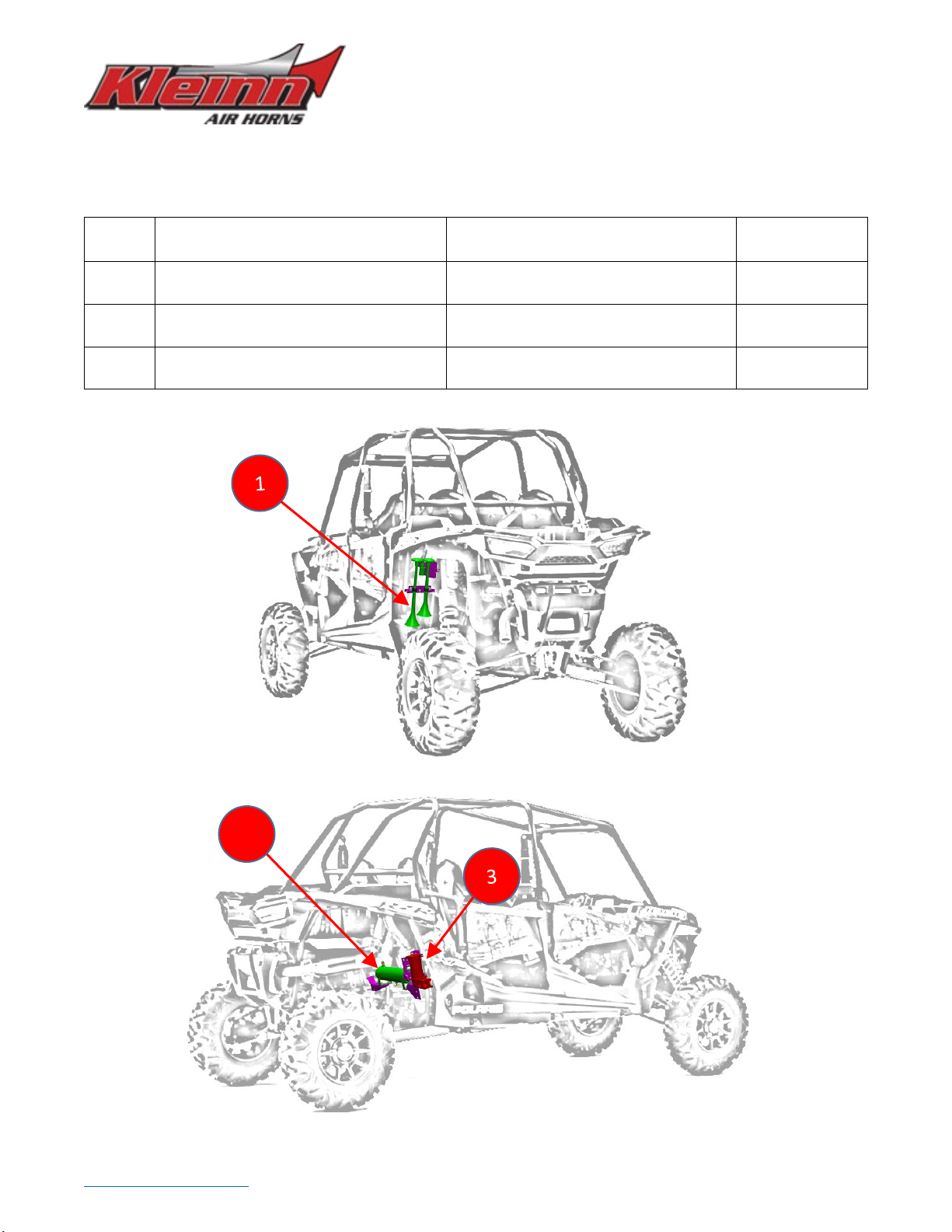
RZR1000-KIT consists of following sub-systems, located on vehicle, as follows:
ITEM DESCRIPTION MOUNTING LOCATION
INSTALL TIME
(approx.)
1
102 Series Dual Horn with Air Solenoid
Directly behind rear firewall, on Driver
side, mounted to frame tubing
1+ Hours
2
1 Gal. Air Tank
Directly behind rear firewall, mounted
between chassis sway bar mounts
2+ Hours
3
6350RC Air Compressor
Directly behind rear firewall, on Pass.
side, mounted to frame tubing
1-2 Hours
Figure 1 - Back Driver View Showing Air Horn Location
Figure 2 - Back Passenger View Showing Air System Location
2

RZR1000-KIT
Install Guide
Go to Table of Contents PG 8/35 REV: B (1/11/2023)
4.1. Approximate Installation Time
RZR1000-KIT is a multi-faceted product consisting of multiple mechanical, electrical, and pneumatic
components.
For a typical home mechanic, auto enthusiast, or technician installing a Kleinn Bolt-On kit for first time, a
professional installation job with setup and testing of final product, is estimated to take:
5-8 Hours
4.2. Quick Install Outline
For person(s) with experience installing Kleinn bolt-on kits, RZR1000-KIT can be installed in an order similar to
below:
1. Install Tank Fittings
2. Disassemble & Prep Compressor & Compressor Bracket
3. Assemble Trumpet Support Brackets
4. Remove Cooling Tube, Intake Tube & Firewall Heat Shield (Turbo Only)
5. Disconnect Sway Bar, Prep & Install Air Tank Brackets
6. Install Compressor Bracket
7. Reinstall Heat Shield (Turbo Only)
8. Install Air Tank
9. Install Air Compressor
10. Plumb Air Compressor to Air Tank
11. Install Air Horn Brackets & Air Horns
12. Plumb Air Horn to Tank
13. Install & Plumb 1302 Quick Connect Kit to Tank
14. Reconnect Cooling & Intake Tube
15. Electrical Hookup of Air System
16. Electrical Hookup of Air Horn Switch
17. Test System

RZR1000-KIT
Install Guide
Go to Table of Contents PG 9/35 REV: B (1/11/2023)
5. List of Tools and Supplies
5.1. Standard Tool List (Required)
•Basic mechanic’s 3/8” drive socket sets with extensions
•Basic mechanic’s 3/8” socket swivel/UV-Joint
•Basic mechanic’s combination wrenches
•Inch Size Wrenches (1/4” – 1” Hex)
•Metric Size Wrenches (6mm – 20mm Hex)
•Basic mechanic’s hex wrench/hex driver set
•Metric Size Hexes (4mm-8mm)
•Basic mechanic’s screwdriver set (Philips, Flat Head)
•Diagonal Cutter/Wire Cutter Pliers
•Wire Strippers
•Wire Terminal Crimpers
•Slip-Joint Pliers
•Utility Knife
•Magnetic retrieval tool
5.2. Special Tool List (Recommended)
•10-100 ft.-lb. torque wrench
•20-150 in.-lb. torque wrench
•Multi-Meter for 12V DC electrical systems, or equivalent
•12V DC Test Light, or equivalent
•Trim Panel Tool
5.3. Shop Consumables List (Recommended)
•Quality Electrical tape
•Di-electric grease for electrical connections
•Silicone grease, or equivalent for rubber compressor bushings
•Heat Shrink tubing for electrical connections
•Medium-Strength Loctite (i.e., Blue) (i.e., Loctite PN 242), or equivalent
•Sandpaper, or Wire Brushes for installing ground wires
•Extra plastic zip ties > 6” long
•Extra NPT sealant (i.e., Kleinn Air Horn Juice, Teflon tape, etc.)
•Touch-up paint for frame/chassis
•Typical cleanup supplies

RZR1000-KIT
Install Guide
Go to Table of Contents PG 10/35 REV: B (1/11/2023)
6. Parts List
Unpackage and organize Kit across a large work area and verify all parts are included, as listed below. Contact
Kleinn support if any questions arise.
6.1. Primary Kit Components
Items in this section come in their own packages and may include additional items inside package.
ITEM
QTY
PART NUMBER
DESCRIPTION
PICTURE
-
1
6350RC
6350RC Compressor Kit,
with included hardware,
and remote air supply
line
-
1
102-1
102 Series Horn Kit, with
included solenoid/valve
-
1
6230RT
Air Tank, 1 Gal., 6 Ports
-
1
1302
Remote Quick Connect
Coupler Relocation Kit
(May be inside INF-1)
-
1
INF-1
Tire Inflation Kit
RZR1000-KIT
Install Guide
Go to Table of Contents PG 11/35 REV: B (1/11/2023)
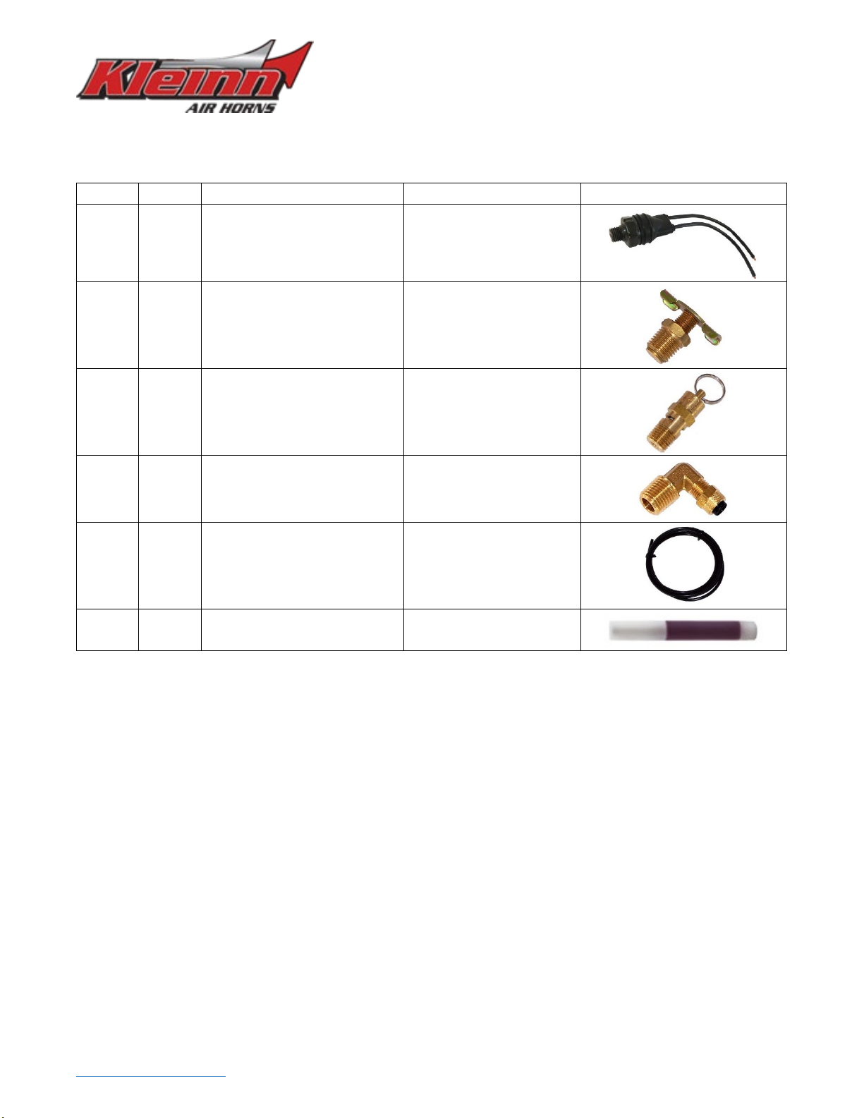
6.2. Air Fittings and Related Items
ITEM
QTY
PART NUMBER
DESCRIPTION
PICTURE
F1
1
2151
¼” NPT Pressure Switch
F2
1
52835
¼” NPT, Drain Valve
F3
1
52175
¼” NPT, 175 PSI
Safety Valve
F4
1
51414L
¼” NPT Elbow
Compression Fitting
F5
12 ft
25014
1/4” Air Tubing,
F6
2
JUICE
Thread Sealant for NPT
Fittings
RZR1000-KIT
Install Guide
Go to Table of Contents PG 12/35 REV: B (1/11/2023)
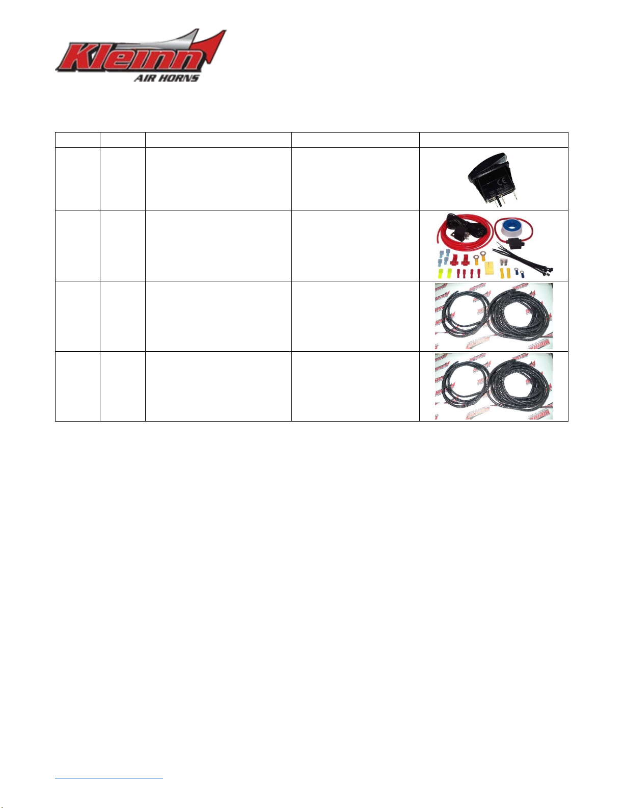
6.3. Electrical Components and Related Items
ITEM
QTY
PART NUMBER
DESCRIPTION
PICTURE
E1
1
321W
Lighted Rocker Switch,
White
E2
1
WIRE KIT
Full Wire Kit, with
electrical connectors and
zip ties
E3
15 ft
¼” WIRE LOOM
1/4” Wire loom for
electrical routing
E4
15 ft
1/8” WIRE LOOM
1/8” wire loom for
electrical routing

RZR1000-KIT
Install Guide
Go to Table of Contents PG 13/35 REV: B (1/11/2023)
6.4. Bolt-On Mounting Brackets & Special Hardware
ITEM
QTY
PART NUMBER
DESCRIPTION
PICTURE
K1
1
RZR-101
COMPRESSOR BRACKET,
INNER HALF
K2
3
RZR-102
SPACER, BRACKET HALF
K3
1
RZR-103
COMPRESSOR BRACKET,
OUTER HALF
K4
1
RZR-201
TANK BRACKET,
PASSENGER SIDE
K5
1
RZR-202
TANK BRACKET, DRIVER
SIDE
K6
1
RZR-301
HORN BRACKET, FRONT
HALF
K7
1
RZR-302
HORN BRACKET, BACK
HALF
K8
1
RZR-303
TRUMPET SUPPORT
CLAMP, BOTTOM HALF
K9
1
RZR-304
TRUMPET SUPPORT
CLAMP, TOP HALF
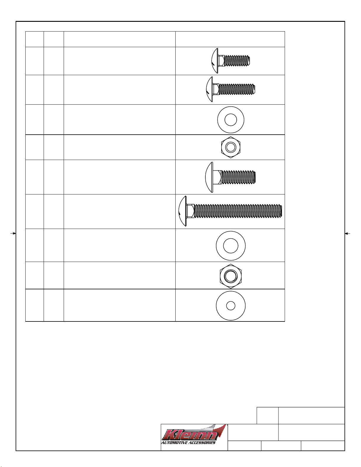
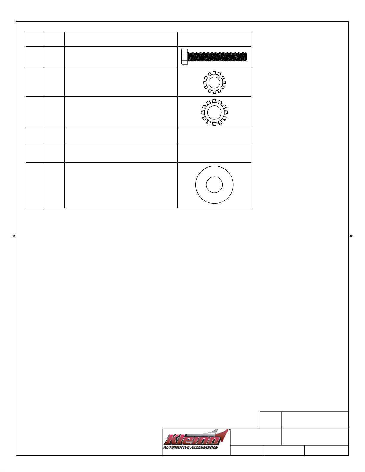
NOTE:
SCALE IMAGES OF PREPACKAGED HARDWARE INCLUDED WITH HORNS, COMPRESSOR, TANK ARE
NOT ILLUSTRATED ON THIS SHEET
SCALE IMAGES OF UNIQUE & IDENTIFIABLE HARDWARE ARE NOT INCLUDED ON THIS SHEET
PRINT AT 100% SCALE
ITEM
#
QTY
DESCRIPTION
SCALE IMAGE
H1
9
1/4"-20 CARRIAGE BOLT,
0.75" LENGTH
H2
4
1/4"-20 CARRIAGE BOLT,
1.00" LENGTH
H3
13
1/4" WASHER
H4
13
1/4"-20 HEX NUT
H5
4
5/16"-18 CARRIAGE BOLT,
1.00" LENGTH
H6
3
5/16"-18 CARRIAGE BOLT,
2.25" LENGTH
H7
3
5/16" WASHER, SAE
H8
7
5/16"-18 HEX NUT
H9
8
#10 FLAT WASHER
1/5/2023
SCALE_H
RZR1000-KIT
A
NOTE:
SCALE IMAGES OF PREPACKAGED HARDWARE INCLUDED WITH HORNS, COMPRESSOR, TANK
ARE NOT ILLUSTRATED ON THIS SHEET
SCALE IMAGES OF UNIQUE & IDENTIFIABLE HARDWARE ARE NOT INCLUDED ON THIS SHEET
PRINT AT 100% SCALE
ITEM
#
QTY
DESCRIPTION
SCALE IMAGE
H10
2
M5 x 0.8 HEX SCREW
35MM LENGTH
H11
13
1/4" EXTERNAL TOOTH WASHER
H12
7
5/16" EXTERNAL TOOTH WASHER
H13
2
RUBBER GROMMET
NOT ILLUSTRATED
H14
2
HOSE CLAMP
NOT ILLUSTRATED
H15
4 5/16" WASHER, USS
1/5/2023
SCALE_H
RZR1000-KIT
A

RZR1000-KIT
Install Guide
Go to Table of Contents PG 14/35 REV: B (1/11/2023)
7. Bench Assembly
Complete the following steps off-vehicle to facilitate installation.
7.1. Assemble Fittings to Tank
•Apply two small drops of F6 JUICE to each male pipe thread.
•Attach air fittings to tank, per the below illustration.
•Hand-tighten each fitting, then further tighten each 1/4 - 1/2 turn; adjust as necessary to match
fitting orientation.
Figure 3- Air Tank Fitting Locations
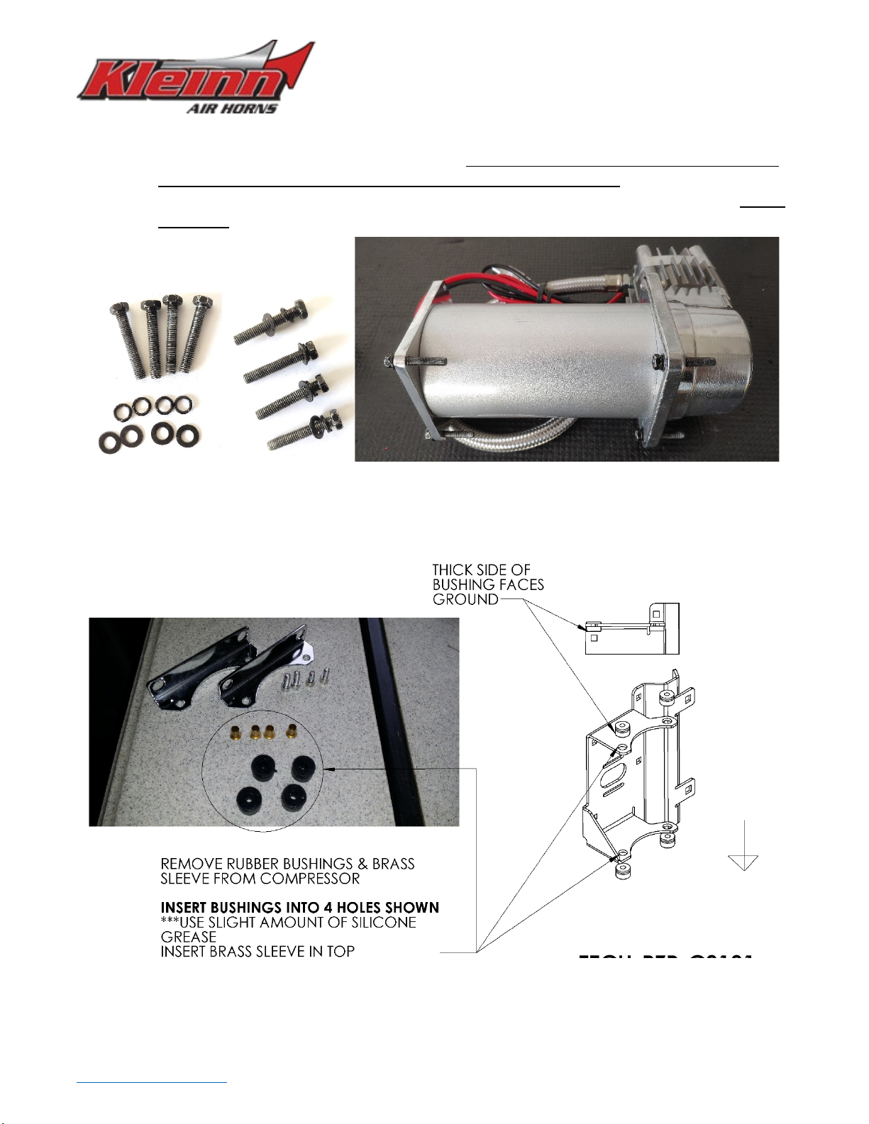
7.2. Compressor Disassembly – Bushings & Bolts
•Remove the compressor from its packaging, then remove Brass sleeves and Rubber bushings; set
aside for re-use.
•Remove the feet from Compressor and discard. See below.
Figure 4- Compressor Disassembly
SAVE
REMOVE
RZR1000-KIT
Install Guide
Go to Table of Contents PG 15/35 REV: B (1/11/2023)
•Open the hardware bag that is included with the compressor & install two (2) of the bolts, lock
washers, and flat washers onto the compressor; use hardware H10 along with the remaining two
lock washers & flat washers on the side closest to the compressor head (right side, figure 5). It is
recommended to apply Medium-Strength thread locker to threads before installation, then Torque
to 20 in-lbs
Figure 5- Compressor Hardware Installation
•Install the previously removed rubber bushings & brass sleeves onto the compressor bracket as
shown below.
Figure 6- Rubber Bushing & Brass Sleeve Installation


Table of contents
Other Kleinn Automobile Accessories manuals


Popular Automobile Accessories manuals by other brands

Dakota Digital
Dakota Digital CMD-1000 manual

Versahaul
Versahaul MAGNUM TIE-DOWN STRAP instructions

travall
travall TDG 1600 Fitting instructions

Whelen Engineering Company
Whelen Engineering Company MirrorBeam MBCV96 installation guide

OYPLA PETS
OYPLA PETS 3775 user manual

Prorack
Prorack K906 Fitting instructions


