Kleinn GMHD20-OBA User manual


Install Guide GMHD20-OBA
Page | 2 Revision: A
Table of Contents
1. Application Chart .................................................................................................................................. 4
1.1. List of compatible vehicles............................................................................................................ 4
1.2. Incompatible Vehicle Features & Packages .................................................................................. 4
1.3. Aftermarket Product Compatibility .............................................................................................. 4
2. Before You Start.................................................................................................................................... 5
3. Installation Overview ............................................................................................................................ 5
3.1. Kit Layout & Location.................................................................................................................... 5
4. List of Tools & Supplies ......................................................................................................................... 6
4.1. Standard Tools .............................................................................................................................. 6
4.2. Specialty Tools .............................................................................................................................. 6
4.3. Consumables................................................................................................................................. 6
5. Parts List................................................................................................................................................ 7
5.1. Primary Kit Components ............................................................................................................... 7
5.2. Fittings & Related Items................................................................................................................ 8
5.3. Electrical Components & Related Items ....................................................................................... 9
5.4. Mounting Brackets........................................................................................................................ 9
5.5. Hardware & Related Items.......................................................................................................... 10
6. Recommended Routing of Air Tubing & Wire ....................................................................................11
7. Bench Assembly .................................................................................................................................. 12
7.1. Rubber Trim – Cutting & Installation ..........................................................................................12
7.2. Air Tank – Fitting Installation ......................................................................................................13
7.3. Compressor – Fitting Installation................................................................................................ 13
7.4. INF-1 – Fitting Installation........................................................................................................... 13
8. On-Vehicle Assembly ..........................................................................................................................14
8.1. Compressor Installation..............................................................................................................14
8.2. Tank Installation.......................................................................................................................... 18
8.3. Air Tank Installation ....................................................................................................................21
8.4. 1302 Remote Air Quick Connect.................................................................................................22
8.5. Final System Plumbing ................................................................................................................22
9. On-Vehicle Electrical Installation ........................................................................................................23
9.1. Solenoid Connector – Reconfigure the Housing & Wiring..........................................................23
9.2. Attach Relay & Fuse to Vehicle ................................................................................................... 24

Install Guide GMHD20-OBA
Page | 3 Revision: A
9.3. Install Horn Button...................................................................................................................... 24
9.4. Route Wiring & Make Connections.............................................................................................25
10. Testing the Air System ....................................................................................................................26
10.1. Air Compressor Test................................................................................................................26
10.2. Air Horn Test ...........................................................................................................................26
10.3. Quick Connect Coupler Test.................................................................................................... 26
11. Maintenance ...................................................................................................................................27
12. Warranty Information.....................................................................................................................28

Install Guide GMHD20-OBA
Page | 4 Revision: A
1. Application Chart
This kit is a direct bolt-on aftermarket product. The vehicles listed in the below table are considered to
be compatible with this aftermarket kit. Every effort has been made to verify fitment on these vehicles
in their factory condition.
WARNING: Before unpacking your kit, review this manual in full & verify the correct space & mounting
locations exist with your trim package.
1.1. List of compatible vehicles
Year
Make
Model
Drivetrain
Engine
Cab
Bed
Trim
2020 + Chevy
Silverado
2500HD
2WD
4WD
Vortec 6.6L
Duramax 6.6L Crew
Standard
Long
Work Truck
Custom
LT
LTZ
High Country
Silverado
3500HD
2020 + GMC
Sierra
2500HD Standard
Long
Pro
SLE
SLT
AT4
Denali
Sierra
3500HD
NOTE: Drilling holes may be required for installing ground wires and switches based on the installer’s
preference.
1.2. Incompatible Vehicle Features & Packages
This kit is NOT COMPATIBLE with the following vehicle features / packages:
•N/A
1.3. Aftermarket Product Compatibility
This kit has been designed to be compatible with the following products from leading manufacturers:
•AMP Research PowerSteps
oThe tank must be positioned further back on the mounting bracket to avoid interference with
the PowerSteps Motor. This adjustment blocks the mounting point for the nearby electrical
connector. The connector may be secured by alternate means.
This kit has not been designed to be compatible with the following products:
•Aftermarket running boards that utilize 4 mounting locations along the vehicle frame rails
•Carhartt Edition
•Z71 Sports Edition
•Midnight Edition
These packages utilize running boards which contain
one (1) mounting location that interferes with the
placement of the air tank. It may be possible to
remove the interfering mounting bracket and install
this aftermarket kit.

Install Guide GMHD20-OBA
Page | 5 Revision: A
2. Before You Start
Read this manual in its entirety before starting installation. Verify you have all the parts listed & that you
clearly understand the installation procedure. Contact KLEINN Technical Support with any questions you
may have.
Installation of this kit requires moderate mechanical aptitude.
Use the proper tools, supplementary lighting, and safety equipment when installing this kit.
3. Installation Overview
3.1. Kit Layout & Location
Item
No. Description Mounting Location
Approx.
Install
Time
1 6450RC Air Compressor
Along the passenger side frame rail, between
driver & passenger door
1 Hour
2
6353RT Air Tank
On the driver side frame rail, below the rear door
1 Hour
3
1302 Relocation Kit
TBD by Installer/Customer (Not Illustrated)
N/A
Note: Wiring time is not factored into the overall install time of this kit. See Section 6 for suggested
wiring & plumbing routes.
Figure 1- Kit Layout

Install Guide GMHD20-OBA
Page | 6 Revision: A
4. List of Tools & Supplies
4.1. Standard Tools
•Mechanic’s 1/4" & 3/8” Drive & Socket Set – Imperial & Metric
•Combination wrenches – Imperial & Metric
•Hex wrenches – Imperial & Metric
•Screwdriver Set – #1, #2
•Wire Cutters
•Wire Strippers
•Wire Crimpers
•Utility Knife or Equivalent
•Precision Screwdriver or Small Pry Tool
4.2. Specialty Tools
•1/4” & 3/8” Universal Joints
•1/4" & 3/8” Extensions
•Multimeter, Test Light, or Equivalent
•Heat Gun
•Trim Panel Removal Tools
•Drill Driver & Bits
•Impact Driver & Bits
•Wire Running Kit or Equivalent
4.3. Consumables
•Quality Electrical Tape
•Medium Strength Thread Locker
•Sandpaper, Wire Brushes or Equivalent
•Extra Zip Ties
•Touch-up Paint
Install Guide GMHD20-OBA
Page | 7 Revision: A
5. Parts List
Unpackage & organize the kit contents and verify all parts listed below are included. Contact KLEINN
Support if any questions arise.
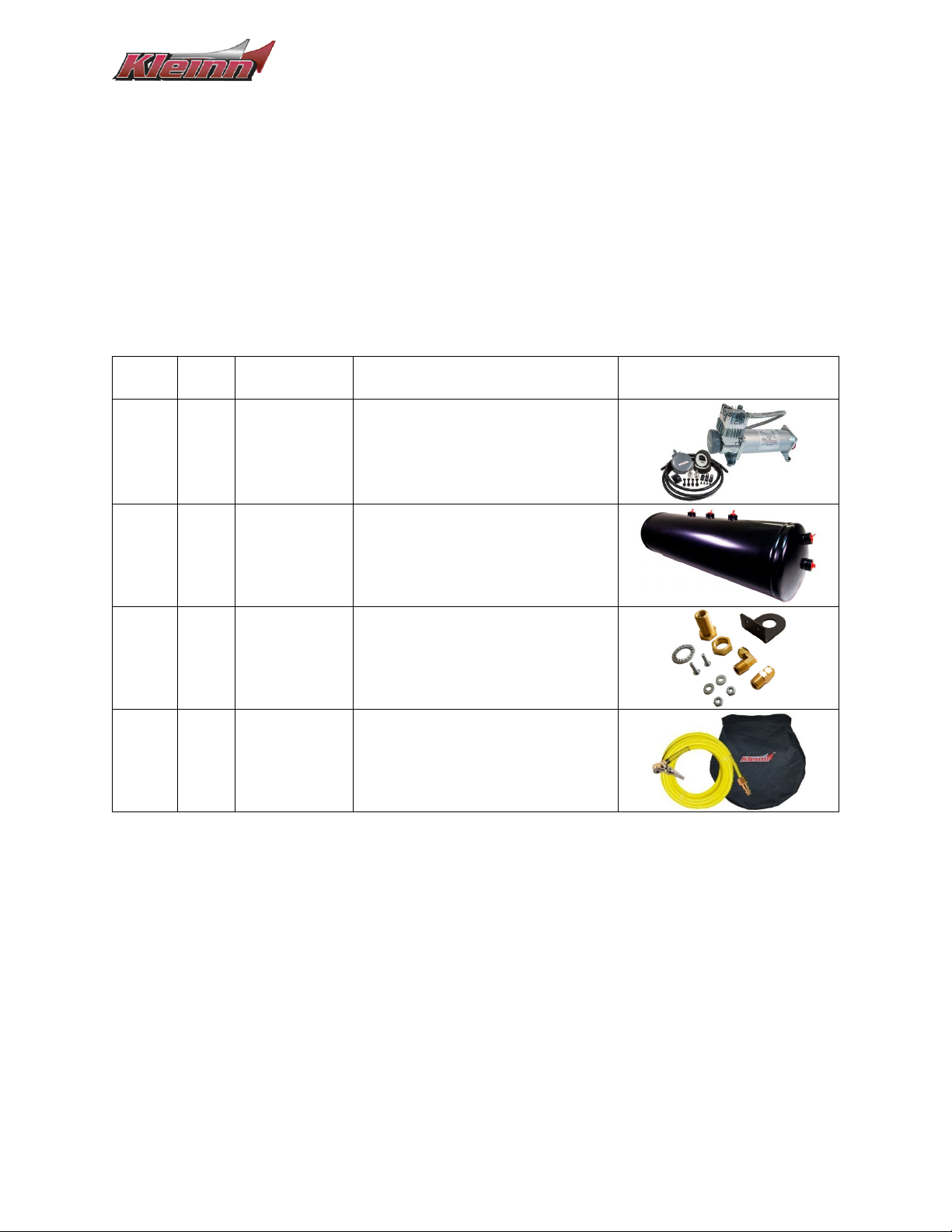
5.1. Primary Kit Components
NOTE: Items in this section may come in their own packages which may include additional items,
hardware, or documentation.
Item
No.
Qty Part No. Description Picture
1.
1 6450RC 150 PSI Waterproof Air Compressor
Kit
2.
1 6353RT 2.6 Gal. Air Tank, 9-Port
3.
1 1302 Quick Disconnect Air Relocation Kit
NOTE: May be located within INF-1 Kit
4.
1 INF-1 Tire Inflator Kit

Install Guide GMHD20-OBA
Page | 8 Revision: A
5.2. Fittings & Related Items
Item
No.
Qty Part No. Description Picture
F1
1 51414F ¼” NPT Female to ¼” Compression
F2
1 51414L ¼” NPT Male to ¼” Compression,
Elbow
F3
1 51414NPTL ¼” NPT Male to ¼” NPT Female,
Elbow
F4
1 52175 175 PSI Pop-Off Safety Valve
F5
4 50040 ¼” NPT Male, Hex Plug
F6
1 52835 ¼” NPT Male Drain Plug
F7
1 2151 Pressure switch,
110 PSI On – 145 PSI Off
F8
12 ft
&
12 ft
25014 1/4" Air Tubing
NOTE: May be located within INF-1 Kit
F9
2 JUICE NPT Thread Sealant
Install Guide GMHD20-OBA
Page | 9 Revision: A
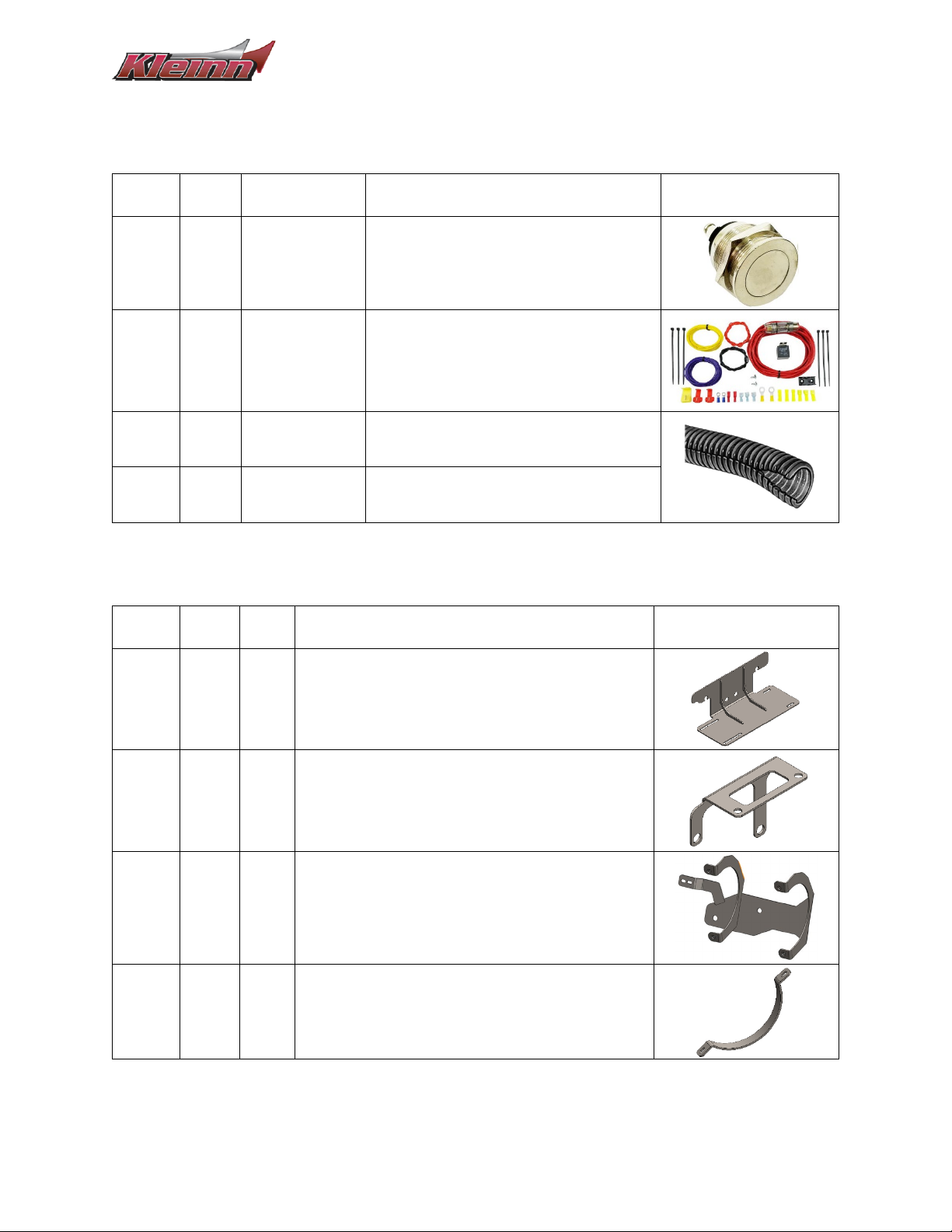
5.3. Electrical Components & Related Items
Item
No.
Qty Part No. Description Picture
-
1 320 Momentary Switch, NO
-
1 N/A Wire Kit
-
30 ft N/A 3/8” Loom Pack
-
10 ft N/A 1/4" Loom Pack
5.4. Mounting Brackets
Item
No.
Qty
Part
No.
Description Picture
-
1 - Compressor Bracket
-
1 - Module Relocation Bracket
-
1 - Tank Bracket
-
2 - Tank Strap

Install Guide GMHD20-OBA
Page | 10 Revision: A
5.5. Hardware & Related Items
Print out the hardware sheets at the end of this section at 100% Scale to facilitate hardware
identification.
Item
No.
Qty Hardware Size Description Picture
H1
4 M10 x 1.5, 100mm
Length Hex Head Bolt
H2
4 M10 x 1.5 Hex Nut
H3
8
M10
Flat Washer
H4
4 Split-Lock Washer
H5
6 1/4"-20, 1” Length Socket Head Cap Screw
H6
8
1/4"
SAE Washer
H7
6 Split-Lock Washer
H8
2 ft - Narrow U-Strip, Rubber *
H9
2 1/4"-20 Hex Nut
*Not Illustrated on the Scale Sheets

NOTE:
SCALE IMAGES OF PRE-PACKAGED HARDWARE INCLUDED WITH
THE COMPRESSOR ARE NOT ILLUSTRATED.
SCALE IMAGES OF UNIQUE & EASILY IDENTIFIABLE HARDWARE ARE
NOT ILLUSTRATED.
THIS DOCUMENT IS DESIGNED TO BE VIEWED / PRINTED AT 100% OR
"ACTUAL SIZE".
ITEM
#
QTY
SCALE IMAGE
H1
4
H2
4
H3
8
H4
4
H5
6
H6
8
H7
6
H8
2 FT
ITEM NOT ILLUSTRATED
H9
2
5/4/2023
SCALE HARDWARE
GMHD20-OBA
1

Install Guide GMHD20-OBA
Page | 11 Revision: A
6. Recommended Routing of Air Tubing & Wire
The below figures are a recommendation of the routing paths for both the air tubing & the wiring. Verify
routing paths, wire lengths, & fuse/relay component locations before cutting the included wire.
Reference Section 9 (On-Vehicle Electrical Installation) for a detailed electrical connection guide.
Figure 2- Recommended Air Tubing Routing
Figure 3- Recommended Electrical Routing (Grounding Points Not Shown)

Install Guide GMHD20-OBA
Page | 12 Revision: A
7. Bench Assembly
7.1. Rubber Trim – Cutting & Installation
1. Cut hardware H8 & run the channel along the curved portions of the tank bracket as shown
below.
Figure 4- Rubber Trim Installation
Install Guide GMHD20-OBA
Page | 13 Revision: A
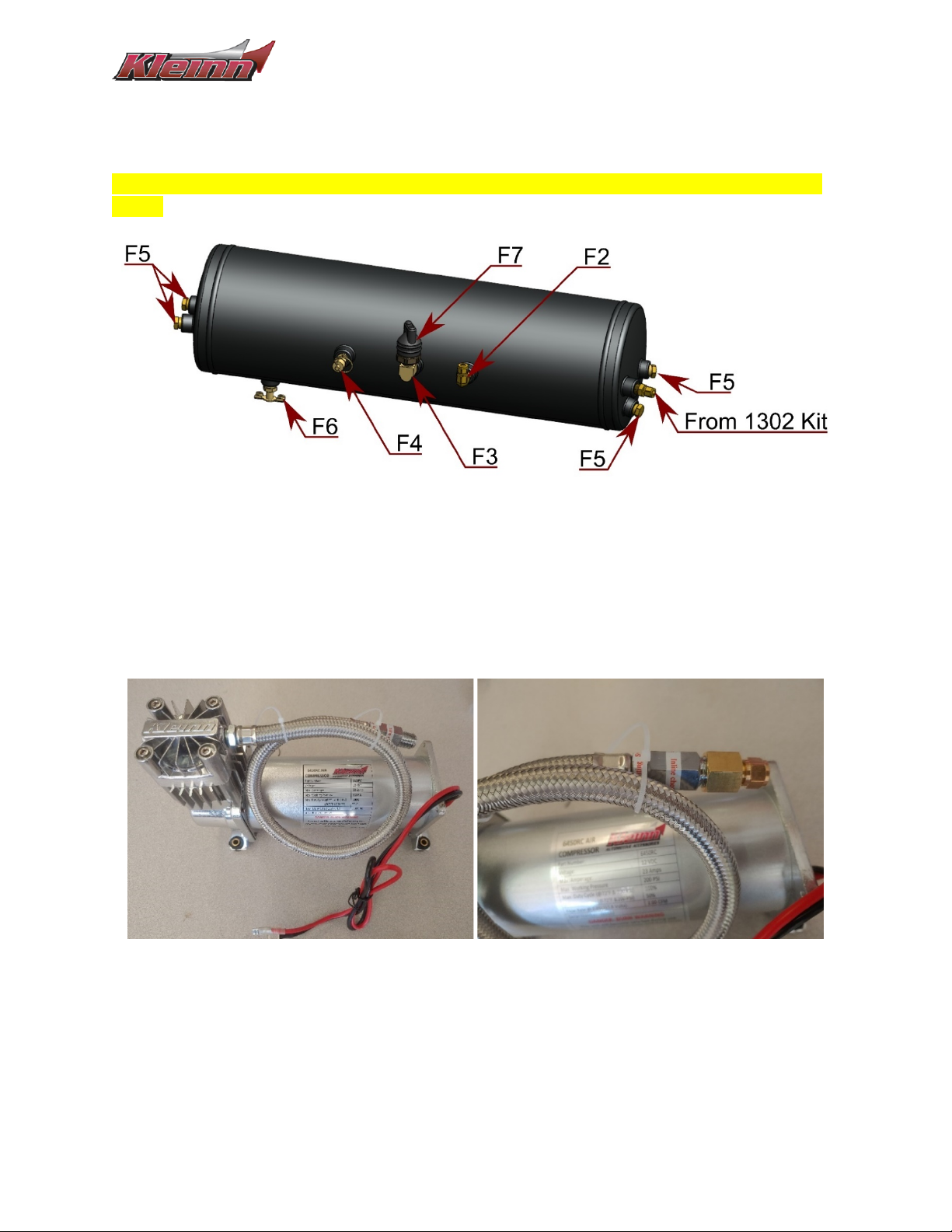
7.2. Air Tank – Fitting Installation
Using KLEINN Juice, install the associated fittings onto the air tank as shown in the below figure.
Hand tighten the fittings, then further tighten 1/4 - 1/2 turn (or as needed) to match the orientation
shown.
Figure 5- Air Tank Fittings, Orientation & Location
7.3. Compressor – Fitting Installation
1. Using KLEINN Juice, apply 2-3 drops of the thread sealant onto the male threads of the
compressor check valve.
NOTE: Ensure the check valve air outlet hole does not get covered by the JUICE.
2. Install & hand tighten fitting F1 onto the threads and tighten 1/4 to 1/2 turn.
Figure 6- Compressor Fitting Installation
3. Install the 1/4" air tubing onto the compression fitting.
4. Install the inlet filter directly onto the air compressor, or, following the instructions included
with the compressor, route & install the snorkel kit as desired.
7.4. INF-1 – Fitting Installation
1. Use a few drops of the KLEINN Juice & install the INF-1 Fittings to the hose as desired.

Install Guide GMHD20-OBA
Page | 14 Revision: A
8. On-Vehicle Assembly
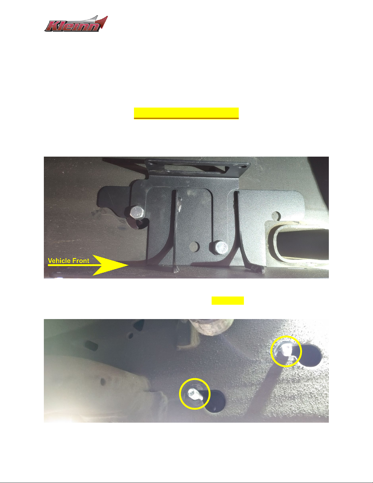
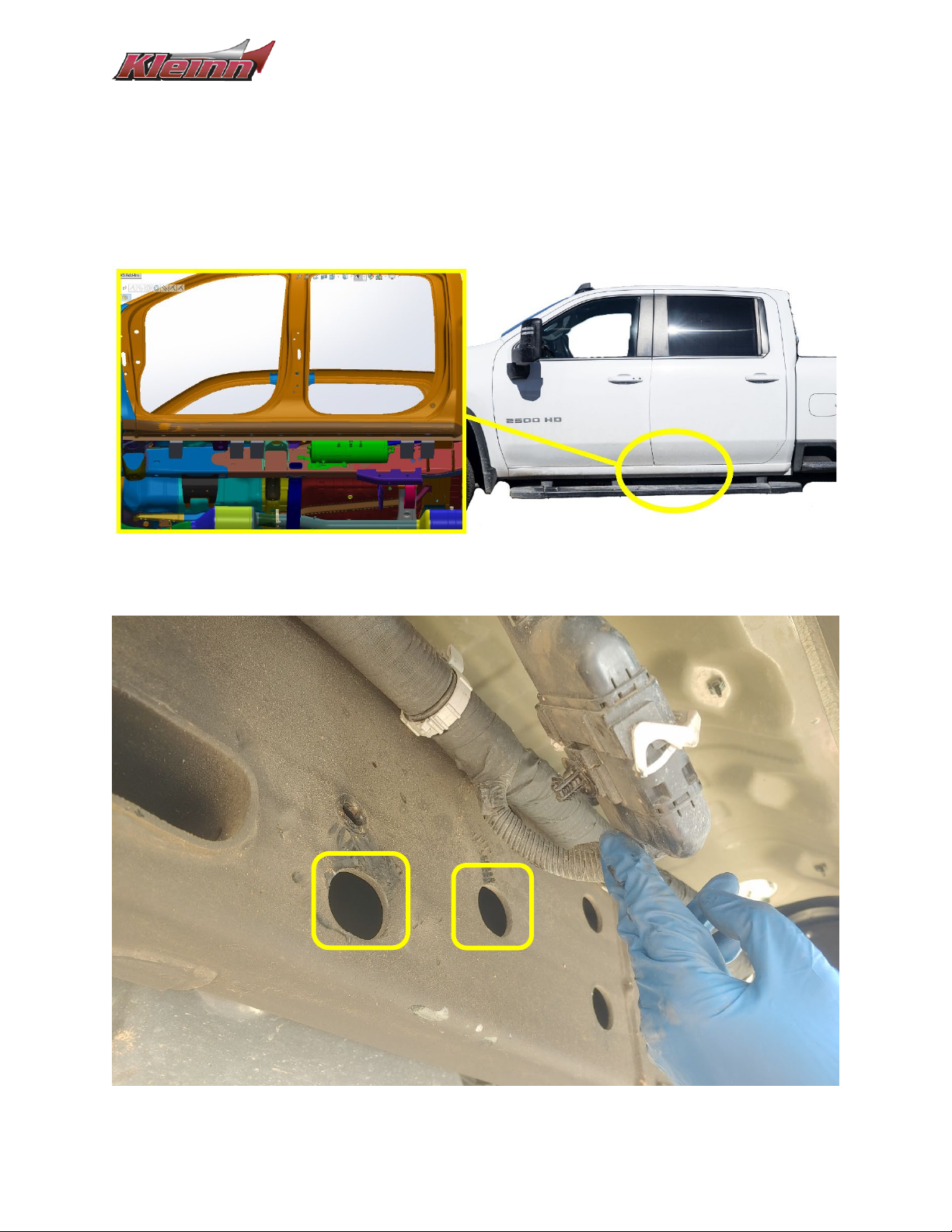
8.1. Compressor Installation
The compressor is located on the passenger side of the vehicle, on the outside frame rail, slightly to the
rear of the seam of the front & rear doors.
Figure 7- Compressor Install Location, Passenger Side
Figure 8- Compressor Bracket, Mounting Points (Above w/o Module, Below w/ Module)
Install Guide GMHD20-OBA
Page | 15 Revision: A
NOTE: If your vehicle has the module that obstructs the compressor bracket location, you will need to use
the included module relocation bracket when installing the compressor bracket.
1. If required, remove the computer module & the frame mounted U-Nuts from the frame rail.
NOTE: Proceed to the following installation steps based on Diesel or Gasoline Engines
For Gasoline Engines Only:
2. Place the compressor bracket onto the correct position on the frame rail and insert hardware H1
through the compressor bracket mounting holes & (if required), through the module relocation
bracket as shown below.
Figure 9- Compressor Bracket Installation, Outside Frame Rail
3. Fully secure the bracket into position using hardware in the order H3, H4 & H2. Ensuring the
threaded section of the bolts are in the upper-left slot of the frame rail as shown below.
Figure 10- Compressor Bracket Installation, Inside Frame Rail
Install Guide GMHD20-OBA
Page | 16 Revision: A
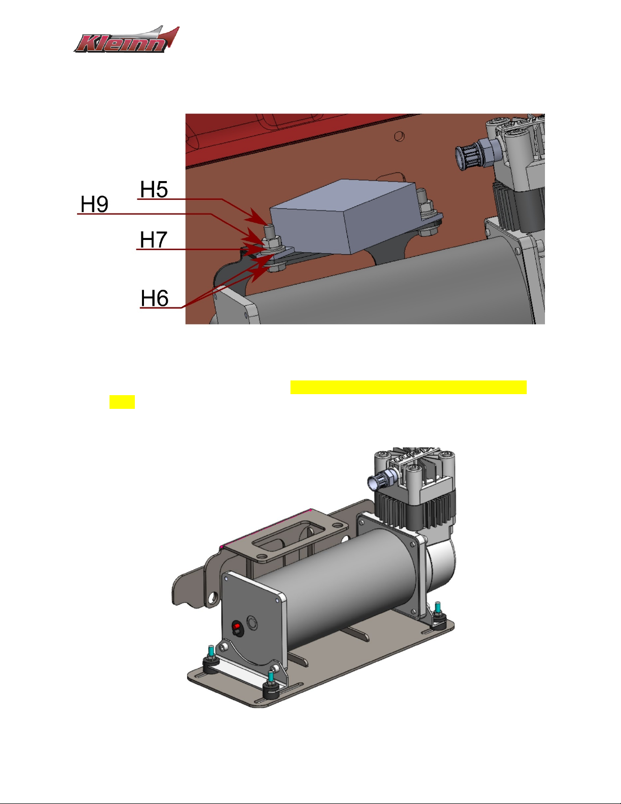
4. If required, use hardware H5, H6, H7 & H9 to install the computer module onto the Module
Relocation Bracket as shown below.
Figure 11- Computer Module, Hardware Stacking Order
5. Place the compressor onto the bracket. The compressor head should be towards the vehicle
front.
6. Use the hardware included in the compressor box & fasten the compressor from the underside
of the bracket as shown below.
Figure 12- Compressor Mounted, Compressor & Hardware Orientation
Install Guide GMHD20-OBA
Page | 17 Revision: A
For Diesel Engines Only:
2. Remove the crossmember’s rightmost bolt that is recessed within the frame rail.
3. Place the compressor bracket onto the correct position on the frame rail and insert hardware H1
through the rightmost bracket mounting hole & (if required), through the module relocation
bracket as shown below.
Figure 13- Compressor Bracket Installation 1, Diesel
4. Allow the bracket(s) to hang & remove the leftmost bolt that is recessed within the frame rail.
5. Slide the compressor bracket into position & insert hardware H1 through the leftmost bracket
mounting hole & (if required), through the module relocation bracket as shown below.
NOTE: To achieve proper alignment, it may be necessary to slightly lift the wiring loom anchor post if it
contacts the compressor bracket.
Figure 14- Compressor Bracket Installation 2, Diesel
Install Guide GMHD20-OBA
Page | 18 Revision: A
6. Fully tighten hardware H1 & (if required), attach the module to the relocation bracket using
hardware H5, H6, H7 & H9 as shown in the above Figure 11.
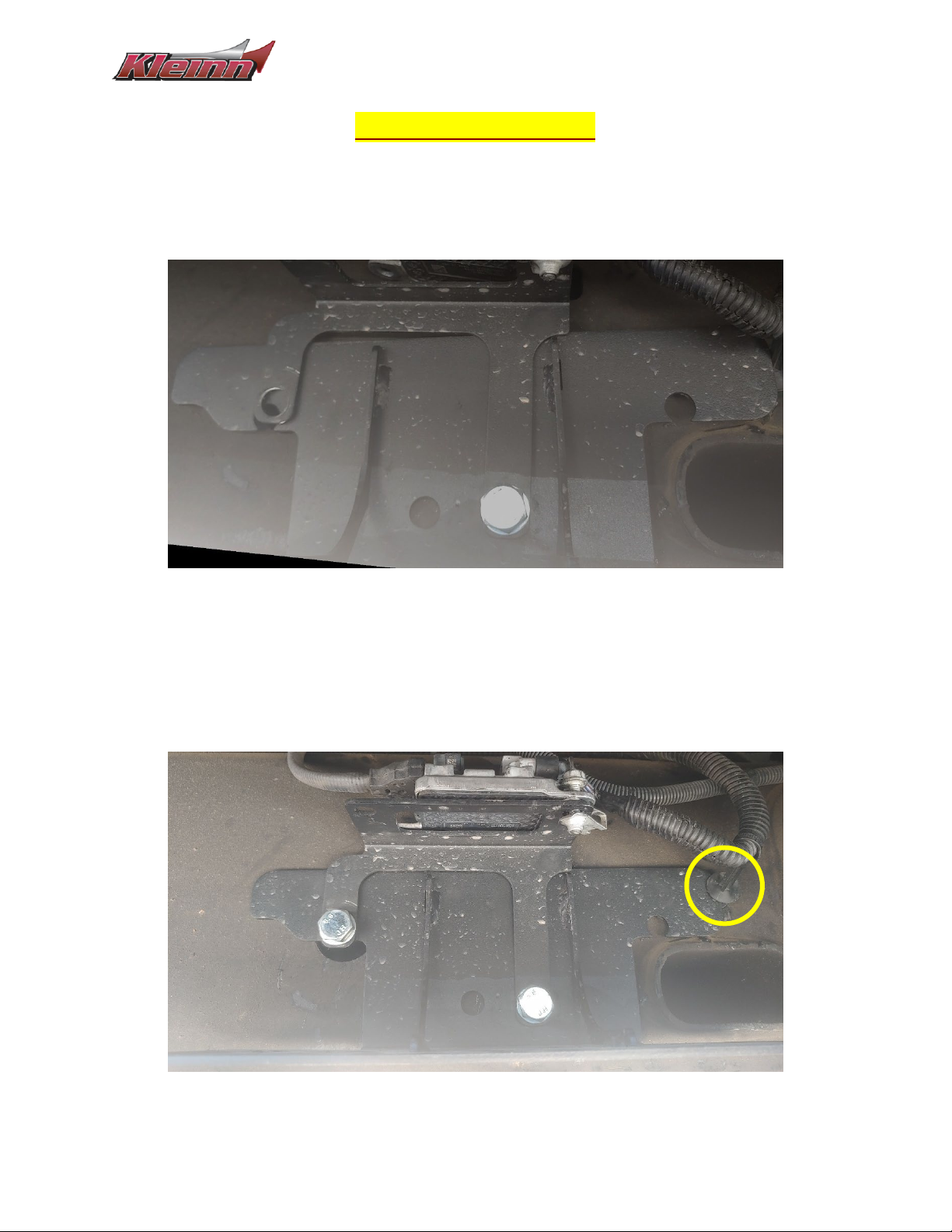
8.2. Tank Installation
The air tank mounts to the outside frame rail (driver side) that is in line with the rear door.
Figure 15- Tank Install Location, Driver Side
Figure 16- Tank Frontmost Bracket, Mounting Point
Install Guide GMHD20-OBA
Page | 19 Revision: A
1. Pry off the electrical connector from the frame rail and move aside to gain access to the tank
bracket mounting location shown in the above figure.
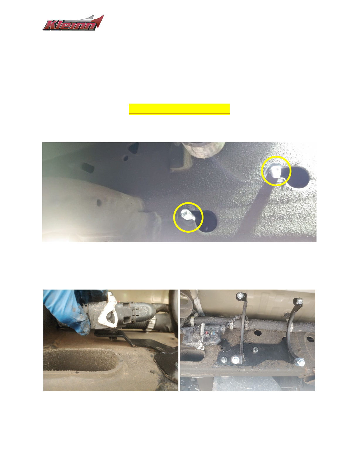
For Gasoline Engines Only:
2. Use hardware H1 to place the tank bracket onto the frame rail. Ensure the threaded portion of
the bolts are in the upper slots of the frame as shown below.
Figure 17- Tank Bracket Installation, Inside Frame Rail
3. Fully secure the bracket into position using hardware H3, H4 & H2,
4. Route the connector wiring and secure the connector to one of the slots on the tab of the tank
bracket as shown below.
Figure 18- Tank Bracket Installation, Connector Placement
Table of contents
Other Kleinn Automobile Accessories manuals


Popular Automobile Accessories manuals by other brands


ULTIMATE SPEED
ULTIMATE SPEED 279746 Assembly and Safety Advice

SSV Works
SSV Works DF-F65 manual

ULTIMATE SPEED
ULTIMATE SPEED CARBON Assembly and Safety Advice

Witter
Witter F174 Fitting instructions

WeatherTech
WeatherTech No-Drill installation instructions

TAUBENREUTHER
TAUBENREUTHER 1-336050 Installation instruction