1213118-IN01-C -2-
INSTALLATION GUIDELINE
in
Toll Free 1800 103 2244
1. Prepare the Site :-
• Rough-in the supplies & the drain piping. For dimensions, Refer Fig.#2.
• Install 1/2" water supply lines & 1-1/4" drain piping according to the roughing-in information.
• Install sufficient backing behind the finished wall to provide a secure material for the anchoring devices.
NOTE :- The Angle-Valve handles cannot extend more than 76mm (3") from the finished wall when in open position. This will
ensure the handles will not touch the pedestal when fully open.
Important Notice for Care, Cleaning & Daily use
To keep your lavatory looking new, make sure you rinse it out thoroughly after each use.
DO NOT USE ABRASIVES on this product, as they will scratch & ruin the surface.
Stubborn stains, paint, or tar can be removed with turpentine or paint thinner.
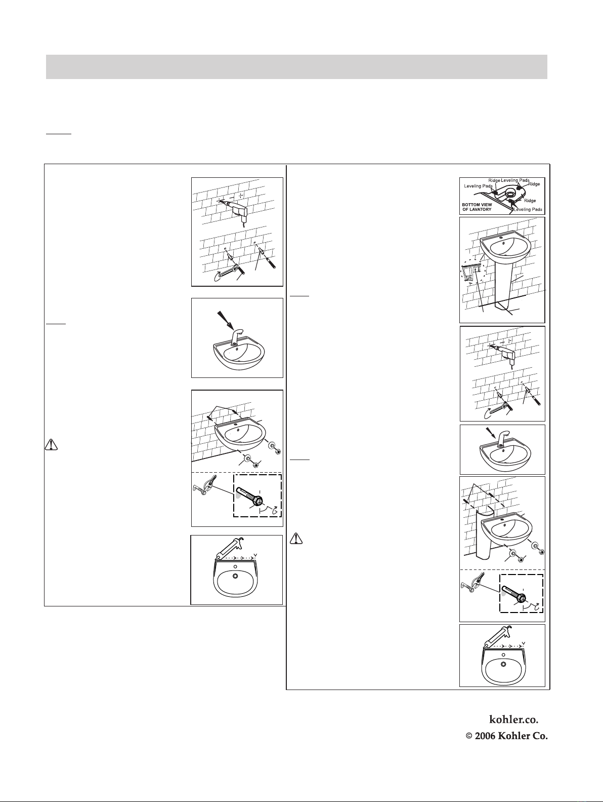
2. Installation of the Lavatory :-
Plastic Washer
Nut
Lavatory
Metal Studs
WALL-MOUNT
CAUTION : Risk of product damage.
Do not over tighten the nut. Over tightening
may cause damage to the product.
Use wrench to tighten 8-10 N-m/ 6-9 turns.
(1 turn = 45°) past finger tight.
• Connect & tighten the bottle trap as per
manufacturer’s instructions. Connect the
hot & cold water supplies to the faucet.
• Drill two 14mm Anchor holes on the wall as
shown in the Rough-in diagram.
• Insert the plastic anchors (provided) in two
holes.
• Insert the metal studs (provided) into these
plastic anchors using an adjustable wrench.
• Ensure that at least 70 mm (approx.) of each
stud should remain exposed from the wall.
Refer Fig. #3
Ø
Plastic Anchors
Metal Studs
• Install the faucet & drain to the lavatory
according to the manufacturer’s instructions.
so the metal studs extend through the
lavatory holes.
• Level the lavatory.
• Install the plastic washer & nut (provided)
& tighten suitably.
• Carefully place the lavatory against the wall,
NOTE :- Do not fully tighten slip-joint drain
connections at this time.
Refer Fig. #4
• Evenly p
surface of the lavatory touching the wall.
• Clean the lavatory top.
Refer Fig. #6
ut the sealant around the mounting
Metal Studs
Lavatory
FULL-PEDESTAL
• Apply two self-adhesive levelling pads (provided)
to each of the three ridges in the bottom recess of the
lavatory. Refer Fig. #7
• Mark the centerline on the floor with a pencil.
• Position the pedestal on the floor centerline location.
Refer to the roughing-in dimensions for correct
placement.
• Carefully set the lavatory on the pedestal.
• Move the pedestal as required to ensure proper
fit in the desired location.
• Level the lavatory. Use additional self-adhesive
levelling pads as required to level the lavatory.
NOTE :-The lavatory must be supported by the
pedestal.
• Check the lavatory placement.
• Mark the center of each anchoring hole on the wall.
• Carefully remove the lavatory from the pedestal. Then
move the pedestal from the area.
Refer Fig. #8
• Ø
on the wall.
• Insert the plastic anchors in two holes.
• Insert the metal studs (provided) into these plastic
anchors using an adjustable wrench.
• Ensure that at least 70 mm (approx.) of each stud
should remain exposed from the wall.
Refer Fig. #9
Drill two 14mm Anchor holes at the marked location
•
•
studs extend through the lavatory holes.
• Level the lavatory.
• Install the washer & nut & tighten suitably.
Place the pedestal to its original location.
Set the lavatory on the pedestal so the metal
Pedestal
Mark Floor
Here
Center of
Anchoring Holes
CAUTION : Risk of product damage.
Do not over tighten the nut. Over tightening
may cause damage to the product.
Use wrench to tighten 8-10 N-m/ 6-9 turns.
(1 turn = 45°) past finger tight.
•
instructions. Connect the hot & cold water supplies
to the faucet.
Connect & tighten the trap as per manufacturer’s
•
to the manufacturer’s instructions.
Install the faucet & drain to the lavatory according
NOTE :- Do not fully tighten slip-joint drain
connections at this time.
Refer Fig. #10
Plastic
Anchors
Metal Studs
•
surface of the lavatory touching the wall.
• Clean the lavatory top.
Refer Fig. #12
Evenly put the sealant around the mounting
SERVICE PARTS (Supplied with the Product)
A. Hardware Kit 1213117
B. Levelling Pads 63069
Nut
Plastic Washer
3
4
5
6
7
8
9
10
11
12
45°
6-9 turns (45 ) allowed past finger tight ° each
Refer Fig. #5
Refer Fig. #11
45°
6-9 turns (45 ) allowed past finger tight ° each
*
* Installation doesn't allow use of any tool other than standard wrench.
For this reason, split turns have been mentioned rather than full turns.
*


