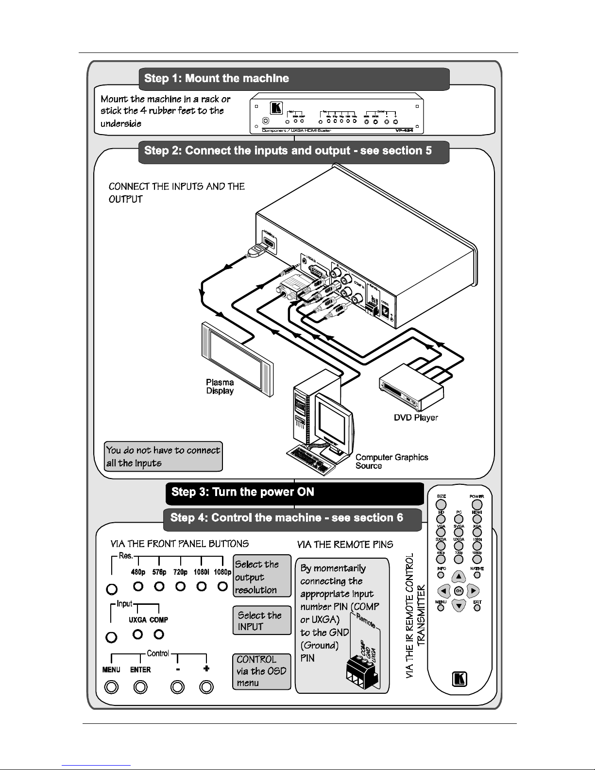
Kramer VP-434 User manual

Kramer Electronics, Ltd.
USER MANUAL
Model:
VP-434
Component / UXGA HDMI Scaler

Contents
i
Contents
1
Introduction 1
2
Getting Started 1
2.1
Quick Start 1
3
Overview 3
3.1
About HDMI 3
3.2
Recommendations for Best Performance 5
4
Your VP-434 Component / UXGA HDMI Scaler 5
5
Connecting the VP-434 Component / UXGA HDMI Scaler 7
5.1
Connecting the Contact Closure Remote Control PINs 9
6
Controlling the VP-434 10
6.1
Controlling via the Front Panel Buttons 10
6.2
Using the CONTROL Buttons 10
6.2.1
The MAIN MENU 11
6.2.2
The OSD Menu 11
6.3
Controlling via the Infra-Red Remote Control Transmitter 12
7
Technical Specifications 13
Figures
Figure 1: VP-434 Component / UXGA HDMI Scaler – Front and Rear View 5
Figure 2: Connecting the VP-434 Component / UXGA HDMI Scaler 8
Figure 3: Connecting the Contact Closure Remote Control PINs 9
Figure 4: Infra-Red Remote Control Transmitter 12
Tables
Table 1: VP-434 Component / UXGA HDMI Scaler Front Panel Features 6
Table 2: VP-434 Component / UXGA HDMI Scaler Rear Panel Features 6
Table 3: The MAIN MENU Features 11
Table 4: The SETUP Menu Features 11
Table 5: Infra-Red Remote Control Transmitter Functions 12
Table 6: Technical Specifications of the VP-434 Component / UXGA HDMI Scaler 13

Introduction
1
1 Introduction
Welcome to Kramer Electronics! Since 1981, Kramer Electronics has been
providing a world of unique, creative, and affordable solutions to the vast
range of problems that confront the video, audio, presentation, and
broadcasting professional on a daily basis. In recent years, we have
redesigned and upgraded most of our line, making the best even better! Our
500-plus different models now appear in eight groups
1
that are clearly defined
by function.
Congratulations on purchasing your Kramer VP-434
Component / UXGA
HDMI Scaler. This product, which incorporates HDMI™ technology, is ideal
for:
Projection systems in conference rooms, boardrooms, hotels and churches
Home theater up-scaling
The package includes the following items:
VP-434
Component / UXGA HDMI Scaler
Power adapter (12V DC input)
Infra red remote control transmitter
This user manual
2
2 Getting Started
We recommend that you:
Unpack the equipment carefully and save the original box and packaging
materials for possible future shipment
Review the contents of this user manual
Use Kramer high performance high resolution cables
3
2.1 Quick Start
This Quick start chart summarizes the basic setup and operation steps.
1 GROUP 1: Distribution Amplifiers; GROUP 2: Video and Audio Switchers, Matrix Switchers and Controllers; GROUP 3:
Video, Audio, VGA/XGA Processors; GROUP 4: Interfaces and Sync Processors; GROUP 5: Twisted Pair Interfaces;
GROUP 6: Accessories and Rack Adapters; GROUP 7: Scan Converters and Scalers; and GROUP 8: Cables and Connectors
2 Download up-to-date Kramer user manuals from the Internet at this URL: http://www.kramerelectronics.com
3 The complete list of Kramer cables is on our Web site at http://www.kramerelectronics.com

KRAMER: SIMPLE CREATIVE TECHNOLOGY
Getting Started
2

Overview
3
3 Overview
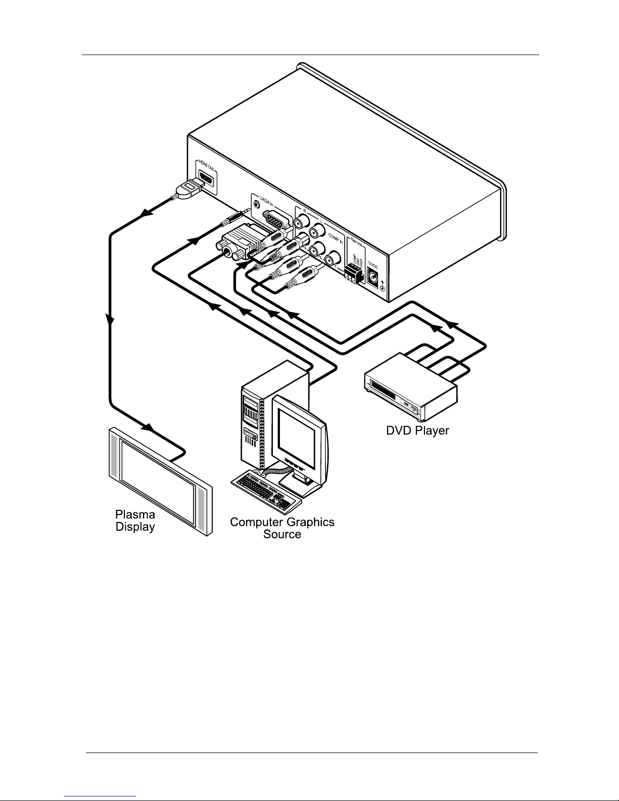
The Kramer VP-434 is a high quality component video/UXGA (computer video
graphics) to HDMI scaler. It accepts one of two inputs: either component video
1
on RCA connectors or computer video graphics on a 15-pin HD computer
graphics video connector (selected via a front panel selector button or via the
Remote contact closure switch). It scales the video, embeds the audio, and
outputs the signal to the HDMI output.
The VP-434
Component / UXGA HDMI Scaler:
Is HDTV compatible and the resolution can be scaled up to 480p, 576p,
720p, 1080i or 1080p via a front panel selector button
2
Has analog audio inputs for the COMP and UXGA sources
Comes with an On-Screen Display (OSD) for easy setup and adjustment,
accessible via the IR remote control and via the front-panel buttons
Has a non-volatile memory that retains the last settings used
Is housed in a desktop sized enclosure and is 12VDC fed
Control your VP-434:
Directly, via the front panel push buttons
Remotely, from the infra-red remote control transmitter
Remotely, from the Remote contact closure switch
3.1 About HDMI
High-Definition Multimedia Interface (HDMI) is an uncompressed all-digital
3
audio/video interface, widely supported in the entertainment and home cinema
industry. It delivers the maximum high-definition image and sound quality in use
today. Note that Kramer Electronics Limited is an HDMI Adopter
4
and an HDCP
Licensee
5
.
1 Also known as Y, Pb, Pr, Y, Cb, Cr and YUV
2 Other resolutions can be selected via the OSD menu. These include: 1080i, 1080p, 576i, 576p, 720p, 1080i, 1080p, WXGA,
WSXGA, WUXGA, NATIVE, VGA, SVGA, XGA, SXGA, UXGA, 480i, 480p
3 Ensuring an all-digital rendering of video without the losses associated with analog interfaces and their unnecessary digital-
to-analog conversions
4 See http://www.hdmi.org/about/adopters_founders.asp
5 See http://www.digital-cp.com/list/

KRAMER: SIMPLE CREATIVE TECHNOLOGY
Overview
4
In particular, HDMI
1
:
Provides a simple
2
interface between any audio/video source, such as a
set-top box, DVD player, or A/V receiver and video monitor, such as a
digital flat LCD / plasma television (DTV), over a single lengthy
3
cable
Supports standard, enhanced, high-definition video, and multi-channel
digital audio
4
on a single cable
Transmits all ATSC HDTV standards and supports 8-channel digital audio,
with bandwidth to spare to accommodate future enhancements and
requirements
Benefits consumers by providing superior, uncompressed digital video
quality via a single cable
5
, and user-friendly connector
Is backward-compatible with DVI (Digital Visual Interface)
Supports two-way communication between the video source (such as a
DVD player) and the digital television, enabling new functionality such as
automatic configuration and one-button play
HDMI has the capacity to support existing high-definition video formats
(720p, 1080i, and 1080p/60), standard definition formats such as NTSC or
PAL, as well as 480p and 576p.
1 HDMI, the HDMI logo and High-Definition Multimedia Interface are trademarks or registered trademarks of HDMI
licensing LLC
2 With video and multi-channel audio combined into a single cable, the cost, complexity, and confusion of multiple cables
currently used in A/V systems is reduced
3 HDMI technology has been designed to use standard copper cable construction at up to 15m
4 HDMI supports multiple audio formats, from standard stereo to multi-channel surround-sound. HDMI has the capacity to
support Dolby 5.1 audio and high-resolution audio formats
5 HDMI provides the quality and functionality of a digital interface while also supporting uncompressed video formats in a
simple, cost-effective manner

Your VP-434 Component / UXGA HDMI Scaler
5
3.2 Recommendations for Best Performance
To achieve the best performance:
Connect only good quality connection cables, thus avoiding interference,
deterioration in signal quality due to poor matching, and elevated noise-
levels (often associated with low quality cables)
Avoid interference from neighboring electrical appliances and position
your Kramer VP-434 away from moisture, excessive sunlight and dust
Caution – No operator-serviceable parts inside unit.
Warning – Use only the Kramer Electronics input power
wall adapter that is provided with this unit
1
.
Warning – Disconnect power and unplug unit from wall
before installing or removing device or servicing unit.
4 Your VP-434 Component / UXGA HDMI Scaler
Figure 1, Table 1 and Table 2 define the VP-434
Component / UXGA HDMI
Scaler:
Figure 1: VP-434 Component / UXGA HDMI Scaler – Front and Rear View
1 For example: model number AD2512C, part number 2535-000251

KRAMER: SIMPLE CREATIVE TECHNOLOGY
Your VP-434 Component / UXGA HDMI Scaler
6
Table 1: VP-434 Component / UXGA HDMI Scaler Front Panel Features
# Feature Function
1 IR Receiver Receives signals from the remote control transmitter
2 Selector Button Press to select the UXGA input or the COMP input
3 UXGA Indicator LED Lights when the UXGA input is selected
4
Input
COMP Indicator LED Lights when the COMP input is selected
5 Selector Button Press to select the resolution: 480p, 576p, 720p, 1080i or 1080p
6 480p Indicator LED Lights when the 480p resolution is selected
7 576p Indicator LED Lights when the 576p resolution is selected
8 720p Indicator LED Lights when the 720p resolution is selected
9 1080i Indicator LED Lights when the 1080i resolution is selected
10
Res.
1080p Indicator LED Lights when the 1080p resolution is selected
11 MENU Button Displays the OSD menu (see section 6.2)
12 ENTER Button Press to accept changes and change the SETUP parameters
1
13 - Button Press to move down the menu list
1
14
Control
+ Button Press to move up the menu list values
1
Table 2: VP-434 Component / UXGA HDMI Scaler Rear Panel Features
# Feature Function
15 HDMI Out Connector Connects to the HDMI acceptor
16 3.5mm Mini Jack Connector
Connects to the analog unbalanced stereo audio signal
source
17
UXGA In
UXGA HD15F Connector Connects to the UXGA source
18 L RCA Connector
19 R RCA Connector
Connect to the left and right analog unbalanced stereo
audio source (of the COMP source)
20 P
R
RCA Connector
21 P
B
RCA Connector Connects to the component video source
2
22
COMP In
YRCA Connector
23 Remote Contact Closure Pins Connects to a contact closure switch (see section 5.1)
24 12 VDC +12V DC connector for powering the unit
1 See section 6.2.2
2 For component video, connect all three connectors: Y, Cb, Cr (also known as YUV)

Connecting the VP-434 Component / UXGA HDMI Scaler
7
5 Connecting the VP-434 Component / UXGA HDMI Scaler
To connect
1
your VP-434, as illustrated in the example in Figure 2, do the
following
2
:
1. Connect a component video source (for example, a DVD player) to the
COMP In Y, Pb, Pr, RCA connectors, and to the COMP In L and R audio
RCA connectors.
2. Connect a computer graphics source to the UXGA In 15-pin HD computer
graphics video connector, and to the UXGA In audio 3.5mm mini jack
connector.
3. Connect the HDMI Out connector to an HDMI acceptor (for example, a
plasma display).
4. Connect the 12V DC power adapter to the power socket and connect the
adapter to the mains electricity (not shown in Figure 2).
1 You do not have to connect all the inputs, connect only those that are required
2 Switch OFF the power on each device before connecting it to your VP-434. After connecting your VP-434, switch on its
power and then switch on the power on each device

KRAMER: SIMPLE CREATIVE TECHNOLOGY
Connecting the VP-434 Component / UXGA HDMI Scaler
8
Figure 2: Connecting the VP-434 Component / UXGA HDMI Scaler

Connecting the VP-434 Component / UXGA HDMI Scaler
9
5.1 Connecting the Contact Closure Remote Control PINs
The contact closure pins operate in a similar way to the Input selector button.
Using the contact closure remote control you can select the COMP or the
UXGA input. To do so, temporarily connect the required input
1
pin on the
REMOTE terminal block connector to the GND (Ground) pin, as Figure 3
illustrates.
DO NOT connect more than one PIN to the GND PIN at the same time
To select COMP,
connect the
COMP PIN to the
GND PIN
To select UXGA,
connect the
UXGA PIN to the
GND PIN
Figure 3: Connecting the Contact Closure Remote Control PINs
1 COMP or UXGA

KRAMER: SIMPLE CREATIVE TECHNOLOGY
Controlling the VP-434
10
6 Controlling the VP-434
The VP-434 can be controlled directly via the front panel buttons (see section
6.1), via the OSD menu (see section 6.2), and/or remotely from the infra-red
remote control transmitter (see section 6.3).
6.1 Controlling via the Front Panel Buttons
The VP-434 includes the following front panel buttons:
An Input selector button for selecting the required input (UXGA or
COMP)
A resolution (Res.) button for selecting the desired resolution
Control buttons, including the MENU, ENTER, + and – buttons
6.2 Using the CONTROL Buttons
The CONTROL buttons let you control the VP-434 via the OSD menu. Press
the:
MENU button to enter the menu
1
ENTER button to accept changes and to change the menu settings
+ and – buttons to move through the OSD menu, which is displayed on
the video output
On the OSD menu, select EXIT to exit the menu.
1 The default timeout is set to 10 seconds

Controlling the VP-434
11
6.2.1 The MAIN MENU
Table 3 defines the MAIN MENU features and functions.
Table 3: The MAIN MENU Features
Mode Function
CONTRAST Set the contrast (0 to 100)
BRIGHTNESS Set the brightness (0 to 100)
FINETUNE Set the hue, saturation and sharpness (0 to 100)
COLOR Set the red, green and blue shades (0 to 100)
SIZE Select the size of the display: full, overscan, underscan, letter box, panscan
OUTPUT Select the output resolution from the menu:
Appears as: Output resolution: Appears as: Output resolution:
1080I60 1080i @60Hz NATIVE
1
1080P60 1080p @60Hz VGA 640x480
576I 576i SVGA 800x600
576P 576p XGA 1024x768
720P50 720p @50Hz SXGA 1280x1024
1080I50 1080i @50Hz UXGA 1600x1200
1080P50 1080p @50Hz 480I 480i
WXGA 1280x720 480P 480p
WSXGA 1680x1050 720P60 720p @50Hz
WUXGA 1920x1200
OSD Set the OSD parameters: H POSITION, V POSITION, TIMER, BACKGROUND (see
section 6.2.2)
FACTORY RESET Resets to the default parameters (resolution is set to VGA
2
)
INFORMATION Displays the source, the input resolution, the output resolution and the software version
EXIT Select to exit the menu
6.2.2 The OSD Menu
Table 4 defines the OSD menu.
Table 4: The SETUP Menu Features
Parameter Function
H POSITION Sets the horizontal position of the OSD (from 0 to 100)
V POSITION Sets the vertical position of the OSD (from 0 to 100)
TIMER Sets the timeout period in seconds (from 5 to 100). The default timeout is 10 seconds
BACKGROUND
Sets the OSD background between 0 (solid black) and 8 (transparent)
1 Select “NATIVE” to select the output resolution from the EDID of the connected HDMI monitor
2 If you cannot see the display after factory reset, use the front panel Res. button to set the correct resolution

KRAMER: SIMPLE CREATIVE TECHNOLOGY
Controlling the VP-434
12
6.3 Controlling via the Infra-Red Remote Control Transmitter
You can control the VP-434 from the infra-red remote control transmitter, as
Figure 4 and Table 5 define:
Table 5: Infra-Red Remote Control
Transmitter Functions
Keys Function
SIZE Set the size of the image displayed
POWER Turn the transmitter ON or OFF
HD Select the component video input
PC Select the UXGA input
HDMI Not used
VGA Set the output resolution to VGA
SVGA Set the output resolution to SVGA
XGA Set the output resolution to XGA
SXGA Set the output resolution to SXGA
UXGA Set the output resolution to UXGA
1080i Set the output resolution to 1080i
480p Set the output resolution to 480p
720p Set the output resolution to 720p
1080p Set the output resolution to 1080p
INFO Displays the selected input, the input
and output resolutions and the firmware
versions on the OSD
NATIVE Select the output resolution from the
EDID of the connected HDMI monitor
Four navigation keys
OK Press to accept changes
MENU Enter the OSD menu
EXIT EXIT the menu
POWER
SIZE
HD PC HDMI
VGA SVGA XGA
SXGA UXGA
1080i
1080p
480p 720p
NATIVE
EXIT
INFO
MENU
OK
Figure 4: Infra-Red Remote Control
Transmitter

Technical Specifications
13
7 Technical Specifications
Table 6: Technical Specifications
1
of the VP-434 Component / UXGA HDMI Scaler
INPUTS: 1 UXGA on an HD15F connector
1 component video on 3 RCA connectors
1 analog unbalanced stereo audio on a 3.5mini jack connector (for the
UXGA input)
2 analog unbalanced stereo audio (left and right) on RCA connectors, 4dBm
nominal
OUTPUT: 1 HDMI connector (HDMI version 1.2, HDCP version 1.1)
OUTPUT RESOLUTIONS:
1080i, 1080p, 576i, 576p, 720p, 1080i, 1080p, WXGA, WSXGA, WUXGA,
NATIVE, VGA, SVGA, XGA, SXGA, UXGA, 480i, 480p
CONTROLS: Front panel buttons, dry contact and infra red remote for menu driven OSD
control
ADDITIONAL
CONTROLS:
Contrast, brightness, hue, saturation and sharpness; red, green and blue;
Resolution, image size
POWER SOURCE: 12V DC, 350mA
DIMENSIONS: 21.5cm x 16.1cm x 4.36cm (8.46” x 6.34” x 1.7”) W, D, H
WEIGHT: 1.1kg (2.43lb.) approx.
ACCESSORIES: Power supply, IR remote control
OPTIONS Rack adapter
1 Specifications are subject to change without notice

KRAMER: SIMPLE CREATIVE TECHNOLOGY
14
LIMITED WARRANTY
WHO IS PROTECTED?
WHAT IS COVERED AND WHAT IS NOT COVERED
WHAT WE WILL PAY FOR AND WHAT WE WILL NOT PAY FOR
HOW YOU CAN GET WARRANTY SERVICE
LIMITATION OF IMPLIED WARRAN TIES
EXCLUSION OF DAMAGES
CAUTION!
Kramer Electronics (hereafter ) warrants this product free from defects in material and workmanship under the
followingterms.
Kramer
HOW LONG IS THE WARRANTY
Labor and parts are warranted for seven years from the date of the first customer purchase.
Only the first purchase customer may enforce this warranty.
Wewillpay labor and material expensesforcovered items.We will notpayfor thefollowing:
The liability of Kramer for any effective productsis limited to the repair or replacement of the product at our option. Kramer shall
notbeliable for:
Thiswarranty gives youspecific legal rights, and you may also have other rights, which varyfrom place toplace.
All products returned to Kramer for service must haveprior approval. This may be obtained from yourdealer.
Thisequipment has been tested todetermine compliance with the requirements of:
EN-50081: "Electromagneticcompatibility(EMC);
genericemissionstandard.
Residential, commercial and lightindustry"
EN-50082: "Electromagneticcompatibility(EMC)genericimmunitystandard.
Part 1: Residential,commercialandlightindustryenvironment".
CFR-47: FCC Rules and Regulations:
Part 15: “Radio frequency devices
Subpart B Unintentional radiators”
Except as below, this warranty covers all defects in material or workmanship in this product. The following are not covered
by the warranty:
1. Any product which is not distributed by Kramer, or which is not purchased from an authorized Kramer dealer. If you are
uncertain as to whether a dealer is authorized, please contact Kramer at one of the agents listed in the Web site
www.kramerelectronics.com.
2. Any product, on which the serial number has been defaced, modified or removed.
3. Damage, deterioration ormalfunction resulting from:
i) Accident, misuse, abuse, neglect, fire, water, lightning or other acts of nature
ii) Product modification, or failure tofollow instructions supplied with the product
iii) Repair orattempted repairby anyonenot authorized byKramer
iv) Anyshipment of the product(claims must be presented tothe carrier)
v) Removalor installationof the product
vi) Anyother cause, which does not relate to a product defect
vii) Cartons, equipment enclosures, cables or accessories usedin conjunctionwiththe product
1. Removal or installationscharges.
2. Costs of initial technical adjustments (set-up), including adjustment of user controls or programming. These costs are the
responsibility of the Kramer dealerfrom whom theproduct was purchased.
3. Shipping charges.
1. To obtain service on you product, you must take or ship it prepaid to any authorized Kramer service center.
2. Whenever warranty service is required, the original dated invoice (or a copy) must be presented as proof of warranty
coverage, and should be included in any shipment of the product. Please also include in any mailing a contact name,
company, address, and a description of the problem(s).
3. For the name of the nearest Kramer authorized service center, consult your authorized dealer.
All implied warranties, including warranties of merchantability and fitness for a particular purpose, are limited in duration to
the length of this warranty.
1. Damage to other property caused by defects inthis product, damages basedupon inconvenience, loss of use of the product, loss
of time, commercial loss; or:
2. Anyother damages, whether incidental, consequentialor otherwise. Some countries maynot allowlimitations on how long an
implied warranty lasts and/or do not allow the exclusion or limitation of incidental or consequential damages, so the above
limitationsand exclusions maynotapplyto you.
Servicing the machines can only be done by an authorized Kramer technician. Any user who makes changes or
modifications to the unit without the expressed approval of the manufacturer will void user authority to operate the
equipment.
Use the suppliedDC power supply tofeed power to the machine.
Please userecommended interconnection cables toconnect the machine to other components.
NOTE:
Part 1:

Kramer Electronics, Ltd.
Web site: www.kramerelectronics.com
P/N: 2900-000346 REV 1
For the latest information on our products and a list of Kramer
distributors, visit our Web site: www.kramerelectronics.com,
where updates to this user manual may be found.
We welcome your questions, comments and feedback.
Caution
Safety Warning:
Disconnect the unit from the power supply before
opening/servicing.
Other manuals for VP-434
1
Table of contents
Other Kramer Media Converter manuals

Kramer
Kramer VP-427H2 User manual

Kramer
Kramer PC-49 User manual

Kramer
Kramer VP-439 User manual

Kramer
Kramer WP-SW2-EN7 User manual

Kramer
Kramer VM-50AN User manual

Kramer
Kramer FC-46H2 User manual

Kramer
Kramer VM-1610 User manual

Kramer
Kramer 6808HDxl User manual

Kramer
Kramer VA-256XL User manual

Kramer
Kramer FC-14 User manual

Kramer
Kramer VS-411UHD User manual

Kramer
Kramer FC-321 User manual

Kramer
Kramer DigiTOOLS VM-2HDMI User manual

Kramer
Kramer VP-510 User manual

Kramer
Kramer KDS-USB2 Kit User manual

Kramer
Kramer VP1 User manual

Kramer
Kramer DigiTOOLS VM-2HDMI User manual

Kramer
Kramer VP-792 User manual

Kramer
Kramer VP-701SC User manual

Kramer
Kramer 465 User manual