Contents
Contents 2
Introduction 4
Getting Started 4
Overview 5
Typical Applications 6
Controlling your KDS-EN7 / KDS-DEC7 6
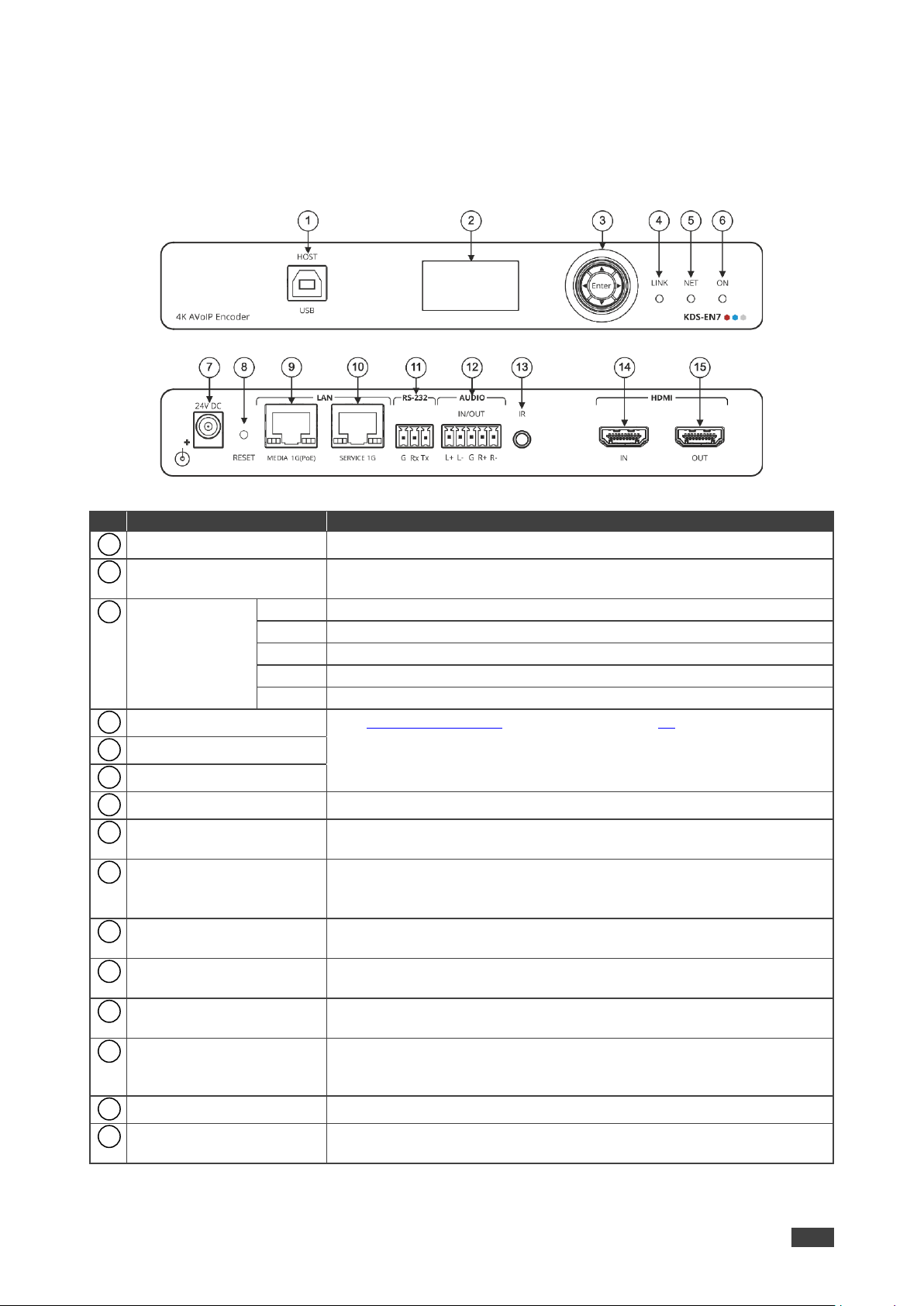
Defining KDS-EN7 4K AVoIP Encoder 7
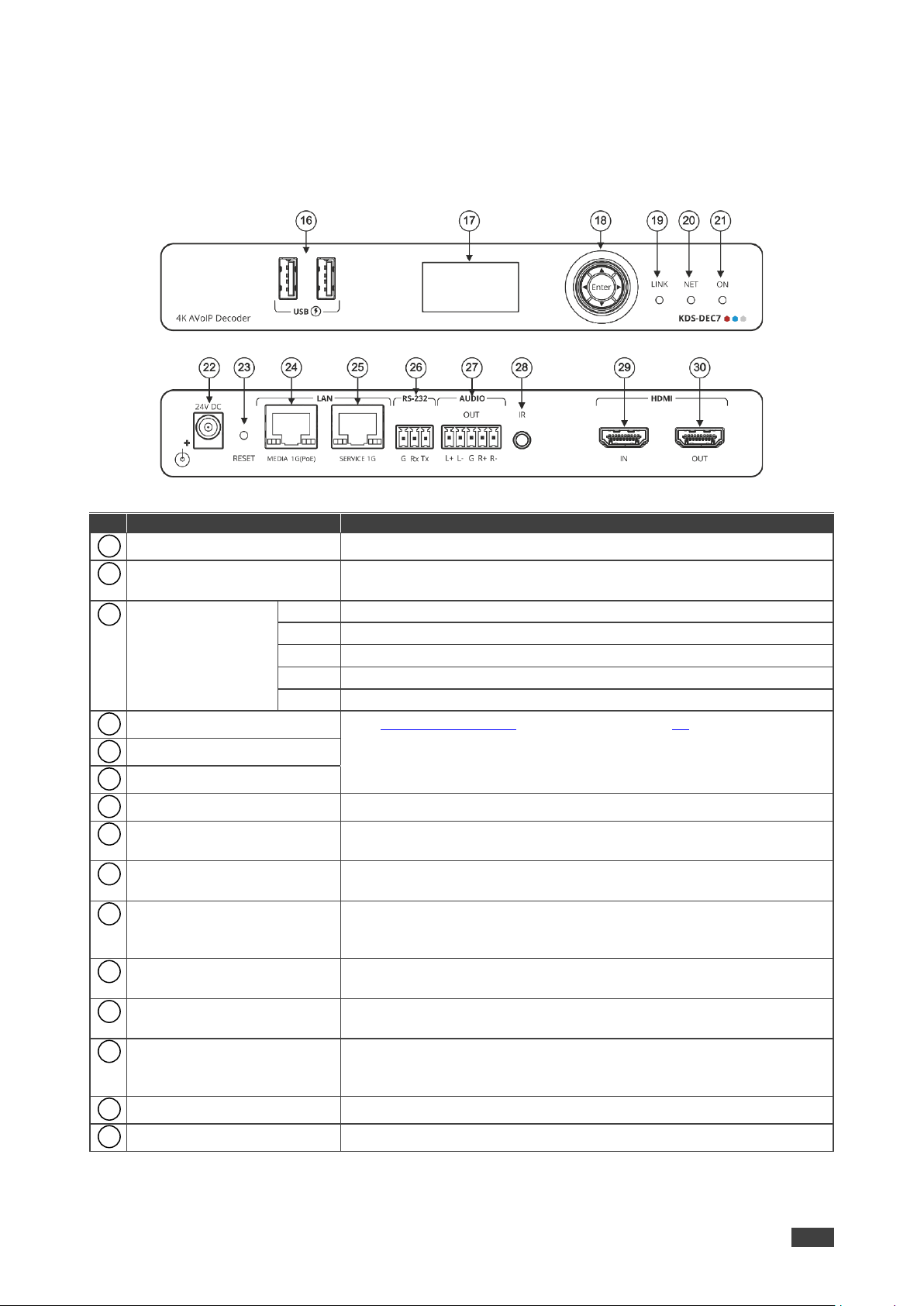
Defining KDS-DEC7 4K AVoIP Decoder 8
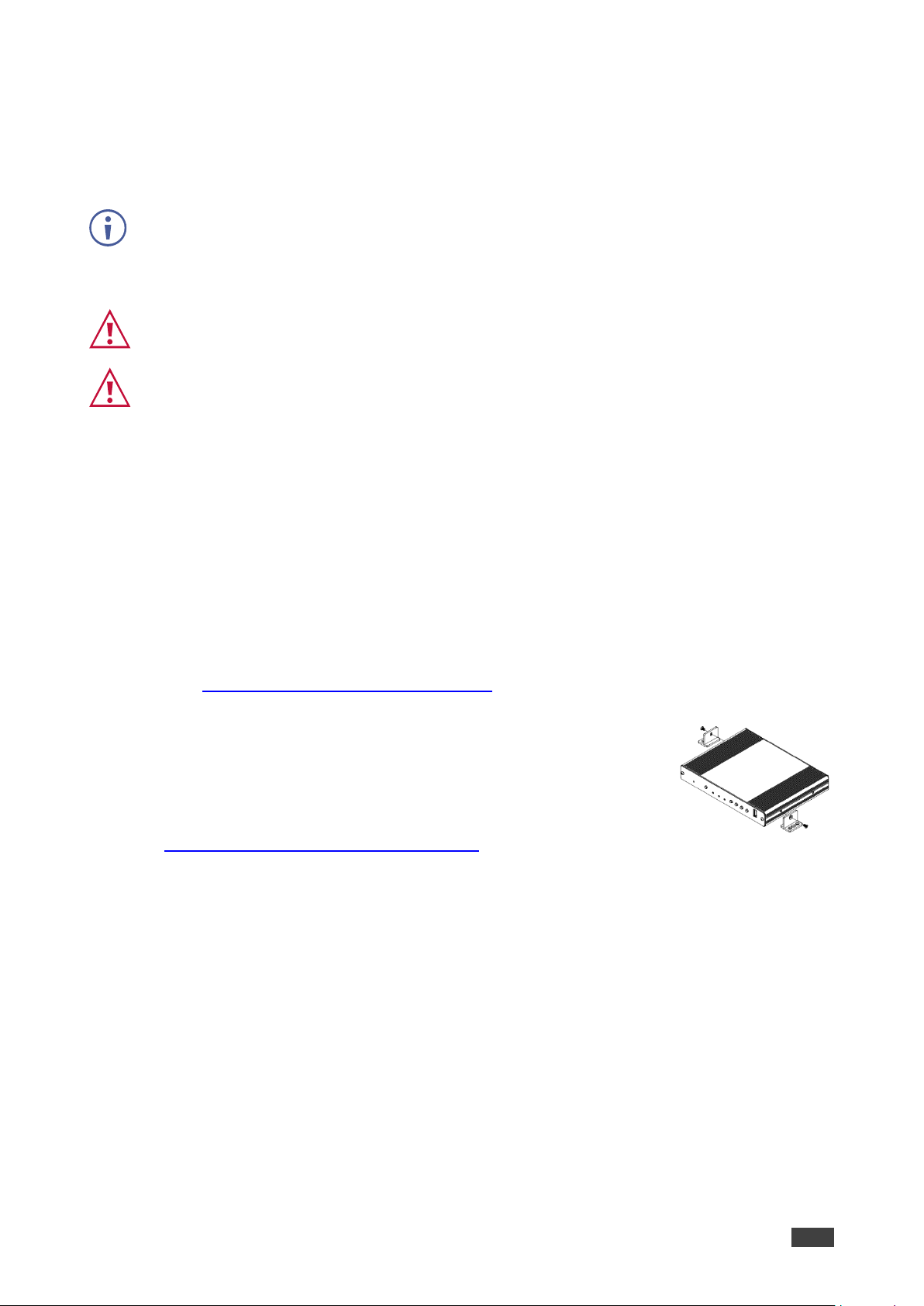
Mounting KDS-EN7 9
Connecting KDS-EN7 10
Connecting the Audio/Input Output 11
Understanding LED Functionality 12
Connecting to KDS-EN7 via RS-232 12
Operating and Controlling KDS-EN7 13
Configuring the Network Switch 13
Using Menu Navigation Buttons 13
Operating via Ethernet 17
Using KDS-EN7 Embedded Web Pages 22
Defining KDS-EN7 AV Routing Parameters 25
Defining HDMI Input Settings 26
Defining Audio Settings 27
Managing EDID 29
General Device Settings 31
KDS-EN7 Network Settings 34
Defining KDS-EN7 Time and Date 36
Setting KDS-EN7 Security 37
Defining KDS-EN7 User Access 41
Defining KDS-EN7 Gateway Settings 44
Viewing KDS-EN7 Status 47
Viewing KDS-EN7 Connections Status 48
Viewing KDS-EN7 Advanced Status 49
Viewing the About Page 50
Using KDS-DEC7 Embedded Web Pages 51
Defining KDS-DEC7 AV Routing Parameters 53
Configuring OSD settings 55
Configuring KVM Settings 57
Setting the Video Wall 59
Configuring the Overlay 62
Defining Video Settings 65
Defining KDS-DEC7 Switching Mode 66
Defining KDS-DEC7 Settings 69
KDS-DEC7 Network Settings 70
Defining KDS-DEC7 Time and Date 71
Setting KDS-DEC7 Security 72
Defining KDS-DEC7 User Access 73
Defining Gateway Settings 73
Viewing KDS-DEC7 Status 74
Viewing KDS-DEC7 Connections Status 75
Viewing KDS-DEC7 Advanced Status 76
Viewing the KDS-DEC7 About Page 77
KVM Roaming, OSD menu and Fast Switching 78
Configuring KVM Roaming 79
KVM and OSD Menu Switching 82
Fast switching configuration 83
Upgrading Firmware 84