Kramer VP-81KSi User manual

Kramer Electronics, Ltd.
USER MANUAL
Model:
VP-81KSi
8x1 UXGA/Audio STEP-IN Switcher

Contents
i
Contents
1Introduction 1
2Getting Started 1
2.1 Quick Start 1
3Overview 3
3.1 Defining EDID 4
4Defining the VP-81KSi 8x1 UXGA/Audio STEP-IN Switcher 5
4.1 Using the IR Transmitter for the VP-81KSi 7
5Installing in a Rack 8
6Connecting the VP-81KSi 8x1 UXGA/Audio STEP-IN Switcher 9
6.1 Connecting the Balanced/Unbalanced Stereo Audio Output 10
6.2 Connecting Remote Contact Closure Input Selection Switches 11
6.3 Connecting the SI-1VGA Remote Step-in Module 11
6.4 Connecting the AV ON CAT 5 Twisted Pair Output 12
6.5 Connecting to the VP-81KSi via the RS-232 Port 12
6.6 Connecting to the VP-81KSi via the RS-485 Port 13
6.6.1 Setting the RS-485 Machine Number and Bus Termination DIP-switches 13
6.6.2 Connecting and Controlling Multiple VP-81KSi Devices 14
6.7 Cascading Multiple VP-81KSi Devices 14
6.8 Connecting to the VP-81KSi via the Ethernet Port 15
6.8.1 Connecting Directly to the Ethernet Port 16
6.8.2 Connecting via a Network Hub, Switch, or Router 17
6.8.3 Configuring the Ethernet Port on the VP-81KSi 17
7Operating the VP-81KSi Locally via the Front Panel Buttons 19
7.1 Using the Front Panel INPUT SELECTOR Buttons 19
7.2 Using the Audio-Follow-Video/Breakaway Modes 19
7.2.1 Operating in Breakaway Mode 20
7.2.2 Switching to Audio Follow Video Mode 20
7.3 Setting the Audio Output Gain 20
7.4 Operating Cascaded VP-81KSi Devices 20
8Operating the VP-81KSi Remotely 21
9Operating the VP-81KSi Remotely using a Web Browser 21
9.1 To Log On to the VP-81KSi Web Pages 22
9.2 The Switching Matrix Page 23
9.2.1 Switching an Input to an Output 24
9.2.2 Operating in the Confirm Mode 25
9.3 The Audio Gain Page 26
9.4 The Configurations Page 27
10 Upgrading the Firmware 28
11 EDID 28

KRAMER: SIMPLE CREATIVE TECHNOLOGY
Contents
ii
12 Technical Specifications 29
13 Communication Parameters 30
14 Default EDID 30
15 Table of ASCII Codes for Serial Communication (Protocol 3000) 31
16 Table of Hex Codes for Serial Communication (Protocol 2000) 32
17 Kramer Protocol 34
17.1 Switching Protocols 34
17.1.1 Switching Protocols via the Front Panel Buttons 34
17.1.2 Switching Protocols via Protocol Commands 34
17.2 Kramer Protocol 3000 34
17.2.1 Protocol 3000 Syntax 35
17.2.2 Command Part Details 35
17.3 Kramer Protocol 2000 42
Figures
Figure 1: VP-81KSi 8x1 UXGA/Audio STEP-IN Switcher Front Panel 5
Figure 2: VP-81KSi 8x1 UXGA/Audio STEP-IN Switcher Rear Panel 6
Figure 3: Connecting the VP-81KSi 9
Figure 4: Balanced Stereo Audio Connection 10
Figure 5: Unbalanced Stereo Audio Connection 10
Figure 6: Remote Input Selection Switch Wiring 11
Figure 7: Connecting the SI-1VGA 12
Figure 8: RS-485 DIP-switches 13
Figure 9: Cascading up to Eight VP-81KSi Devices 15
Figure 10: Local Area Connection Properties Window 16
Figure 11: Internet Protocol (TCP/IP) Properties Window 17
Figure 12: Connect Window 18
Figure 13: Device Properties Window 19
Figure 14: Java Test Page Success Message 21
Figure 15: The Loading Page 22
Figure 16: First Time Security Warning 23
Figure 17: VP-81KSi Switching Matrix Page 24
Figure 18: Switching an Input to an Output25
Figure 19: Switching an Input to an Output 25
Figure 20: Exiting Offline Warning 26
Figure 21: Audio Gain Page 26
Figure 22: Configurations Page 27

Contents
iii
Tables
Table 1: VP-81KSi 8x1 UXGA/Audio STEP-IN Switcher Front Panel Features 5
Table 2: VP-81KSi 8x1 UXGA/Audio STEP-IN Switcher Rear Panel Features 6
Table 3: RS-485 DIP-switch Settings 13
Table 4: Machine Number DIP-switch Settings 14
Table 5: Button Illumination Descriptions 19
Table 6: Technical Specifications of the VP-81KSi 29
Table 7: Communication Parameters 30
Table 8: VP-81KSi Video and Audio Signal Codes 31
Table 9: VP-81KSi Audio Input Gain Codes 32
Table 10: VP-81KSi Audio and Audio Output Gain Codes 32
Table 11: VP-81KSi Hex Codes for Protocol 2000 32
Table 12: VP-81KSi Hex Codes that Increase/Decrease Audio Input Gain 32
Table 13: Hex Codes that Set the Audio Input Gain 33
Table 14: VP-8x8AK Hex Codes for Increasing/Decreasing the Output Gain 33
Table 15: Hex Codes for Setting the Audio Output Gain 33
Table 16: Instruction Codes for Protocol 3000 36
Table 17: Protocol Definitions 42
Table 18: Instruction Codes for Protocol 2000 43

Introduction
1
1 Introduction
Welcome to Kramer Electronics! Since 1981, Kramer Electronics has been
providing a world of unique, creative, and affordable solutions to the vast range of
problems that confront the video, audio, presentation, and broadcasting
professional on a daily basis. In recent years, we have redesigned and upgraded
most of our line, making the best even better! Our 1,000-plus different models now
appear in 11 groups1
Congratulations on purchasing your Kramer VP-81KSi 8x1 UXGA/Audio STEP-IN
Switcher.
that are clearly defined by function.
The VP-81KSi is ideal for:
•Display systems requiring simple input selection
•Remote monitoring of computer activity in schools and businesses
•Rental/staging applications
•Multimedia and presentation source selection
The package includes the following items:
•VP-81KSi 8x1 UXGA/Audio STEP-IN Switcher
•Infrared RC-IR3 remote control transmitter (including the required battery
and a separate user manual2)
•One SI-1VGA Remote Step-in Module and user manual2
•Power cord
•This user manual2
2 Getting Started
We recommend that you:
•Unpack the equipment carefully and save the original box and packaging
materials for possible future shipment
•Review the contents of this user manual
•Use Kramer high performance high resolution cables3
2.1 Quick Start
This quick start chart summarizes the basic setup and operation steps.
1 GROUP 1: Distribution Amplifiers; GROUP 2: Switchers and Matrix Switchers; GROUP 3: Control Systems; GROUP 4:
Format/Standards Converters; GROUP 5: Range Extenders and Repeaters; GROUP 6: Specialty AV Products; GROUP 7: Scan
Converters and Scalers; GROUP 8: Cables and Connectors; GROUP 9: Room Connectivity; GROUP 10: Accessories and Rack
Adapters; GROUP 11: Sierra Products
2 Download up-to-date Kramer user manuals from http://www kramerelectronics com
3 The complete list of Kramer cables is available from http://www kramerelectronics com

KRAMER: SIMPLE CREATIVE TECHNOLOGY
Getting Started
2

Overview
3
3 Overview
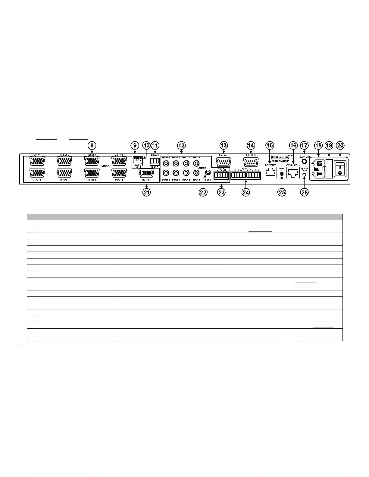
The VP-81KSi routes any input to both outputs, using 15-pin HD female connectors
for the computer graphics video signals, a 3.5mm mini jack for the unbalanced stereo
audio Output 1 signal, and a detachable terminal block connector for the balanced
stereo audio Output 2 signal.
In particular, the VP-81KSi:
•Has a very high video bandwidth ensuring transparent WUXGA performance
•Features audio-follow-video (AFV) in which all operations relate to both the
video and the audio channels, or audio breakaway option, in which video and
audio channels are switched independently
•Features volume control
•Includes the Kramer innovative integrated sync processing Kr-isp™
technology, which lets you achieve a sharp, stable image even when the sync
level is too low, by restoring the sync signal waveform
•Can be cascaded with up to eight units to provide a single “virtual” switcher
with up to 57 inputs
•Supports the SI-1VGA Remote Step-in Panel for remote inputs and remote
step-in control
You can control the VP-81KSi using the front panel buttons, or remotely via:
•RS-485 or RS-232 serial commands transmitted by a touch screen system, PC
or other serial controller
•Ethernet over a LAN using a Web browser
•The SI-1VGA Remote Step-in Panel
•The Kramer RC-IR3 Infrared Remote Control Transmitter or infrared remote
extension cable transmitter (optional)
•Remote, contact closure switches
To achieve the best performance:
•Connect only good quality connection cables, thus avoiding interference,
deterioration in signal quality due to poor matching, and elevated noise levels
(often associated with low quality cables)
•Avoid interference from neighboring electrical appliances that may adversely
influence signal quality and position your VP-81KSi away from moisture,
excessive sunlight and dust

KRAMER: SIMPLE CREATIVE TECHNOLOGY
Overview
4
3.1 Defining EDID
The Extended Display Identification Data (EDID1
) is a data-structure, provided by
a display that describes its capabilities to a graphics card (that is connected to the
display’s source). The EDID enables the PC or laptop to “know” what kind of
monitor is connected to the output. The EDID includes the manufacturer’s name,
product type, timing data supported by the display, display size, luminance data
and (for digital displays only) pixel mapping data.
1 Defined by a standard published by the Video Electronics Standards Association (VESA)

Defining the VP-81KSi 8x1 UXGA/Audio STEP-IN Switcher
5
4 Defining the VP-81KSi 8x1 UXGA/Audio STEP-IN Switcher
Figure 1 and Table 1 define the front panel of the VP-81KSi 8x1 UXGA/Audio STEP-IN Switcher.
Figure 1: VP-81KSi 8x1 UXGA/Audio STEP-IN Switcher Front Panel
Table 1: VP-81KSi 8x1 UXGA/Audio STEP-IN Switcher Front Panel Features
# Feature Function
1 IR Sensor Receiver for the IR Remote Control signal
2 IR LED Lights yellow when the unit receives an IR signal
3 INPUT SELECTOR Buttons Press to select the input (from 1 to 8) to switch to the outputs.
The button lights red if it is selected and here is no input signal.
The buttonlights green if it is not selected but there is an input signal at that input.
The buttonlights violet if it is selected and thereis an input signal connected
4 AUDIO Button Press to execute audio related actions.
The button lights when the audio mode is operational1
5
VIDEO Button Press to execute video related actions.
The button lights when the video mode is operational1
6 AUDIO GAIN Buttons + Press to increase the audio output level of he selected input
2
7
– Press to decrease the audio output level of the selected input2
1 If both the AUDIO and VIDEO buttons are lit, the unit operates in the audio-follow-video mode
2 While the AUDIO button is lit

KRAMER: SIMPLE CREATIVE TECHNOLOGY
Defining the VP-81KSi 8x1 UXGA/Audio STEP-IN Switcher
6
Figure 2 and Table 2 define the rear panel of the VP-81KSi 8x1 UXGA/Audio STEP-IN Switcher.
Figure 2: VP-81KSi 8x1 UXGA/Audio STEP-IN Switcher Rear Panel
Table 2: VP-81KSi 8x1 UXGA/Audio STEP-IN Switcher Rear Panel Features
#
Feature
Function
8 VIDEO INPUT 15-pin HD (F) Connectors Connect to the VGA (up to WUXGA) sources (from 1 to 8)
9 Mach # DIP-switches DIP-switches 1, 2 and 3 for assigning he RS-485 machine number (see Section 6.6.1
10 )
TERM DIP-switch DIP-switch 4 sets RS-485 termination on or off (see Section 6.6.1
11 )
RS-485 Terminal Block Connect to RS-485 port on a remote controller or ano her VP-81KSi (see Section 6.6
12 )
AUDIO INPUT 3 5mm Mini Jacks Connect to the unbalanced stereo audio sources (from 1 to 8)
13 RS-232-1 9-pin D-sub Port (F) Connect to the RS-232 port on a remote controller (see Section 6.3
14 )
RS-232-2 9-pin D-sub Port (M) Connect to an RS-232 controllable device
15 ETHERNET RJ-45 Connector Connect to a remote controller via a LAN (see Section 6.8
16 )
AV ON CAT 5 RJ-45 Connector Connect to a compa ible TP receiver (for example, TP-122)
17 REMOTE IR 3 5mm Mini Jack Connect to an external IR receiver unit for controlling the machine via an IR remote controller (see Section 4.1
18 )
Mains Power Connector Connect to the AC mains supply
19 Main Power Fuse Fuse for protec ing the unit
20 Mains Power Switch AC mains switch
21 OUTPUT 15-pin HD Connector Connect to the VGA (up to WUXGA) acceptor
22 AUDIO OUT 1 3.5mm Mini Jack Connect to the unbalanced stereo audio acceptor
23 AUDIO OUT 2 Terminal Block Connector Connect to the balanced stereo audio acceptor
24 REMOTE Switch Terminal Block Connect to contact closure switches for duplicating the func ion of the front panel Input Selector buttons (see Section 6.2
25 )
PROG. Button For the use of Kramer technical support only
26 FACTORY RESET Button Press and hold while turning the unit on to reset all parameters to factory default values (see Table 7)

Defining the VP-81KSi 8x1 UXGA/Audio STEP-IN Switcher
7
4.1 Using the IR Transmitter for the VP-81KSi
You can use the RC-IR3IR transmitter to operate the machine via the built-in IR
receiver on the front panel or, instead, via an optional external IR receiver1. The
external IR receiver can be located 15m (49ft) away from the machine. This
distance can be extended to up to 60m (197ft) when used with three extension
cables2
Before using the external IR receiver, be sure to arrange for your Kramer dealer to
insert the internal IR connection cable8F
3with the 3.5mm jack that fits into the
REMOTE IR opening on the rear panel. Connect the external IR receiver to the
REMOTE IR 3.5mm jack.
1 Model: C-A35M/IRR-50
2 Model: C-A35M/A35F-50
3 P/N: 505-70434010-S

KRAMER: SIMPLE CREATIVE TECHNOLOGY
Installing in a Rack
8
5 Installing in a Rack
This section describes the preparation and installation of the unit in a rack.

Connecting the VP-81KSi 8x1 UXGA/Audio STEP-IN Switcher
9
6 Connecting the VP-81KSi 8x1 UXGA/Audio STEP-IN Switcher
Figure 3: Connecting the VP-81KSi
To connect1the VP-81KSi, as illustrated in the example in Figure 3:
1. Connect up to eight2SI-1VGA Remote Step-in Panels to the VP-81KSi
15-pin HD VIDEO INPUT connectors3
2. Connect up to eight WUXGA computer graphics sources to the SI-1VGA
15-pin HD video connectors.
and to the 3.5mm mini jacks (from 1
to 8).
3. Connect up to eight unbalanced audio sources to the 3.5mm mini jack audio
connectors on the SI-1VGA panels.
4. Connect the 15-pin HD VIDEO OUTPUT connector to a WUXGA acceptor
(for example, a projector).
1 Be sure that the power is switched off on each device before connecting it to your VP-81KSi After connecting all the devices to your
VP-81KSi, switch on the power of the VP-81KSi, and then switch on the power of each device
2 You do not have to connect all the inputs
3 The cable used must connect all 15 pins

KRAMER: SIMPLE CREATIVE TECHNOLOGY
Connecting the VP-81KSi 8x1 UXGA/Audio STEP-IN Switcher
10
5. Connect the RJ-45 AV ON CAT 5 output connector to a compatible TP
receiver (for example, TP-120).
6. Connect the unbalanced audio 3.5mm AUDIO OUTPUT jack to an
unbalanced audio acceptor (for example, power amplifier).
7. Connect the balanced audio 5-pin terminal block (see Section 6.1) to an audio
acceptor1
8. Connect up to eight remote, contact closure input selection switches to the
REMOTE terminal block (see
.
Section 6.2
9. Connect a PC over a LAN to the Ethernet for remote operation.
).
10. Set the DIP-switches (see Section 6.6.1
RS-232 port (see
) for remote operation. You can
connect a PC and/or controller to the:
Section 6.3
RS-485 port (see )
Section 6.6.1
11. Connect )
1the power cord2
6.1 Connecting the Balanced/Unbalanced Stereo Audio Output
.
This section illustrates how to wire the devices to the balanced audio output:
•A balanced stereo output connection, see Figure 4
•An unbalanced stereo output connection, see Figure 5
Figure 4: Balanced Stereo Audio Connection
Figure 5: Unbalanced Stereo Audio Connection
1 Not shown in the illustration
2 We recommend that you use only the power cord that is supplied with this machine

Connecting the VP-81KSi 8x1 UXGA/Audio STEP-IN Switcher
11
6.2 Connecting Remote Contact Closure Input Selection Switches
You can connect remote input selection switches to the Remote terminal block on
the rear panel of the VP-81KSi which enables you to remotely activate the relevant
input.
The following example (see Figure 6) illustrates three switches (A, B and C)
connected to remotely controlled inputs 1, 2 and 3 respectively (up to eight
switches can be connected). Pressing switch A causes input 1 on the VP-81KSi to
be the active input, pressing switch B causes input 2 to be the active input, and
pressing switch C causes input 3 to be the active input.
Figure 6: Remote Input Selection Switch Wiring
To connect remote input selection switches as illustrated in the example in
Figure 6:
1. Connect Switch A to pins 1 and G1
2. Connect Switch B to pins 2 and G on the terminal block.
1on the terminal block.
3. Connect Switch C to pins 3 and G1on the terminal block.
4. If required, repeat for a total of up to eight switches.
6.3 Connecting the SI-1VGA Remote Step-in Module
For detailed instructions refer to the SI-1VGA Step-in Module Installation
Instructions2
To connect an SI-1VGA remote step-in module to the VP-81KSi as illustrated
in the example in
.
Figure 7:
1. Mount the SI-1VGA in either the TBUS-10 or the K-POD301.
1 You can connect any of the switches to either of the two Gnd connections
2 Available for download from http://www kramerelectronics com

KRAMER: SIMPLE CREATIVE TECHNOLOGY
Connecting the VP-81KSi 8x1 UXGA/Audio STEP-IN Switcher
12
2. Using a 15-pin HD (male to male) cable1
3. Using an audio cable with 3.5mm mini jacks at both ends
, connect the 15-pin HD connector
on the rear of the SI-1VGA to the corresponding input on the rear of the
VP-81KSi. 2
4. Repeat steps 2 and 3 for each SI-1VGA remote step-in module.
, connect the
3.5mm mini connector on the rear of the SI-1VGA to the corresponding audio
input on the rear of the VP-81KSi.
Figure 7: Connecting the SI-1VGA
6.4 Connecting the AV ON CAT 5 Twisted Pair Output
You can connect the VP-81KSi to any compatible Kramer TP (Twisted Pair)
receiver, for example, TP-120 (no audio) or TP-122 (with audio).
For further details, refer to the relevant TP receiver user manual3
6.5 Connecting to the VP-81KSi via the RS-232 Port
.
You can connect to the VP-81KSi via an RS-232 connection using, for example, a
PC.
To connect to the VP-81KSi via RS-232:
•Connect the RS-232 9-pin D-sub rear panel port on the VP-81KSi unit via a
9-wire straight cable (pin 2 to pin 2, pin 3 to pin 3, pin 5 to pin 5) to the
RS-232 9-pin D-sub port on your PC
1 For example, Kramer C-GM/GM
2 For example, Kramer C-A35M/A35M
3 Available for download from http://www kramerelectronics com

Connecting the VP-81KSi 8x1 UXGA/Audio STEP-IN Switcher
13
6.6 Connecting to the VP-81KSi via the RS-485 Port
You can operate the VP-81KSi via the RS-485 port from a distance of up to
1200m (3900ft) using any device equipped with an RS-485 port (for example, a
PC). For successful communication, you must set the RS-485 machine number and
bus termination.
To connect a device with a RS-485 port to the VP-81KSi:
•Connect the A (+) pin on the RS-485 port of the PC to the A (+) pin on the
RS-485 port on the rear panel of the VP-81KSi
•Connect the B (–) pin on the RS-485 port of the PC to the B (–) pin on the
RS-485 port on the rear panel of the VP-81KSi
•Connect the G pin on the RS-485 port of the PC to the G pin on the RS-485
port on the rear panel of the VP-81KSi
6.6.1 Setting the RS-485 Machine Number and Bus Termination DIP-switches
This section describes the VP-81KSi DIP-switch settings that determine the
RS-485 machine number and bus termination.
Figure 8 illustrates the factory default DIP-switch positions.
Figure 8: RS-485 DIP-switches
Table 3: RS-485 DIP-switch Settings
DIP-switch Number Function
1, 2, 3 Machine number (see Table 4)
Default—All off (up), machine number 1
4 RS-485 Bus Termina ion
Default—Off (up)
DIP-switches 1, 2 and 3 determine the RS-485 machine number of the
VP-81KSi. When several VP-81KSi units are connected, the machine number
determines the unique identity of the VP-81KSi on the bus (see Table 4).
Note:
•When using a stand-alone VP-81KSi unit, set the machine number to 1
(factory default)
•When connecting more than one VP-81KSi, set the first machine (connected
via RS-232) to be machine number 1. The other VP-81KSi units must each be
set to a unique machine number between 2 and 16

KRAMER: SIMPLE CREATIVE TECHNOLOGY
Connecting the VP-81KSi 8x1 UXGA/Audio STEP-IN Switcher
14
Table 4: Machine Number DIP-switch Settings
Machine Number 1 2 3
1 (Default) OFF OFF OFF
2 OFF OFF ON
3 OFF ON OFF
4 OFF ON ON
5 ON OFF OFF
6 ON OFF ON
7 ON ON OFF
8 ON ON ON
DIP-switch 4 sets the RS-485 bus termination of the VP-81KSi. Only the first and
last physical units on the RS-485 bus must be terminated, all others must be
unterminated. Moving the DIP-switch up turns the termination off (default),
moving the switch down turns the termination on.
6.6.2 Connecting and Controlling Multiple VP-81KSi Devices
You can daisy-chain up to eight VP-81KSi devices with operation via RS-232
from a PC or serial controller.
To daisy-chain up to eight VP-81KSi devices:
1. Connect the RS-232 port1on the first VP-81KSi device to the PC (see
Section 6.3
2. Connect the RS-485 terminal block port on the first device to the RS-485 port
on the second device, and so on for all devices.
).
3. Set the DIP-switches (see Section 6.6.1
The first device is machine number 1 and the following seven devices
are machine numbers 2 to 8
) as follows:
Terminate the first and last physical devices, that is, in this example
terminate machine numbers 1 and 8. Ensure that all other devices are
unterminated
6.7 Cascading Multiple VP-81KSi Devices
You can cascade up to eight VP-81KSi devices to build a single “virtual” switcher
with up to 57 inputs and one output as illustrated in Figure 9.
To cascade up to eight VP-81KSi devices:
1. Connect the output on the Master VP-81KSi to the video acceptor (for
example, a projector).
2. Connect Input 1 on the Master VP-81KSi to the output of the second device.
3. Connect Input 1 on the second VP-81KSi to the output of the third device,
and so on for all devices.
1 Alternatively, the RS-485 port could be used for PC control

Connecting the VP-81KSi 8x1 UXGA/Audio STEP-IN Switcher
15
Note: Audio connections must follow the same connection scheme as the video
connections.
4. Set the DIP-switches (see Section 6.6.1
The first device is machine number 1 (Master) and the following seven
devices are machine numbers 2 to 8
) as follows:
Terminate the first and last physical devices, that is, terminate machine
numbers 1 and 8. Ensure that all other devices are unterminated
Figure 9: Cascading up to Eight VP-81KSi Devices
Note: The video acceptor must be connected to the Master output. The outputs of
all other devices may be connected to any input on the subsequent device.
For operation of cascaded VP-81KSi devices, see Section 7.4
6.8 Connecting to the VP-81KSi via the Ethernet Port
.
You can connect the VP-81KSi via the Ethernet in the following ways:
•For direct connection to the PC, use a crossover cable (see Section 6.8.1
•For connection via a network hub or network router, use a straight through
cable (see
)
Section 6.8.2
Note: The following instructions are valid only if your PC uses a fixed IP address.
If your PC receives an IP address from a DHCP server, consult your IT department
regarding a suitable IP address.
)

KRAMER: SIMPLE CREATIVE TECHNOLOGY
Connecting the VP-81KSi 8x1 UXGA/Audio STEP-IN Switcher
16
6.8.1 Connecting Directly to the Ethernet Port
You can connect the Ethernet port of the VP-81KSi to the Ethernet port on your
PC via a crossover cable with RJ-45 connectors.
This type of connection is recommended for identification of the factory
default IP address of the VP-81KSi during the initial configuration
To connect the VP-81KSi directly to a PC:
1. Using a crossover cable, connect the VP-81KSi to the PC via the Ethernet
port on both units.
2. On the PC, click Start > Control Panel.
3. Double-click Network Connections.
4. Right-click, and from the menu select Properties.
The Local Area Connection Properties window appears.
Figure 10: Local Area Connection Properties Window
5. Select Internet Protocol (TCP/IP) (see Figure 10).
6. Click the Properties button.
7. Select Use the following IP address, and fill in the details as shown in
Figure 11.
Other manuals for VP-81KSi
1
Table of contents
Other Kramer Switch manuals

Kramer
Kramer VP-796A User manual

Kramer
Kramer VP-770 User manual

Kramer
Kramer VP-553xl User manual

Kramer
Kramer VS-21B User manual

Kramer
Kramer ASPEN-1616UX User manual

Kramer
Kramer Wall Plate Series User manual

Kramer
Kramer VS-801USB User manual

Kramer
Kramer VS-121HC User manual

Kramer
Kramer VP-61N User manual

Kramer
Kramer VP-732 User manual

Kramer
Kramer VS-21HDMI User manual

Kramer
Kramer VM-42 User manual

Kramer
Kramer VS-411UHD User manual

Kramer
Kramer VP-733 User manual

Kramer
Kramer VM-22H User manual

Kramer
Kramer VS-41HDCP User manual

Kramer
Kramer VP-23 User manual

Kramer
Kramer KIT-401 User manual

Kramer
Kramer VS-33Vxl User manual

Kramer
Kramer DIP-31M User manual