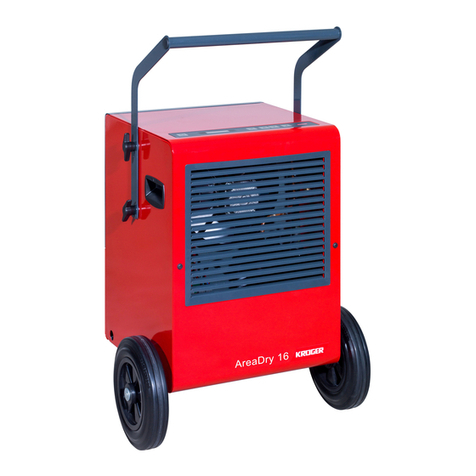
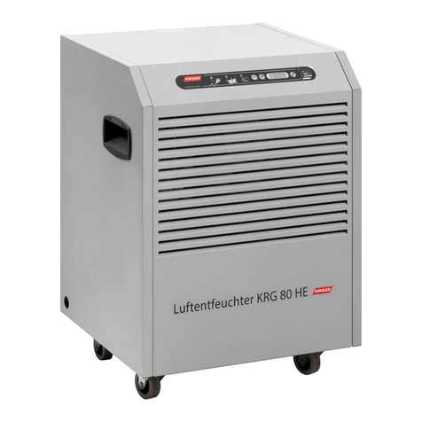
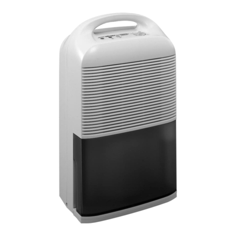
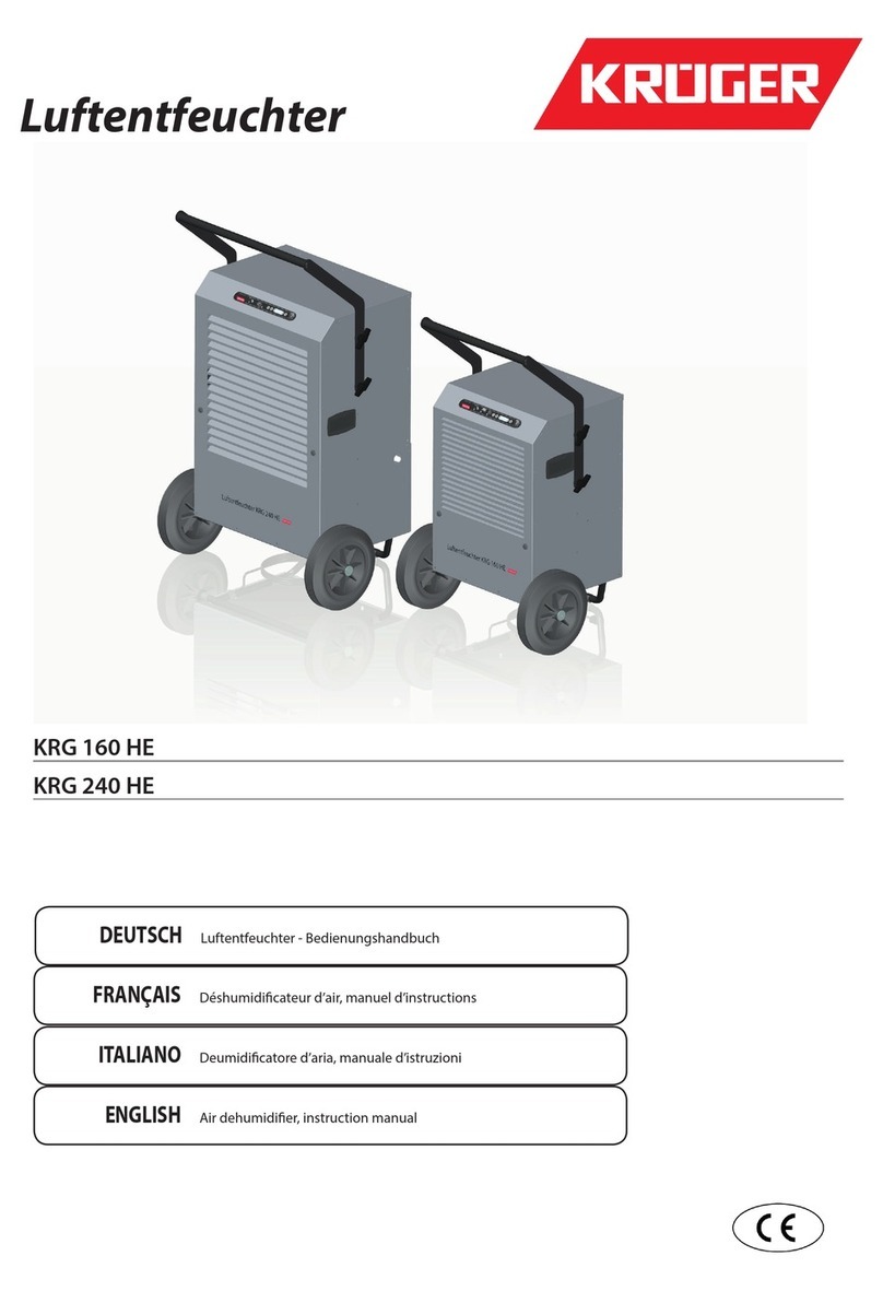
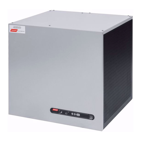
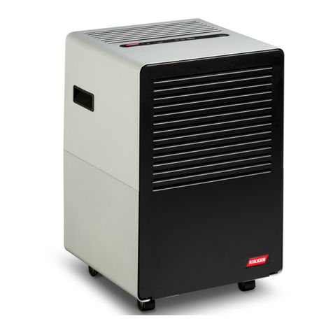
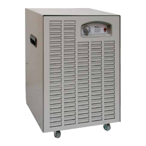
Kruger WMD 80 User manual

ITALIANO
Deumidicatore d’aria, manuale d’istruzioni
Deumidicatore d‘aria
WMD 80
WMD 50
WMD 30
ENGLISH
Air dehumidier, instruction manual
FRANÇAIS
Déshumidicateur d’air, manuel d’instructions
DEUTSCH
Luftentfeuchter - Bedienungshandbuch


ITALIANO 3
M1252-0_draft-2
Legenda simboli
Nota importante: le note servono a evidenziare delle
situazioni e delle condizioni che possono facilitare e
migliorare l’utilizzo dell’apparecchio.
ATTENZIONE: questo avviso segnala una possibile
condizione di pericolo o evidenzia delle situazioni
che, se non gestite nel modo corretto, potrebbero
causare danni alle cose o alle persone. Seguire atten-
tamente quanto scritto.
Avvertenze generali di sicurezza
Conservare e consultare attentamente il presente
manuale in quanto tutte le avvertenze forniscono
indicazioni importanti per la sicurezza nelle fasi di
installazione, uso e manutenzione.
• Questo umidicatore NON è stato progettato per essere uti-
lizzato da persone, compresi bambini, con capacità siche,
sensoriali o mentali ridotte o che mancano di esperienza e
conoscenza sucienti, a meno che non siano stati istruiti
sull’utilizzo corretto dell’apparecchiatura da una persona re-
sponsabile per la loro incolumità. Tenere fuori dalla portata
di bambini e animali.
• Non utilizzare questo apparecchio in luoghi dove ci sia il pe-
ricolo di esplosioni.
• Non utilizzare questo apparecchio in aree la cui aria possa
contenere oli, solfuri o cloro.
• Tenere sempre libere le griglie di ingresso e di uscita dell’aria.
• Non inserire alcun oggetto estraneo all’interno dell’apparec-
chio.
• Assicurarsi che la tensione di alimentazione corrisponda a
quella indicata nella Tab.A, che l’impianto elettrico sia con-
forme alle normative vigenti e adeguatamente protetto.
• L’installazione e la manutenzione dell’apparecchio devono
essere fatte da personale esperto, qualicato e in grado di
svolgere il lavoro secondo le istruzioni riportate in questo
manuale
ATTENZIONE: qualsiasi operazione di manuten-
zione sul circuito frigorifero o sul circuito elettrico
dev’essere eettuata solo da personale esperto e
qualicato.
Uso corretto
Gli apparecchi della serie WMD sono dei deumidicatori d’aria
il cui scopo è di togliere l’umidità dall’ambiente utilizzando
un circuito frigorifero: il nuovo controllo elettronico gestisce
tutte le funzioni del deumidicatore, compreso l’avvio e l’arre-
sto automatico nonché il sistema di sbrinamento se necessario.
Questi apparecchi sono stati concepiti per un uso domestico e
non industriale.
Uso scorretto ragionevolmente
prevedibile
Non utilizzare questo apparecchio in modo diverso
da quello descritto in questo manuale: qualsiasi
altro uso è da ritenersi potenzialmente pericoloso sia
per la macchina che per le persone.
Componenti principali
La staa per l’installazione a muro
Il deumidicatore, per poter funzionare correttamente dev’esse-
re installato a parete mediante l’apposita staa fornita di serie.
Il pannello di comando
Il deumidicatore ha un pannello di comando, sulla parte fron-
tale, che permette di impostare il modo di funzionamento più
idoneo alle proprie esigenze. Una volta impostato, il funziona-
mento è completamente automatico.
Il ltro dell’aria
Il ltro dell’aria si trova sul lato destro del deumidicatore e può
essere facilmente smontato per la pulizia.
Non far funzionare il deumidicatore senza il ltro
dell’aria per evitare che si accumuli dello sporco
sullo scambiatore.
WMD 30 WMD 50 WMD 80
Tensione di alimentazione 230V, 50Hz 230V, 50Hz 230V, 50Hz
Corrente assorbita 1,5 (A) 3,3 (A) 5,2 (A)
Protezione 10 A/T
Potenza assorbita 310 W 720W 1140W
Grado di protezione IP 20
Dimensioni L×A×P 560×323×416 mm 560×400×416 mm 560×504×518 mm
Peso a secco 20,2 kg 28,2 kg 41,8 kg
Temperature di lavoro +10°C / +30°C +10°C / +30°C +10°C / +30°C
Portata d’aria 250 m³/h 600 m³/ora 900 m³/ora
Refrigerante, senza CFC 220g (R134a) 500g (R410a) 950g (R407c)
Volume indicativo trattabile 300 m³ 850 m³ 1200 m³
Capacità serbatoio raccolta condensa ---
Capacità di condensazione 20°C / 60%u.R. 6,3 l/24 19,8 l/24ore 29 l/24ore
Rumorosità a un metro 54 dBa 56 dBa 55 dBa
Tab.A – Dati principali
ITALIANO
4
M1252-0_draft-2
Lo scarico della condensa
L’attacco del tubo dello scarico della condensa si trova sul lato
inferiore destro del deumidicatore.
Non far funzionare il deumidicatore senza aver
prima installato il tubo di scarico della condensa.
Questo deumidicatore NON è dotato di serbatoio
per cui l’acqua viene scaricata direttamente.
Principio di funzionamento
Fig.1 – Schema dei componenti principali
L’aria (14), da deumidicare, viene aspirata dall’apparecchio,
tramite il ventilatore (5), e fatta passare attraverso l’evaporato-
re (9) del circuito frigorifero. In questo modo la temperatura
dell’aria viene abbassata oltre il suo punto di rugiada e il vapore
acqueo condensa in gocce d’acqua che vengono raccolte nell’ap-
posito serbatoio (11).
L’acqua di condensa NON è potabile. Non bere in
nessun caso quest’acqua.
L’aria così deumidicata viene fatta passare attraverso il con-
densatore (10) che ne innalza la temperatura ad un valore leg-
germente superiore rispetto a quello iniziale. In questo modo la
quantità di umidità contenuta nell’aria ambiente viene gradual-
mente diminuita no al valore desiderato.
Quando si deumidica un locale si ottiene anche
un abbassamento dell’umidità nelle pareti e nel
pavimento della camera, nonché nei materiali in
essa contenuti.
Il ciclo di sbrinamento
Se la temperatura scende sotto ai 16 °C circa si può formare
del ghiaccio sull’evaporatore (9). Il ghiaccio dev’essere elimina-
to regolarmente per evitare che impedisca il passaggio dell’aria.
La scheda elettronica gestisce il ciclo di sbrinamento in modo
completamente automatico (vedi più avanti). Durante il ciclo di
sbrinamento il ventilatore (5) viene fermato. La durata del ciclo
dipende dalle condizioni di umidità e temperatura.
Installazione
Per una corretta installazione seguire la sequenza di operazioni
di seguito descritta.
Trasporto e movimentazione
Prima dell’installazione si consiglia di portare la macchina im-
ballata il più possibile vicino al luogo in cui verrà montata.
ATTENZIONE: Le dimensioni e i pesi della macchi-
na richiedono l’ausilio di mezzi quali transpallet e
carrelli per la movimentazione. NON sollevare mai
la macchina da soli.
Posizionamento
Fig.2 – Posizionamento e distanze minime
Installazione a parete
• Utilizzare la staa in dotazione come maschera per segnare i
fori sul muro come mostrato in Fig.3.
Assicurarsi che il muro sia in grado di sostenere
l’apparecchio in condizioni operative.
• Eseguire sul muro n.3 fori Ø10mm profondi 65mm come
indicato in Fig.3. In alternativa, si possono applicare viti più
piccole (non fornite) utilizzando i quattro fori Ø5.
• Pulire l’interno dei fori.
• Inserire i tre tasselli in dotazione tenendo le alette di espan-
sione sul piano verticale.
• Fissare la staa utilizzando le tre viti in dotazione.
Per rispettare la distanza minima di 0,5 metri di
Fig.2 bisogna fare i fori ad almeno 0,8 metri da
terra.
Fig.3 – Fori e posizionamento staffa a muro
• Sollevare la macchina e agganciare la staa posteriore S alla
staa M montata sul muro.

ITALIANO 5
M1252-0_draft-2
Fig.4 – Posizionamento del deumidificatore sul muro
• Ruotare i due piedini T, che si trovano sul lato posteriore, in
basso, del telaio, per rendere uniforme l’appoggio della mac-
china al muro.
• Assicurarsi che il deumidicatore appoggi completamente
sulla staa M posteriore.
Bloccaggio del deumidicatore
Montare la staa di sicurezza R nella parte inferiore del
deumidicatore. La staa dev’essere ssata al muro e alla strut-
tura del deumidicatore mediante le apposite viti.
Fig.5 – La staffa di sicurezza
Non mettere in funzione il deumidicatore senza la
staa di sicurezza. La staa di sicurezza dev’essere
saldamente avvitata al deumidicatore e al muro.
L’assenza della staa di sicurezza può provocare la
caduta accidentale del deumidicatore e causare
danni, anche gravi, a persone e cose.
Il tubo di scarico
Per lo scarico dell’acqua collegare un tubo di gomma diametro
14mm interno all’attacco inferiore D.
Fig.6 – Lo scarico dell’acqua
Per garantire un drenaggio regolare dell’acqua assi-
curarsi che il tubo di scarico sia in pendenza e ben
steso, senza gomiti o strozzature di alcun tipo.
Il pannello di comando
Fig.7 – Il pannello comandi
S1-SpiaverdelineaLaspiasi accendequandoildeumidicatore
funziona, altrimenti lampeggia quando è in stato 0 (alimentato
ma spento).
S3 - Spia gialla sbrinamento La spia si accende quando il
deumidicatore sta eettuando lo sbrinamento automatico.
T1 - Tasto decremento Premendo questo tasto si fa diminuire
il valore indicato nel pannello D no a 0.
T2 - Tasto incremento Premendo questo tasto si fa aumentare
indicato nel pannello D il valore no a C.
D - Display Il display visualizza lo stato di funzionamento del
deumidicatore secondo la tabella riportata di seguito (Tab.B).
Il valore 0 indica lo stato di SPENTO, da 1 a 9 il funzionamento
è automatico ed è comandato dall’umidostato che fa accende-
re o spegnere il deumidicatore a seconda che il valore dell’u-
midità sia superiore o inferiore a quello della Tab.B. Il valo-
re C indica lo stato di FUNZIONAMENTO CONTINUO e il
deumidicatore funziona sempre, indipendentemente dal valo-
re dell’umidità: in ogni caso eventuali allarmi hanno sempre la
priorità sulla modalità di funzionamento impostata.
Display Funzionamento
0O
1 ÷ 2 da 85% circa a 90% U.R.
3 ÷ 4 da 70% circa a 80% U.R.
5 ÷ 6 da 60% circa a 65% U.R.
7 ÷ 8 da 45% circa a 55% U.R.
9circa a 40% U.R.
CContinuo
Tab.B – Tipi di funzionamento
Guasti
Il display, oltre a visualizzare lo stato di funzionamento del
deumidicatore, segnala anche eventuali guasti (Tab.C). Qua-
lora si vericasse una delle condizioni di errore di seguito de-
scritte sarà necessario l’intervento di personale specializzato
per la loro soluzione.
Display Descrizione
nSonda di temperatura rotta o staccata
uSonda umidità rotta o staccata
Tab.C – Segnalazione errori

ITALIANO
6
M1252-0_draft-2
Procedure di utilizzo
Accensione
Quando viene inserita la spina il display D lampeggia per
5 secondi e indica l’ultimo stato di funzionamento del
deumidicatore: poi, se il modo funzionamento è diverso da
zero, il display smette di lampeggiare.
Spegnimento
Per spegnere il deumidicatore premere il tasto T1 no a che il
valore indicato dal display non diventa 0. Quando viene sele-
zionato il modo di funzionamento zero lampeggiano sia la spia
S1 che il display D.
Lo sbrinamento
La scheda elettronica gestisce automaticamente il ciclo di sbri-
namento, che elimina ciclicamente il ghiaccio dallo scambia-
tore, mantenendo eciente il passaggio dell’aria anche alle
temperature più basse. Il ciclo di sbrinamento viene segnalato
dall’accensione della spia S3.
Manutenzione
I deumidicatori della serie WMD non richiedono particolari
cure di manutenzione. E’ consigliabile spolverarli e tenere pu-
lite le grate di entrata e di uscita dell’aria. In caso di malfunzio-
namento o di guasto rivolgersi al proprio rivenditore. In caso
di danneggiamento il cavo deve essere fatto sostituire con uno
analogo da personale esperto e qualicato.
ATTENZIONE: Prima di eseguire qualunque tipo
di intervento sull’apparecchio staccare la spina di
alimentazione della corrente.
Pulizia del ltro
Il ltro può essere pulito con l’aspirapolvere o in acqua: in
quest’ultimo caso attendere che il ltro sia asciutto prima di ri-
montarlo.
Pulire spesso il ltro dell’aria soprattutto nei locali
polverosi: un ltro sporco impedisce il passaggio
dell’aria e riduce l’ecienza del deumidicatore.
Smontaggio del ltro
Rimuovere la griglia anteriore G, quindi smontare il ltro F.
Fig.8 – Il filtro dell’aria.
Montaggio del ltro
Appoggiare il ltro F alla griglia di aspirazione, quindi montare
la griglia anteriore G.
Immagazzinamento
• Conservare l’apparecchio in un ambiente con temperature
comprese tra -25°C e +55°C.
• Quando l’apparecchio è ancora imballato rispettare le indi-
cazioni sulla scatola.
• Non sovrapporre alla scatola altri materiali pesanti.
Veriche da fare prima e dopo
un lungo periodo d’inattività
Prima
• Staccare la spina;
• Coprire la macchina per proteggerla dalla polvere.
Dopo
• La ventola deve girare liberamente senza attriti;
• Attivare l’apparecchio secondo le istruzioni contenute in
questo manuale.
Smaltimento del prodotto
II simbolo del cassonetto barrato indica che il prodotto alla ne
della propria vita utile deve essere raccolto separatamente dagli
altri riuti. L’utente dovrà, pertanto, conferire l’apparecchia-
tura giunta a ne vita agli idonei centri di raccolta dierenziata
dei riuti elettrici ed elettronici, oppure riconsegnarla al riven-
ditore al momento dell’acquisto di un nuovo prodotto di tipo
equivalente, in ragione di uno a uno.
L’adeguata raccolta dierenziata per l’avvio successivo dell’ap-
parecchiatura dimessa al riciclaggio, al trattamento e allo smal-
timento ambientalmente compatibile contribuisce ad evitare
possibili eetti negativi sull’ambiente e sulla salute e favorisce il
riciclo dei materiali di cui e composto il prodotto.

ITALIANO 7
M1252-0_draft-2
Schema elettrico
Fig.9 – Schema elettrico
Rif. Descrizione
1Ventilatore
2Compressore
3Scheda potenza
4Sonda temperatura
6Scheda comando
7Umidostato
8Cavo 10 poli con connettori
9Elettrovalvola
Tab.D – Riferimenti schemi elettrici


ENGLISH 9
M1252-0_draft-2
Symbols
Important note: notes will highlight conditions and
features that can make using the unit easier and bet-
ter.
ATTENTION: this warning indicates a possible dan-
gerous condition or highlights situations that, if not
handled properly, could result in property damage or
personal injury. Carefully follow the description.
General safety rules
Preserve and carefully read this manual as all warn-
ings provide important safety information on instal-
lation, use and maintenance.
• is dehumidier is NOT intended for people, including chil-
dren, with limited physical, sensory or mental capabilities or
without enough experience and knowledge, unless they have
been instructed on its proper use by a person responsible for
their safety. Keep it away from children and animals.
• is dehumidier SHOULD not operate in rooms where a
danger of explosion exists.
• Do NOT use this dehumidier in environments with air con-
taining oil, sulphur or chlorine.
• Always keep the inlet and outlet air grids free.
• Do NOT put any tool inside the unit.
• Make sure that the power supply voltage corresponds to that
indicated in Tab.A, that the electrical installations comply
with the regulations in force and are properly protected.
• Installation and maintenance must be performed by qualied
and experienced sta, able to work according to the instruc-
tions described in this manual.
ATTENTION: any maintenance on the refrigerating
or electric circuit must be carried out only by experi-
enced and qualied sta.
Correct use
e appliances of the WMD series are air dehumidiers that
remove the humidity from the environment using a refriger-
ating circuit: the new electronic control manages all of the de-
humidier’s functions, including automatic start and stop and
defrosting cycle if necessary. ese dehumidiers were designed
for a domestic and not industrial use.
Reasonably foreseeable misuse
Do not use this appliance in ways other than the one
described in this manual: any other use is considered
potentially dangerous both for the machine and for
people.
Main components
The bracket for wall mounting
e dehumidier, in order to function properly it must be in-
stalled on the wall using the bracket supplied as standard.
The control panel
e dehumidier has a control panel, on the front side, which
allows you to set the operating mode that best suits your needs.
Once set, the operation is fully automatic.
The air lter
e air lter is located on the right side of the dehumidier and
can be easily disassembled for cleaning.
Do not run the dehumidier without the air lter to
avoid accumulating dust on the heat exchanger.
The condensate drain
e connection of the condensate drain pipe is located on the
lower right side of the dehumidier.
Do not operate the dehumidier without rst install-
ing the condensate drain pipe. is dehumidier is
NOT equipped with tank and the water is directly
discharged.
WMD 30 WMD 50 WMD 80
Power supply voltage 230V, 50Hz 230V, 50Hz 230V, 50Hz
Current absorption 1,5 (A) 3,3 (A) 5,2 (A)
Protection 10 A/T
Power absorption 310W 720 W 1140W
Protection rating IP 20
Dimensions W×H×D 560×323×416 mm 560×400×416 mm 560×504×518 mm
Dry weight 20,2 kg 28,2 kg 41,8 kg
Working temperature +10°C / +30°C +10°C / +30°C +10°C / +30°C
Air ow 250 m³/h 600 m³/h 900 m³/h
Refrigerant, CFC-free 220g (R134a) 500g (R410a) 950g (R407c)
Indicative handling volume 300 m³ 850 m³ 1200 m³
Condensate collection tank capacity - - -
Condensate capacity at 20°C / 60%r.H. 6,3 l/24 19,8 l/24h 29 l/24h
Noise level at 1 metre distance 54 dBa 56 dBa 55 dBa
Tab.A – Main data

ENGLISH
10
M1252-0_draft-2
Operating principle
Pic.1 – Main components
e appliance uses a fan (5) to suck up the air (14) to be dehu-
midied and pass it through the refrigerator circuit evaporator
(9). In this way the temperature of the air is lowered to below its
dew point and the vapour condenses to form drops of water that
are collected in the appropriate tank (11).
e condensate water is NOT drinkable. Do NOT
drink this water anyway.
e air thus dehumidied is passed through the condenser (10)
that raises its temperature slightly higher than the initial value. In
this way the quantity of humidity contained in the environmen-
tal air is gradually decreased until it reaches the desired value.
When the dehumidier works in a room it reduces
the humidity of the walls and oor of the room, as
well as in the materials contained therein.
The defrosting cycle
If the temperature goes below 16°C ice may form on the evapo-
rator (9). e ice must be regularly melted to prevent it from
reducing the air passage. e electronic board automatically
performs the defrosting cycle (see ahead). During the defrosting
cycle the compressor (6) stops. e time it takes to melt the ice
changes with the humidity and temperature.
Installation
For correct installation, follow the series of operations described
below.
Handling
Before installation it is advisable to bring the packed dehumidi-
er as close as possible to the place where it will be mounted.
CAUTION: e size and the weight of the machine
require the aid of means such as pallet trucks and
trolleys for handling. NEVER li the machine alone.
Placement
Pic.2 – Positioning and minimum distances
Wall installation
• Use the bracket as a template to mark the holes on the wall as
shown in Pic.3.
Make sure that the wall is able to support the device
in operating conditions.
• Drill on the wall n.3 holes Ø10mm, 65mm deep as shown in
Pic.3. Alternatively, you can apply smaller screws (not sup-
plied) using the four Ø5 holes.
• Clean the inside of the holes.
• Insert the three supplied expansion plugs holding in vertical
position the expansion tabs.
• Secure the bracket using the three screws supplied.
To respect the minimum distance of 0,5 meters from
the bottom (Pic.2) drill the holes to at least 0.8 meters
from the oor.
Pic.3 – The wall bracket
• Li the machine and hook the rear bracket S to M bracket
mounted on the wall.
Pic.4 – Placement of the dehumidifier on the wall.

ENGLISH 11
M1252-0_draft-2
• Rotate the two legs T, which are located on the rear-bottom
side of the frame, to make vertical the position of the dehu-
midier.
• Make sure the dehumidier ts completely on the rear brack-
et M.
Safety locking
Install the safety bracket R in the bottom side of the dehumidi-
er. e bracket must be xed to the wall and the structure of the
dehumidier with the screws.
Pic.5 – The safety bracket
Do not operate the dehumidier without the safety
bracket. e safety bracket must be rmly screwed to
the dehumidier and the wall.
e absence of the safety bracket may cause an ac-
cidental fall of the machine and cause damage, even
serious, to persons and property.
The exhaust pipe
For the drain connect a 14mm internal diameter rubber hose to
the connection D on the lower-le side of the frame.
Pic.6 – The water drain
To ensure proper drainage of water make sure that
the drain hose is sloped and well laid out, with no
elbows or narrowing of any kind.
The control panel
Pic.7 – The control panel
S1 - Green light ON e green light indicates when the dehu-
midier is operative, otherwise it blinks on status 0 (powered
but o).
S2 - Red light, full tank e light blinks, together with the green
one S1, when the tank is full, missing or incorrectly positioned.
S3 - Yellow light, defrost e light switches on during the auto-
matic defrosting cycle.
T1 - Decrease button Pushing this button will decrease the val-
ue of the display D down to 0.
T2 - Increase button Pushing this button will increase the value
of the display D up to C.
D - Display e display shows the working state of the dehu-
midier according to the table below (Tab.B). e value 0 means
OFF, from 1 to 9 means automatic functioning and is controlled
by the humidistat that switches the dehumidier on or o if the
value of the relative humidity is higher or lower than the one
shown in Tab.B. e value C means ALWAYS ON and the dehu-
midier works independently from the humidity value: never-
theless, any alarm has priority over the functioning mode.
Display Functioning
0O
1 ÷ 2 from about 85% to 90% R.H.
3 ÷ 4 from about 70% to 80% U.R.
5 ÷ 6 from about 60% to 65% R.H.
7 ÷ 8 from about 45% to 55% R.H.
9about to 40% R.H.
CContinuous
Tab.B – Functioning modes
Failures
e display is used by the electronic device to show particular
situations (Tab.C) If an error message is displayed please contact
your dealer for repair.
Display Description
nTemperature probe must be checked
uHumidity probe must be checked
Tab.C – Error messages

ENGLISH
12
M1252-0_draft-2
How to use
Start-up
When the plug is connected the display D blinks for 5 seconds
and shows the last functioning mode selected: then, if the func-
tioning mode is dierent to zero, the display stops blinking.
Shutdown
To switch o the dehumidier push button T1 until the value
displayed is 0. When zero is selected both the green light S1 and
the display D blink.
The defrosting cycle
e electronic board automatically performs the defrosting cycle
to melt the ice and keep the air ow ecient even at lower tem-
peratures. e yellow light S3 switches on when the defrosting
cycle is started.
Maintenance
e dehumidiers of the WMD series need no particular main-
tenance. It is advisable to dust them and keep the air intake and
outlet grids clean. Contact your dealer if it should function badly
or break down. In the event of damages the cable must be re-
placed with a similar one only by experienced and qualied sta.
ATTENTION: Before doing anything on the appli-
ance disconnect the power supply by unplugging the
machine.
How to clean the lter
e lter can be cleaned with a vacuum cleaner or with water: in
this case dry it before assembly.
Keep the air lter clean, especially in dusty rooms: a
dirty lter reduces the air ow and eciency of the
dehumidier.
How to remove the air lter
Remove the front grid G, then remove the air lter F.
Pic.8 – The air filter.
How to put the air lter on
Place the air lter F on the inlet grid, then mount the front grid
G.
Storage
• Keep the appliance in a room with a temperature between
–25°C and +55°C.
• When the appliance is still packed follow the instructions on
the box.
• Do not place other heavy material on the box.
Checks to carry out before and
after a long period of inactivity
Before
• Disconnect the plug.
• Cover the machine to protect it from dust.
After
• e fan must turn freely without gripping;
• Start the machine following this manual’s instructions.
Disposal of the product
e crossed-out wheelie bin symbol indicates that the product
must be collected separately from other waste at the end of its
useful life.
e user must therefore take the appliance at the end of its useful
life to a special centre for electrical and electronic waste collec-
tion or hand it back to the retailer upon purchase of a new prod-
uct of an equivalent type, on a one-for-one basis.
Proper segregated waste collection of old appliances for subse-
quent recycling, treatment and environmentally compatible dis-
posal helps avoid possible negative eects on the environment
and health and favours recycling of the materials the product is
made of.

ENGLISH 13
M1252-0_draft-2
Wiring diagram
Pic.9 – Wiring diagram
Ref. Description
1Fan
2Compressor
3Electronic power board
4Temperature probe
6Electronic control board
7Humidistat
810 poles cable with plugs
9Solenoid valve
Tab.D – Wiring diagrams references


DEUTSCH 15
M1252-0_draft-2
Symbollegende
Die Hinweise weisen auf Situationen und Bedingun-
gen hin, welche die Verwendung des Gerätes vereinfa-
chen und verbessern können.
ACHTUNG: Dieser Hinweis weist auf eine mögli-
che Gefahr oder Situationen hin, die Personen- und
Sachschäden verursachen können, wenn sie nicht
entsprechend gehandhabt werden. Die Anweisungen
sind exakt zu befolgen.
Allgemeine Sicherheitshinweise
Bitte heben Sie diese Bedienungsanleitung sorgfältig
auf und lesen Sie sie aufmerksam. Sie enthält wichti-
ge Sicherheitshinweise, die bei der Aufstellung, dem
Gebrauch und der Instandhaltung zu berücksichtigen
sind.
• Der Luentfeuchter wurde nicht für eine Bedienung durch
Personen und Kinder konzipiert, die über körperlich, senso-
risch oder geistig eingeschränkte Fähigkeiten verfügen oder
denen eine ausreichende Erfahrung und Kenntnis fehlen, es
sei denn, sie wurden von einer für ihre Unversehrtheit ver-
antwortlichen Person entsprechend bezüglich der Bedienung
des Gerätes angeleitet. Das Gerät ausser der Reichweite von
Kindern und Tieren auewahren.
• Das Gerät nicht in Räumen verwenden, in denen Explosions-
gefahr besteht.
• Das Gerät nicht in Bereichen verwenden, die Ammoniak,
Schwefel- oder Chlorverbindungen enthalten können.
• Keine Fremdkörper in das Gerät einführen.
• Überprüfen, ob die Netzspannung der in Tab.A Angegebenen
entspricht und ob die Elektroanlage die geltenden Normen
erfüllt und angemessen abgesichert ist.
• Das Gerät darf nur von erfahrenem und qualiziertem Per-
sonal installiert und gewartet werden, das in der Lage ist, die
Eingrie unter Beachtung des Handbuch es durchzuführen.
ACHTUNG: Wartungsarbeiten am Kältekreislauf
oder der Elektrik dürfen generell nur von erfahrenem
Fachpersonal ausgeführt werden.
Sachgemässe Verwendung
Alle Geräte der Reihe WMD sind Luentfeuchter, deren Auf-
gabe darin besteht, der Umgebung mithilfe eines Kältekreislau-
fes Feuchtigkeit zu entziehen: Die neue elektronische Steuerung
verwaltet alle Funktionen des Luentfeuchters, inklusive des
automatischen Ein- und Ausschaltens sowie des Abtausystems,
sofern dies erforderlich ist. Die Geräte sind für eine Anwendung
im Haushalt Bereich konzipiert und nicht für den industriellen
Einsatz.
Fehlanwendungen
Das Gerät darf ausschliesslich für die in dieser An-
leitung angegebenen Zwecke verwendet werden: Jede
andere Art der Anwendung ist als potentiell gefähr-
lich für das Gerät und den Menschen zu betrachten.
Bauteile
Bügel für die Wandinstallation
Um einen guten Betrieb gewährleisten zu können, muss der
Luentfeuchter an der Wand unter Verwendung des serienmä-
ssig gelieferten Bügels installiert werden.
Bedienfeld
Der Luentfeuchter ist mit einen bedienfeldausgestattet, das
sich auf der Stirnseite bendet, Damit kann die gewünschte Be-
triebsart eingestellt werden. Nach erfolgter Einstellung funktio-
niert das Gerät vollständig automatisch.
WMD 30 WMD 50 WMD 80
Spannung 230V, 50Hz 230V, 50Hz 230V, 50Hz
Stromaufnahme 1,5 (A) 3,3 (A) 5,2 (A)
Absicherung 10 A/T
Leistungsaufnahme Betrieb 310 W 720W 1140W
Schutzart IP 20
Masse B x H x T 560×323×416 mm 560×400×416 mm 560×504×518 mm
Gewicht 20,2 kg 28,2 kg 41,8 kg
Umgebungstemperatur +10°C / +30°C +10°C / +30°C +10°C / +30°C
Luftdurchsatz 250 m³/h 600 m³/h 900 m³/h
Kältemittel, FCKW-frei 220g (R134a) 500g (R410a) 950g (R407c)
Einsatzbereich bis 300 m³ 850 m³ 1200 m³
Eimerinhalt - - -
Wasserentzug 20°C / 60%r.F. 6,3 l/24 19,8 l/24h 29 l/24h
Geräuschpegel 1 m 54 dBa 56 dBa 55 dBa
Tab.A – Technische Angaben

DEUTSCH
16
M1252-0_draft-2
Luftlter
Der Lulter bendet sich auf der rechten Seite des Gerätes und
kann für die Reinigung leicht demontiert werden.
Den Luentfeuchter nicht ohne Lulter einschalten,
um Schmutzablagerungen am Wärmetauscher zu
vermeiden.
Der Kondenswasserabuss
Der Anschluss des Kondenswasserabuss-Schlauches bendet
sich auf der Unterseite rechts des Luentfeuchters.
Das Gerät darf nicht in Betrieb gesetzt werden ohne
vorher den Kondenswasserabuss-Schlauch ange-
schlossen zu haben. Der Luentfeuchter hat keinen
Auangbehälter, das Wasser iesst direkt ab.
Funktionsprinzip
Abb.1 – Schematische Darstellung der grundlegenden Bauteile
Die zu entfeuchtende Lu (14) wird von dem Gerät mithilfe des
Ventilators (5) eingesaugt und durch den Verdampfer (9) des
Kältekreislaufs geleitet. Auf diese Weise wird die Lu unter ihren
Taupunkt abgekühlt und der Wasserdampf kondensiert zu Was-
sertropfen, die in dem vorgesehenen Behälter (11) aufgefangen
werden.
Das Kondenswasser darf keinesfalls getrunken
werden!
Die so entfeuchtete Lu wird durch den Verüssiger (10) gelei-
tet, der sie auf eine leicht über dem Anfangswert liegende Tem-
peratur aueizt. Auf diese Weise wird die in der Raumlu ent-
haltene Feuchtigkeit schrittweise bis auf den gewünschten Wert
abgesenkt.
Wenn ein Raum entfeuchtet wird, wird gleichzeitig
auch den Wänden und dem Fussboden des Raumes
sowie den Materialien aus denen sie bestehen Feuch-
tigkeit entzogen.
Abtauen
Wenn die Temperatur unter ca. 16 ° C fällt, kann sich Eis am
Verdampfer (9) bilden. Das Eis muss regelmässig entfernt wer-
den, um einen ungehinderten Lustrom zu gewährleisten. Die
Platine steuert den Abtauvorgang vollkommen automatisch
(siehe unten). Während des Abtauvorgangs ist der Verdichter
(6) ausser Betrieb. Die Dauer des Abtauvorgangs hängt von der
Lufeuchtigkeit und der Temperatur ab.
Installation
Für eine korrekte Installation bitten wir folgende Anweisungen
zu beachten.
Transport und Handhabung
Vor der Installation wird empfohlen das Gerät noch verpackt so
nahe wie möglich an den Ort, wo es montiert werden soll, zu
bringen.
ACHTUNG: Auf Grund der Ausmasse und des Ge-
wichts des Gerätes sind Transporthilfsmittel erforder-
lich. Das Gerät NIE alleine heben.
Positionierung
Abb.2 – Positionierung und Mindestabstände
Wandinstallation
• Den in der Ausstattung gelieferten Bügel als Maske für die
Markierung der Bohrungen an der Wand verwenden, wie in
Abb. 3 dargestellt.
Es muss sichergestellt werden, dass die Wand stark ist
das Gerät im Betriebszustand zu halten.
• An der Wand 3 Bohrungen von Ø10mm und 65mm Tiefe,
wie die Abb.3 zeigt, ausführen. Alternativ können kleinere
Schrauben (nicht geliefert), benutzt werden, unter Verwen-
dung den vier Bohrungen von Ø5mm.
• Die Innenwand der Bohrungen reinigen
• Die drei gelieferten Bolzen einstecken und die Dehnungsü-
gel vertikal halten.
• Den Bügel mit den drei gelieferten Schrauben befestigen..
Um einen Mindestabstand von 0,5 m einzuhalten,
siehe Abb. 2, müssen die Bohrungen mit einem Ab-
stand von mindestens 0,8 m vom Boden durchgeführt
werden.
Abb.3 – Bohrungen und Positionierung des Wandbügels

DEUTSCH 17
M1252-0_draft-2
• Die Maschine heben und den hinteren Bügel S an den an der
Wand montierten Bügel M anhaken.
Abb.4 – Positionierung des Entfeuchtungsgerätes an der Wand.
• Die zwei Füsschen T, die sich auf der Hinterseite, am unteren
Rahmen benden, drehen, um ein gleichmässiges Auiegen
des Gerätes an der Wand zu gewährleisten.
• Sicherstellen, dass das Gerät vollständig auf dem hinteren Bü-
gel M auiegt.
Blockierung des Luftentfeuchters
Den Sicherheitsbügel R an der unteren Seite des Gerätes mon-
tieren. Der Bügel muss an die Wand und an die Struktur des
Luentfeuchters mit den dafür bestimmten Schrauben befestigt
werden.
Abb.5 – Der Sicherheitsbügel
Der Luentfeuchter darf keinesfalls ohne den Sicher-
heitsbügel in Betrieb gesetzt werden. Der Sicherheits-
bügel muss fest an der Luentfeuchter und an die
Wand geschraubt werden.
Das Fehlen des Sicherheitsbügels kann einen ver-
sehentlichen Sturz des Gerätes verursachen, was
schwere Schäden an Personen und Sachen zur Folge
haben kann.
Der Abuss-Schlauch
Für den Wasserabuss muss ein Schlauch von 14mm Innen-
durchmesser an den unteren Ansatz D angeschlossen werden.
Abb.6 – Wasserabfluss.
Damit das Wasser korrekt abläu , muss der Ab-
ussschlauch ein Gefälle nach unten haben und
ausgestreckt ohne Schlingen oder Verengungen gleich
welcher Art verlegt werden.
Bedienfeld
Abb.7 – Das Bedienfeld
S1 - Grüne Kontrollleuchte für den Netzstrom Die Kontroll-
leuchte beginnt zu leuchten, wenn der Luentfeuchter in Betrieb
ist, ansonsten blinkt sie, wenn er sich im Zustand 0 bendet (mit
Strom versorgt, jedoch ausgeschaltet).
S3 - Gelbe Kontrollleuchte für Abtauen Die Kontrollleuchte
schaltet sich ein, wenn der Luentfeuchter einen automatischen
Abtauvorgang durchführt.
T1 - Taste zum Verringern Durch Drücken dieser Taste wird
der in der Anzeige D angezeigte Wert bis auf 0 verkleinert.
T2 - Taste zum Erhöhen Durch Drücken dieser Taste wird der
in der Anzeige D angezeigte Wert bis auf C erhöht.
D - Anzeige Die Anzeige zeigt den Betriebszustand des
Luentfeuchters entsprechend der Angaben in der nachstehen-
den Tabelle (Tab.B) an. Der Wert 0 steht für den Zustand AUS-
GESCHALTET, von 1 bis 9 läu das Gerät im Automatikbetrieb
und wird vom Feuchtefühler gesteuert der den Entfeuchter den
Angaben in Tab.B entsprechend ein- und ausschaltet. Der Wert
C steht für den Zuläu stand DAUERBETRIEB, der Luent-
feuchter unabhängig von der Lufeuchte unterbrechungsfrei. In
jedem Fall haben evtl auretende Alarme immer Priorität hin-
sichtlich des eingestellten Betriebsmodus.

DEUTSCH
18
M1252-0_draft-2
Display Betriebsart
0AUS
1 ÷ 2 von 85 % bis ca. 90 % r.F.
3 ÷ 4 von 70 % bis ca. 80 % r.F.
5 ÷ 6 von 60 % bis ca. 65 % r.F.
7 ÷ 8 von 45 % bis ca. 55 % r.F.
9bis ca. 40 % r.F.
CDAUERBETRIEB
Tab.B – Betriebsarten
Defekte
Auf dem Display werden neben dem Funktionsstatus des Lu-
entfeuchter auch eventuelle Defekte (Tab.C) angezeigt. Sollte
einer der beschriebenen Fehler auauchen, ist eine Reparatur
durch Fachpersonal erforderlich.
Display Beschreibung
nTemperatursonde defekt oder abgelöst
uFeuchtigkeitssonde defekt oder abgelöst
Tab.C – Fehlermeldungen
Bedienung
Einschalten
Wenn der Netzstecker eingesteckt wird, blinkt die Anzeige D
5Sekunden lang und zeigt den letzten Betriebszustand des Lu-
entfeuchter an: Die Anzeige hört zu blinken auf, wenn der Be-
triebsmodus von Null verschieden ist.
Ausschalten
Zum Ausschalten des Luentfeuchter die Taste T1 so lange drü-
cken, bis die Anzeige 0 anzeigt. Wenn der Betriebsmodus Null
gewählt wird, blinken sowohl die Kontrollleuchte S1 als auch die
Anzeige D.
Abtauen
Die Platine steuert automatisch den Abtauvorgang. Der Wärme-
tauscher wird vom Eis befreit, wodurch eine eziente Luzirku-
lation auch bei niedrigen Temperaturen gewährleistet wird. Der
Abtauvorgang wird durch das Leuchten der Kontrollleuchte S3
angezeigt.
Instandhaltung
Die Luentfeuchter der Reihe WMD erfordern keine besondere
Pege oder Wartung. Es wird empfohlen, sie abzustauben und
die Gitter am Luein- und Austritt sauber zu halten. Im Falle
von Funktionsstörungen oder einem Defekt wenden Sie sich bit-
te an Ihren Händler. Sollte das Kabel beschädigt sein, muss es
von Fachpersonal durch ein analoges ausgetauscht werden.
ACHTUNG: Bevor an dem Gerät Eingrie jeglicher
Art vorgenommen werden, muss der Netzstecker
gezogen werden.
Reinigung des Filters
Der Filter kann mit einem Staubsauger oder mit Wasser gerei-
nigt werden. Im letzteren Fall mit erneutem Einsetzen warten,
bis der Filter trocken ist.
Den Lulter besonders in staubigen Räumen
häug reinigen: Ein verschmutzter Filter behindert
den Lustrom und reduziert den Wirkungsgrad des
Luentfeuchters.
Ausbau des Filters
Das Frontgitter G entfernen und dann den Filter F demontieren.
Abb.8 – Der Luftfilter.
Filtermontage
Den Filter F auf das Ablugitter legen, dann das Frontgitter G
montieren.
Aufbewahrung
• Das Gerät in einem Raum mit einer Temperatur zwischen
-25°C und +55 °C auewahren.
• Wenn das Gerät noch verpackt sein sollte, bitte die Angaben
auf der Schachtel beachten.
• Keine anderen schweren Materialien auf der Schachtel abstel-
len.
Überprüfungen nach einer län-
geren Nutzungspause
Vorher
• Den Netzstecker ziehen und den Kondenswasserbehälter ent-
leeren.
• Das Gerät abdecken, um es vor Staub zu schützen.
Nachher
• Das Lüerrad muss sich frei und ohne Reibung drehen.
• Das Gerät gemäss Anweisungen einschalten.
Entsorgung des Gerätes
Das Symbol der durchgestrichenen Mülltonne weist darauf hin,
dass das Produkt am Ende seiner Nutzdauer getrennt von ande-
ren Abfällen gesammelt werden muss. Der Benutzer muss des-
halb das Gerät am Ende seiner Nutzdauer einer Sammelstelle für
Elektro- und Elektronikaltgeräte zuführen oder dem Händler
beim Erwerb eines neuen gleichwertigen Gerätes zurückgeben.
Die fachgerechte, getrennte Müllentsorgung ermöglicht ein

DEUTSCH 19
M1252-0_draft-2
Schaltplan
Abb.9 – Schaltplan
Bez. Beschreibung
1Ventilator
2Verdichter
3Leistungsplatine
4Temperaturfühler
6Steuerplatine
7Feuchtigkeitsfühler
810-poliges Kabel mit Steckverbindern
9Magnetventil
Tab.D – Legende der Schaltpläne
sinnvolles Recycling des Altgerätes und eine umweltgerechte
Entsorgung, die dem Schutz unserer Umwelt und Gesundheit
dient, und erleichtert das Recycling der Materialien, aus denen
das Gerät besteht.

This manual suits for next models
2
Table of contents
Languages:
Other Kruger Dehumidifier manuals

Kruger
Kruger KF 675BBC User manual

Kruger
Kruger AIRSEC 3000 User manual

Kruger
Kruger AIRSEC 800 AF User manual

Kruger
Kruger KRK 10 User manual

Kruger
Kruger AreaDry 8 User manual

Kruger
Kruger Airsec 265 AH User manual

Kruger
Kruger KRG 80 HE User manual

Kruger
Kruger KRK 80 User manual

Kruger
Kruger KRP 60 NE User manual

Kruger
Kruger AIRSEC 1400 User manual