KTR Kupplungstechnik
GmbH
D-48407 Rheine
BoWex-ELASTIC®
Operating-/Assembly Instructions
Design 065 (HEW1 and HEW2)
KTR-N
sheet:
edition:
40114 E
7
4
Gezeichnet: 08.04.04 Sha/Hk Ersatz für: KTR-N vom 01.12.99Schutzvermerk
ISO 16016 beachten. Geprüft: 08.04.04 Sha Ersetzt durch:
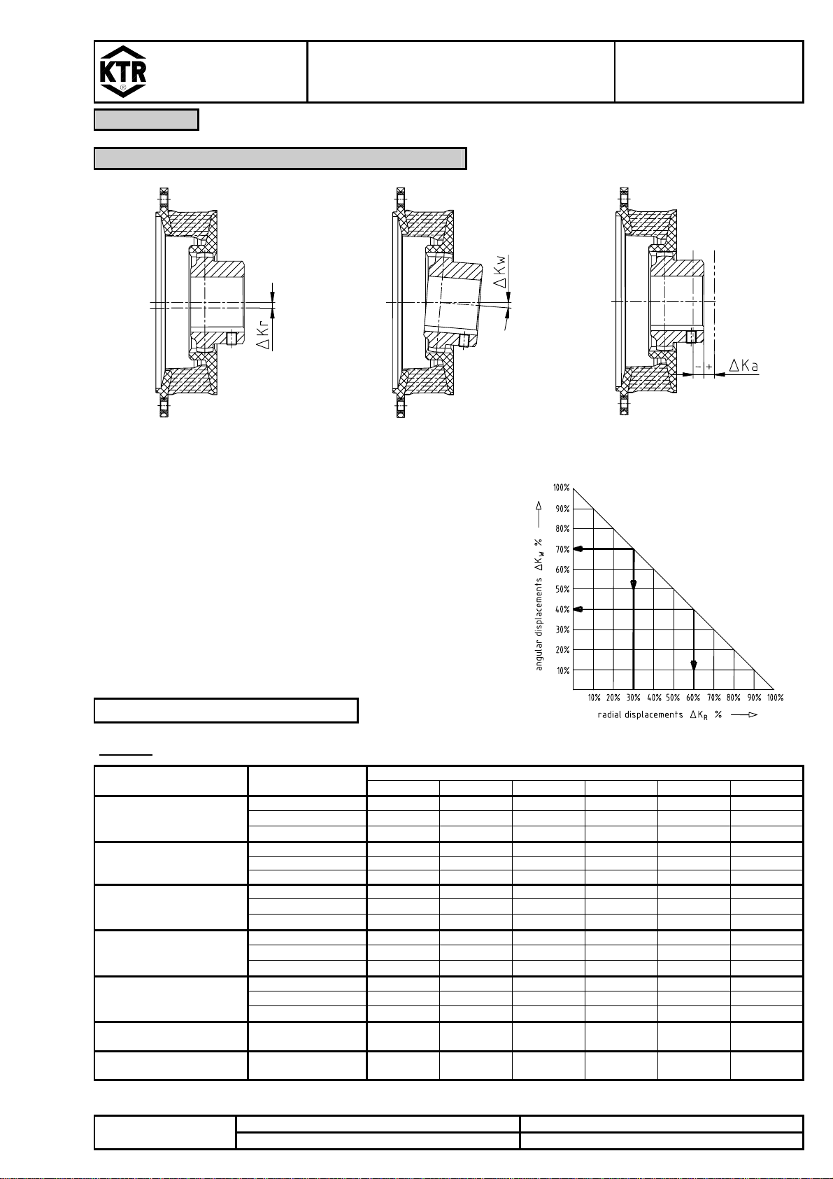
4 Assembly
4.4 Displacements - Alignment of the Couplings
radial displacements angular displacements axial displacements
picture 6: displacements
Example for the misalignment
combinations given in picture 7:
Example 1:
∆KR= 30%
∆KW= 70%
Example 2:
∆KR= 60%
∆KW= 40%
∆Ktotal = ∆KR+ ∆KW≤100 %
picture 7: combinations
of displacement
Table 5:
BoWex-ELASTIC®HEW size
displacements elastomer-hardness
[Shore A] W 42 HE 42 HE 48 HE 65 HE 80 HE G 80 HE
40 1,0 1,1 1,2 1,6 1,8 2,0
50 - 1,0 1,1 1,5 1,7 1,9
perm. radial displacement
with n=1500 1/min.
∆Kr (mm) 65 - 0,5 0,5 0,7 0,8 0,9
40 0,7 0,8 1,1 1,4 1,6 1,8
50 - 0,7 1,0 1,3 1,5 1,7
perm. radial displacement
with n=3000 1/min.
∆Kr (mm) 65 - 0,4 0,4 0,5 0,6 0,8
40 3,2 3,6 3,8 5,1 5,7 6,0
50 - 3,3 3,5 4,7 5,3 5,7
max. radial displacement
∆Krmax. (mm) 1) 65 - 1,5 1,7 2,2 2,4 2,7
40 1,0 1,0 1,0 1,0 1,0 1,0
50 - 0,75 0,75 0,75 0,75 0,75
perm. angular displacement
with n=1500 1/min.
∆Kw (°) 65 - 0,5 0,5 0,5 0,5 0,5
40 0,5 0,5 0,5 0,5 0,5 0,5
50 - 0,4 0,4 0,4 0,4 0,4
perm. angular displacement
with n=3000 1/min.
∆Kw (°) 65 - 0,25 0,25 0,25 0,25 0,25
max. angular displacement
∆Kwmax. (°) 1) 40 / 50 / 65 1,5 1,5 1,5 1,5 1,5 1,5
perm. axial displacement
∆Ka (mm) 40 / 50 / 65 ±2 ±2 ±2 ±2 ±2 ±3
1) for short-term start