KTR GEARex FA Manual

GEARex®
Operating/Assembly instructions
KTR-N
Sheet:
Edition:
40310 EN
1 of 36
15
Please observe protection
note ISO 16016.
Drawn:
2019-09-19 Pz/Wb
Replacing:
KTR-N dated 2017-01-02
Verified:
2019-09-19 Pz
Replaced by:
GEARex®
All-steel gear couplings type:
FA, FB, FAB, DA, DB and DAB along with their combinations
according to directive 2014/34/EU
Type FA
Type FB
Type FAB
Type DA
Type DB
Type DAB
FH, DH, FR and DR along with combinations
for finish bored, pilot bored and unbored couplings
Type FH
Type DH
Type FR
Type DR

GEARex®
Operating/Assembly instructions
KTR-N
Sheet:
Edition:
40310 EN
2 of 36
15
Please observe protection
note ISO 16016.
Drawn:
2019-09-19 Pz/Wb
Replacing:
KTR-N dated 2017-01-02
Verified:
2019-09-19 Pz
Replaced by:
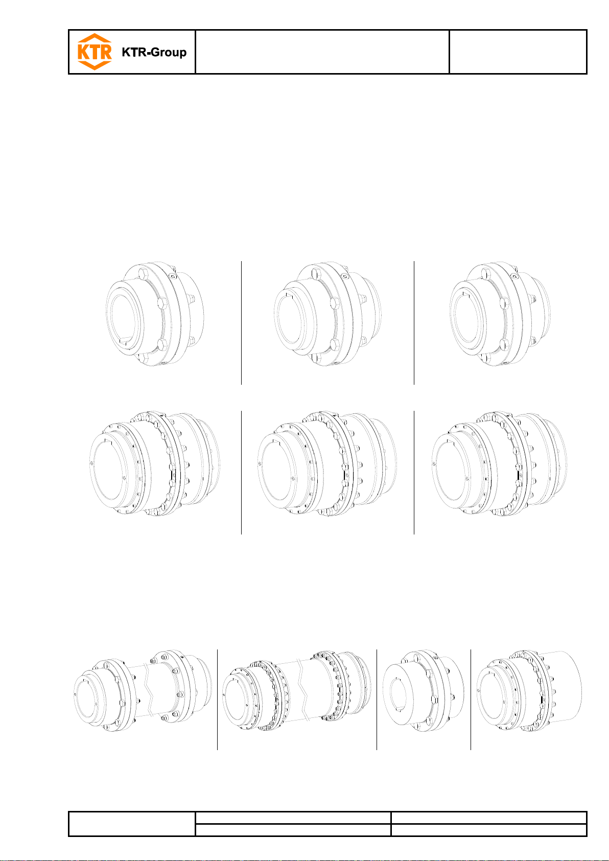
The GEARex®all-steel gear coupling is a flexible shaft connection. It is able to compensate for shaft
misalignment, for example caused by manufacturing inaccuracies, thermal expansion, etc.
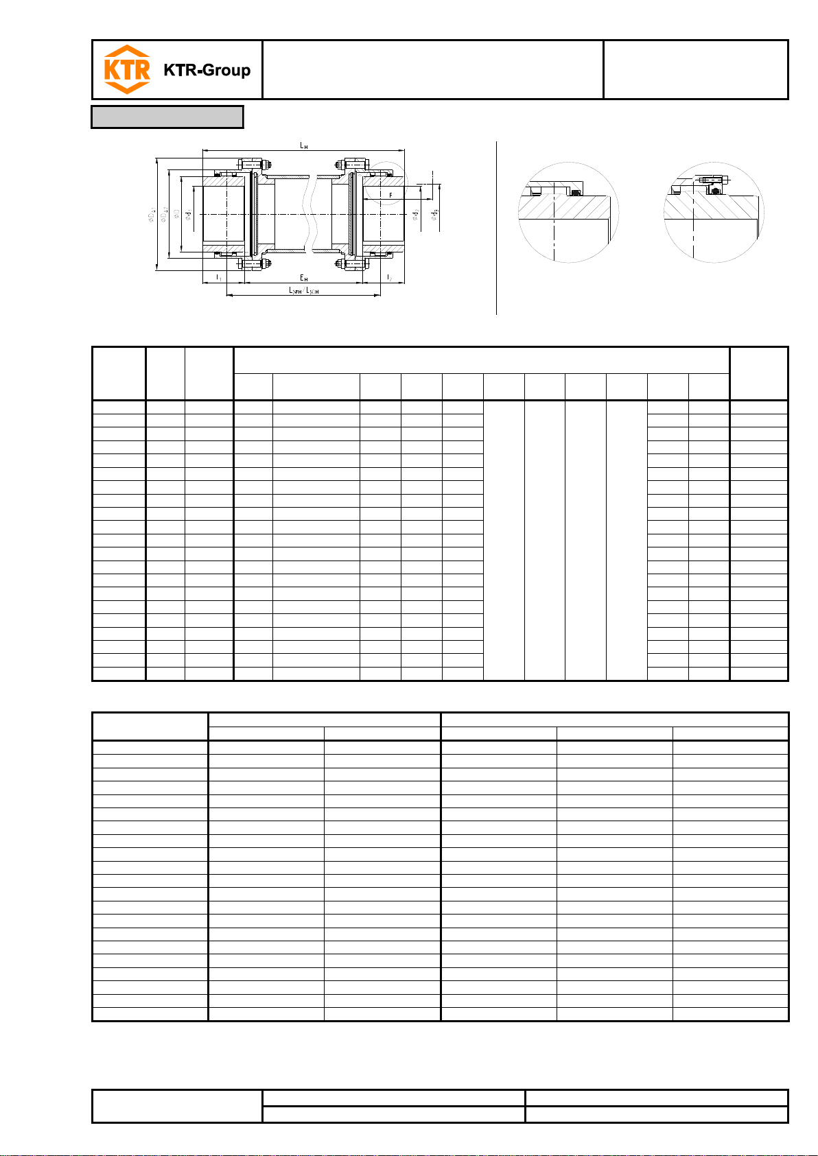
1Technical data 4
2Advice 8
2.1 General advice 8
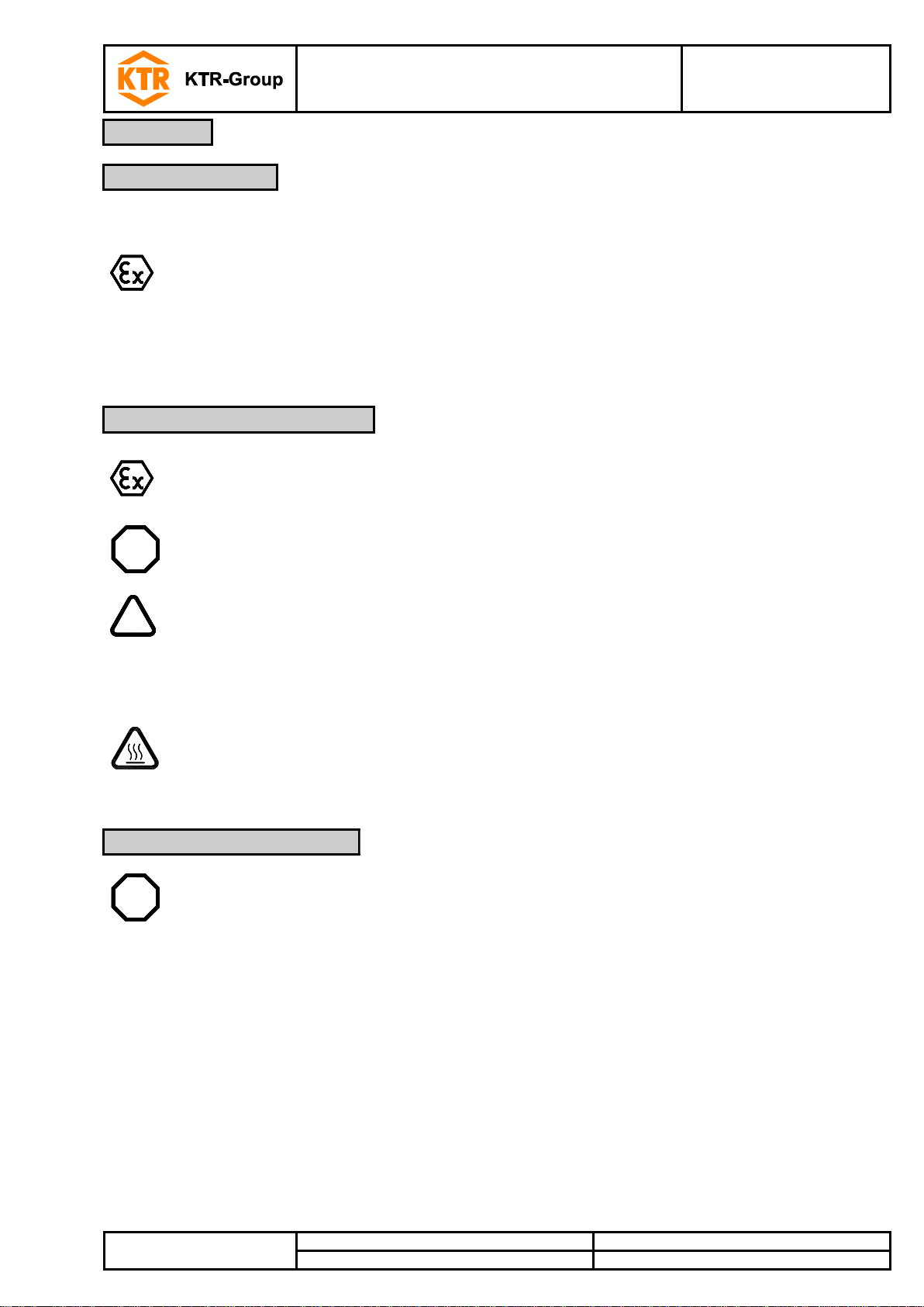
2.2 Safety and advice symbols 8
2.3 General hazard warnings 8
2.4 Intended use 9
2.5 Coupling selection 9
2.6 Reference to EC Machinery Directive 2006/42/EC 9
3Storage, transport and packaging 10
3.1 Storage of the coupling 10
3.2 Storage of O-rings 10
3.3 Transport and packaging 10
4Assembly 10
4.1 Components of the couplings 11
4.2 Advice for finish bore 15
4.3 Assembly of the coupling (general) 16
4.4 Assembly of the types FA, FB, FAB, FH and FR 17
4.5 Assembly of types DA, DB, DAB, DH and DR 18
4.6 Displacements - alignment of the couplings 20
5Start-up and lubrication 21
5.1 Start-up of the coupling 21
5.2 Types of grease recommended 22
5.3 Grease feeding 23
5.4 Grease capacity 23
6Breakdowns, causes and elimination 24
7Maintenance and service 27
7.1 Intervals of maintenance 27
7.2 Replacement of grease 27
7.3 Replacement of sealing elements 28
7.4 Standard values for circumferential backlash 29
7.5 Standard values of wear 30
7.6 Cleaning of the coupling 31
7.7 Replacement of coupling 31
7.8 Disassembly of the coupling 31
8Disposal 32
9Spares inventory, customer service addresses 32
Table of contents

GEARex®
Operating/Assembly instructions
KTR-N
Sheet:
Edition:
40310 EN
3 of 36
15
Please observe protection
note ISO 16016.
Drawn:
2019-09-19 Pz/Wb
Replacing:
KTR-N dated 2017-01-02
Verified:
2019-09-19 Pz
Replaced by:
10 Enclosure A
Advice and instructions regarding the use in potentially explosive atmospheres 33
10.1 Intended use in potentially explosive atmospheres 33
10.2 Inspection intervals for couplings in potentially explosive atmospheres 34
10.3 marking of coupling for potentially explosive atmospheres 35
10.4 EU Certificate of conformity 36
Table of contents

GEARex®
Operating/Assembly instructions
KTR-N
Sheet:
Edition:
40310 EN
4 of 36
15
Please observe protection
note ISO 16016.
Drawn:
2019-09-19 Pz/Wb
Replacing:
KTR-N dated 2017-01-02
Verified:
2019-09-19 Pz
Replaced by:
Illustration 1: Type FA
Illustration 2: Type FB
Illustration 3: Type FAB
Table 1: Dimensions - FA, FB and FAB
Size
Pilot
bore
Max.
finish
bore
d1, d2
Dimensions [mm]
Grease
feeding
2)
[dm3]
l1, l2
l1, l23)
EFA
EFB
EFAB
LFA
LFB
LFAB
L3
D
DA1
DA2
F 1)
d3 1)
10
26
50
43
105
3
21
12
89
107
98
55
67
111
84
74
52
0.02
15
26
64
50
115
3
15
9
103
115
109
59
87
152
107
84
68
0.04
20
31
80
62
130
3
31
17
127
155
141
79
108
178
130
104
85
0.08
25
38
98
76
150
5
29
17
157
181
169
93
130
213
158
123
110
0.12
30
44.5
112
90
170
5
33
19
185
213
199
109
153
240
182
148
130
0.18
35
46
133
105
185
6
40
23
216
250
233
128
180
280
214
172
150
0.22
40
52
158
120
215
6
42
24
246
282
264
144
214
318
250
192
175
0.35
45
80
172
135
245
8
50
29
278
320
299
164
233
347
274
216
190
0.45
50
80
192
150
295
8
56
32
308
356
332
182
260
390
309
241
220
0.70
55
90
210
175
300
8
70
39
358
420
389
214
283
425.5
334
275
250
0.90
60
100
232
190
305
8
84
46
388
464
426
236
312
457
365.5
316
265
1.15
70
100
276
220
310
10
76
43
450
516
483
263
371
527
425
360
300
1.50
Table 2: Technical data - FA, FB and FAB
Size
Torque 4) [Nm]
Max. speed
[rpm]
Weight with max. bore [kg]
Mass moment of
inertia with max.
bore [kgm2]
Dowel screws (10.9)/nuts
TKN
TKN
(42 CrMo4)
Sleeve
Hub
Total
z
M
TA[Nm]
10
930
1580
8500
0.75
0.55
2.73
0.00436
6
M6
15
15
2000
3300
6400
1.88
1.12
6.38
0.01894
8
M8
36
20
3500
6300
5400
2.60
2.09
9.94
0.04000
6
M10
72
25
6500
11000
4500
4.43
3.56
16.83
0.09749
6
M12
125
30
10000
17400
4000
5.83
6.18
25.21
0.18080
8
M12
125
35
17000
28800
3500
9.71
9.87
41.25
0.41419
8
M14
200
40
28500
48500
3100
11.88
16.07
58.14
0.75535
8
M14
200
45
37000
62000
3000
15.72
21.42
77.08
1.17590
10
M14
200
50
51000
86000
2500
25.66
29.59
114.40
2.24991
8
M18
430
55
65000
110000
2300
31.52
40.30
150.41
3.45102
14
M18
430
60
85000
145000
2100
32.82
52.96
177.44
4.16734
14
M18
430
70
135000
240000
1850
43.52
85.77
268.20
9.32429
16
M20
610
1) Space required to align the coupling and replace the gasket
2) Grease feeding for each coupling half
3) Hub lengthened max. l1, l2
4) Maximum torque of the coupling TK max = rated torque of the coupling TK rated x 2
1 Technical data

GEARex®
Operating/Assembly instructions
KTR-N
Sheet:
Edition:
40310 EN
5 of 36
15
Please observe protection
note ISO 16016.
Drawn:
2019-09-19 Pz/Wb
Replacing:
KTR-N dated 2017-01-02
Verified:
2019-09-19 Pz
Replaced by:
Illustration 4: Type DA
Illustration 5: Type DB
Illustration 6: Type DAB
Table 3: Dimensions - DA, DB and DAB
Size
Pilot
bore
Max.
finish
bore
d1, d2
Dimensions [mm]
Grease
feeding
2)
[dm3]
l1, l2
EDA
EDB
EDAB
LDA
LDB
LDAB
L3
D
DA1
DA2
F 1)
d3 1)
20
31
80
62
3
31
17
133
155
144
79
108
187
146
105
85
0.08
25
38
98
76
5
29
17
157
181
169
93
130
220
172
115
105
0.12
30
44.5
112
90
5
33
19
185
213
199
109
153
248
182
140
120
0.18
35
46
133
105
6
40
23
216
250
233
128
180
285
214
165
145
0.22
40
52
158
120
6
42
24
246
282
264
144
214
335
250
180
160
0.35
45
80
172
135
8
50
29
278
320
299
164
233
358
294
195
185
0.45
50
80
192
150
8
56
32
388
356
332
182
260
390
309
215
205
0.70
55
90
210
175
8
70
39
358
420
389
214
283
425.5
348
240
220
0.90
60
100
232
190
8
84
46
388
464
426
236
312
457
380
260
245
1.15
70
100
276
220
10
76
43
450
516
483
263
371
527
445
300
290
1.50
80
140
300
280
10
50
30
570
610
590
310
394
545
475
340
310
2.50
85
160
325
292
13
53
33
597
637
617
325
430
585
515
352
330
3.00
90
180
350
305
13
83
48
623
693
658
353
464
640
560
365
360
4.00
100
220
390
330
13
93
53
673
753
713
383
512
690
612
390
400
5.00
110
220
420
350
20
296
158
720
996
858
508
560
765
665
410
420
6.00
120
260
450
420
25
421
223
864
1261
1063
643
608
825
720
480
470
7.50
130
300
500
440
25
415
220
905
1295
1100
660
684
950
805
520
520
9.00
140
380
550
460
20
430
225
940
1350
1145
685
750
1020
875
570
590
12.00
150
460
630
520
30
460
245
1070
1500
1285
765
850
1140
975
630
670
15.00
Table 4: Technical data - DA, DB and DAB
Size
Torque 3) [Nm]
Max. speed
[rpm]
Weight with max. bore [kg]
Mass moment of
inertia with max.
bore [kgm2]
Dowel screws (10.9)/nuts
TKN
TKN
(42 CrMo4)
Sleeve
Hub
Total
z
M
TA[Nm]
20
3500
6300
5400
3.6
2.1
12.8
0.056
6
M10
72
25
6500
11000
4500
5.5
3.5
20.3
0.125
6
M12
125
30
10000
17400
4000
6.8
6.2
28.9
0.220
8
M12
125
35
17000
28800
3500
11.2
9.8
46.6
0.488
8
M14
200
40
28500
48500
3100
16.3
15.9
70.9
1.011
8
M14
200
45
37000
62000
3000
20.2
21.4
90.7
1.482
10
M14
200
50
51000
86000
2500
27.2
29.5
124
2.474
8
M18
430
55
65000
110000
2300
40
40
175
4.047
14
M18
430
60
85000
145000
2100
32
53
185
4.810
14
M18
430
70
135000
240000
1850
44
85
280
9.907
16
M20
610
80
175000
300000
1750
64
117
362
14.214
18
M20
610
85
225000
380000
1650
75
148
446
20.320
20
M20
610
90
290000
500000
1550
101
183
568
31.036
20
M24
1000
100
380000
650000
1500
117
232
698
45.358
24
M24
1000
110
480000
820000
1250
140
295
940
73.880
20
M30
1700
120
620000
1050000
1150
188
430
1312
118.40
24
M30
1700
130
-
1450000
1000
319
603
1954
226.732
20
M36
2800
140
-
1950000
950
373
758
2391
328.567
24
M36
2800
150
-
2750000
850
475
983
3069
540.298
30
M36
2800
1) Space required to align the coupling and replace the gasket
2) Grease feeding for each coupling half
3) Maximum torque of the coupling TKmax. = rated torque of the coupling TK rated x 2
1 Technical data

GEARex®
Operating/Assembly instructions
KTR-N
Sheet:
Edition:
40310 EN
6 of 36
15
Please observe protection
note ISO 16016.
Drawn:
2019-09-19 Pz/Wb
Replacing:
KTR-N dated 2017-01-02
Verified:
2019-09-19 Pz
Replaced by:
Type FH
(size 10 to 70)
Type DH
(size. 80 to 150)
Illustration 7
Illustration 8: type FH / DH
Table 5: Dimensions - FH and DH
Size
Pilot
bore
Max.
finish
bore
d1, d2
Dimensions [mm]
Grease
feeding 2)
[dm3]
l1, l2
Hub lengthened
max. l1, l2
D
DA1 3)
DA2 3)
LH
L3FH
L3DH
EH
F 1)
d3 1)
10
26
50
43
105
67
111
84
LH= EH+ l1+ l2
According to customer specification
74
52
0.02
15
26
64
50
115
87
152
107
84
68
0.04
20
31
80
62
130
108
178
130
104
85
0.08
25
38
98
76
150
130
213
158
123
110
0.12
30
44.5
112
90
170
153
240
182
148
130
0.18
35
46
133
105
185
180
280
214
172
150
0.22
40
52
158
120
215
214
318
250
192
175
0.35
45
80
172
135
245
233
347
274
216
190
0.45
50
80
192
150
295
260
390
309
241
220
0.70
55
90
210
175
300
283
425.5
334
275
250
0.90
60
100
232
190
305
312
457
365.5
316
265
1.15
70
100
276
220
310
371
527
425
360
300
1.50
80
140
300
280
-
394
545
475
340
310
2.50
85
160
325
292
-
430
585
515
352
330
3.00
90
180
350
305
-
464
640
560
365
360
4.00
100
220
390
330
-
512
690
612
390
400
5.00
110
220
420
350
-
560
765
665
410
420
6.00
120
260
450
420
-
608
825
720
480
470
7.50
130
300
500
440
-
684
950
805
520
520
9.00
140
380
550
460
-
750
1020
875
570
590
12.00
150
460
630
520
-
850
1140
975
630
670
15.00
Table 6: Technical data - FH and DH
Size
Torque 4) [Nm]
Dowel screws (10.9)/nuts
TKN
TKN (42 CrMo4)
z 5)
M
TA[Nm]
10
930
1580
6
M6
15
15
2000
3300
8
M8
36
20
3500
6300
6
M10
72
25
6500
11000
6
M12
125
30
10000
17400
8
M12
125
35
17000
28800
8
M14
200
40
28500
48500
8
M14
200
45
37000
62000
10
M14
200
50
51000
86000
8
M18
430
55
65000
110000
14
M18
430
60
85000
145000
14
M18
430
70
135000
240000
16
M20
610
80
175000
300000
18
M20
610
85
225000
380000
20
M20
610
90
290000
500000
20
M24
1000
100
380000
650000
24
M24
1000
110
480000
820000
20
M30
1700
120
620000
1050000
24
M30
1700
130
-
1450000
20
M36
2800
140
-
1950000
24
M36
2800
150
-
2750000
30
M36
2800
1) Space required to align the coupling and replace the gasket
2) Grease feeding for each coupling half
3) For dimensions of type F see table 1; type D see table 3
4) Maximum torque of the coupling TKmax. = rated torque of the coupling TK rated x 2
5) Number for each coupling half
1 Technical data

GEARex®
Operating/Assembly instructions
KTR-N
Sheet:
Edition:
40310 EN
7 of 36
15
Please observe protection
note ISO 16016.
Drawn:
2019-09-19 Pz/Wb
Replacing:
KTR-N dated 2017-01-02
Verified:
2019-09-19 Pz
Replaced by:
Type FR
(size 10 to 70)
Type DR
(size. 80 to 150)
Illustration 9
Illustration 10: Type FR / DR
Table 7: Dimensions - FR and DR
Size
Max. finish bore
Dimensions [mm]
Grease
feeding 2)
[dm3]
d1
d4
l1, l2
Hub
lengthened
max. l1, l2
D
DA1
DA2
DF
LR
F 1)
d3 1)
10
50
60
43
105
67
111
84
84
88
74
52
0.02
15
64
78
50
115
87
152
107
107
103
84
68
0.04
20
80
95
62
130
108
178
130
130
127
104
85
0.08
25
98
115
76
150
130
213
158
158
157
123
110
0.12
30
112
135
90
170
153
240
182
182
185
148
130
0.18
35
133
155
105
185
180
280
214
214
216
172
150
0.22
40
158
185
120
215
214
318
250
250
244
192
175
0.35
45
172
200
135
245
233
347
274
274
276
216
190
0.45
50
192
225
150
295
260
390
309
309
305
241
220
0.70
55
210
245
175
300
283
425.5
334
334
356
275
250
0.90
60
232
265
190
305
312
457
365.5
365.5
386
316
265
1.15
70
276
310
220
310
371
527
425
425
450
360
300
1.50
80
300
340
280
-
394
545
475
462
570
340
310
2.50
85
325
370
292
-
430
585
515
500
597
352
330
3.00
90
350
400
305
-
464
640
560
546
623
365
360
4.00
100
390
440
330
-
512
690
612
594
673
390
400
5.00
110
420
480
350
-
560
765
665
647
710
410
420
6.00
120
450
520
420
-
608
825
720
700
852
480
470
7.50
130
500
560
440
-
684
950
805
760
890
520
520
9.00
140
550
610
460
-
750
1020
875
835
930
570
590
12.00
150
630
690
520
-
850
1140
975
935
1055
630
670
15.00
Table 8: Technical data - FR and DR
Size
Torque 3) [Nm]
Dowel screws (10.9)/nuts
TKN
TKN (42 CrMo4)
z
M
TA[Nm]
10
930
1580
6
M6
15
15
2000
3300
8
M8
36
20
3500
6300
6
M10
72
25
6500
11000
6
M12
125
30
10000
17400
8
M12
125
35
17000
28800
8
M14
200
40
28500
48500
8
M14
200
45
37000
62000
10
M14
200
50
51000
86000
8
M18
430
55
65000
110000
14
M18
430
60
85000
145000
14
M18
430
70
135000
240000
16
M20
610
80
175000
300000
18
M20
610
85
225000
380000
20
M20
610
90
290000
500000
20
M24
1000
100
380000
650000
24
M24
1000
110
480000
820000
20
M30
1700
120
620000
1050000
24
M30
1700
130
-
1450000
20
M36
2800
140
-
1950000
24
M36
2800
150
-
2750000
30
M36
2800
1) Space required to align the coupling and replace the gasket
2) Grease feeding for each coupling half
3) Maximum torque of the coupling TKmax. = rated torque of the coupling TK rated x 2
1 Technical data

GEARex®
Operating/Assembly instructions
KTR-N
Sheet:
Edition:
40310 EN
8 of 36
15
Please observe protection
note ISO 16016.
Drawn:
2019-09-19 Pz/Wb
Replacing:
KTR-N dated 2017-01-02
Verified:
2019-09-19 Pz
Replaced by:
Please read through these operating/assembly instructions carefully before you start up the coupling.
Please pay special attention to the safety instructions!
The GEARex®coupling is suitable and approved for the use in potentially explosive atmospheres.
When using the coupling in potentially explosive atmospheres, observe the special advice and
instructions regarding safety in enclosure A.
The operating/assembly instructions are part of your product. Please store them carefully and close to the
coupling. The copyright for these operating/assembly instructions remains with KTR.
Warning of potentially explosive
atmospheres
This symbol indicates notes which may contribute to
preventing bodily injuries or serious bodily injuries that
may result in death caused by explosion.
STOP
Warning of personal injury
This symbol indicates notes which may contribute to
preventing bodily injuries or serious bodily injuries that
may result in death.
!
Warning of product damages
This symbol indicates notes which may contribute to
preventing material or machine damage.
General advice
This symbol indicates notes which may contribute to
preventing adverse results or conditions.
Warning of hot surfaces
This symbol indicates notes which may contribute to
preventing burns with hot surfaces resulting in light to
serious bodily injuries.
STOP
With assembly, operation and maintenance of the coupling it has to be made sure that the
entire drive train is secured against accidental switch-on. You may be seriously hurt by
rotating parts. Please make absolutely sure to read through and observe the following
safety notes.
•All operations on and with the coupling have to be performed taking into account "safety first".
•Please make sure to switch off the power pack before you perform your work.
•Secure the power pack against accidental switch-on, e. g. by providing warning signs at the place of switch-on
or removing the fuse for current supply.
•Do not reach into the operating area of the coupling as long as it is in operation.
•Please secure the coupling against accidental contact. Please provide for the necessary protection devices
and covers.
2 Advice
2.1 General advice
2.2 Safety and advice symbols
2.3 General hazard warnings

GEARex®
Operating/Assembly instructions
KTR-N
Sheet:
Edition:
40310 EN
9 of 36
15
Please observe protection
note ISO 16016.
Drawn:
2019-09-19 Pz/Wb
Replacing:
KTR-N dated 2017-01-02
Verified:
2019-09-19 Pz
Replaced by:
You may only assemble, operate and maintain the coupling if you
•have carefully read through the operating/assembly instructions and understood them
•are technically qualified and specifically trained (e. g. safety, environment, logistics)
•are authorized by your company
The coupling may only be used in accordance with the technical data (see chapter 1). Unauthorized modifications
on the coupling design are not admissible. We will not assume liability for any damage that may arise. In the
interest of further development we reserve the right for technical modifications.
The GEARex®described in here corresponds to the technical status at the time of printing of these
operating/assembly instructions.
!
For a long-lasting and failure-free operation of the coupling it must be selected according to
the selection instructions for the particular application (see catalogue drive technology
"GEARex®").
If the operating conditions (performance, speed, modifications on engine and machine)
change, the coupling selection must be reviewed.
The transmittable torque of the shaft-hub-connection must be reviewed by the customer and
is subject to his responsibility.
For drives subject to torsional vibrations (drives with cyclic stress due to torsional vibrations) it is necessary to
perform a torsional vibration calculation to ensure a reliable selection. Typical drives subject to torsional vibrations
are e. g. drives with piston pumps, piston compressors etc. If requested, KTR will perform the coupling selection
and the torsional vibration calculation.
The couplings supplied by KTR should be considered as components, not machines or partly completed
machines according to EC Machinery Directive 2006/42/EC. Consequently KTR does not have to issue a
declaration of incorporation. For details about safe assembly, start-up and safe operation refer to the present
operating/assembly instructions considering the warnings.
2 Advice
2.4 Intended use
2.5 Coupling selection
2.6 Reference to EC Machinery Directive 2006/42/EC

GEARex®
Operating/Assembly instructions
KTR-N
Sheet:
Edition:
40310 EN
10 of 36
15
Please observe protection
note ISO 16016.
Drawn:
2019-09-19 Pz/Wb
Replacing:
KTR-N dated 2017-01-02
Verified:
2019-09-19 Pz
Replaced by:
Unless explicitly ordered differently, the coupling is supplied with preservation and may be stored in a dry and
roofed place for a period of up to 3 months.
In case of a longer storage period please consult with KTR.
Proper storage conditions increase the service life of O-rings. For the storage of O-rings basically DIN 7716
(standards for storage, maintenance and cleaning of rubber products) or ISO 2230 (rubber products - standards
for storage) applies.
The physical characteristics and period of operation may be subject to negative influences like, as an example,
light, heat, moisture, oxygen, ozone, etc.
In general the optimum storage condition is said to be welded in polyethylene bags with temperatures between
+5 °C to +20 °C.
!
The O-rings (component 8) must not be stored being mounted to the hubs (component 1).
The storage space should be dry and free from dust. The O-rings (component 8) must not be
stored together with chemicals, solvents, fuels, acids, etc.
!
In order to avoid any injuries and any kind of damage always make use of proper transport
and lifting equipment.
The couplings are packed differently each depending on size, number and kind of transport. Unless otherwise
contractually agreed, packaging will follow the in-house packaging specifications of KTR.
Observe the manufacturer’s instructions regarding the use of solvents.
STOP
Driving components falling down may cause injury to persons or damage on the machine.
Secure the driving components with assembly or disassembly.
3 Storage, transport and packaging
3.1 Storage of the coupling
3.2 Storage of O-rings
3.3 Transport and packaging
4 Assembly

GEARex®
Operating/Assembly instructions
KTR-N
Sheet:
Edition:
40310 EN
11 of 36
15
Please observe protection
note ISO 16016.
Drawn:
2019-09-19 Pz/Wb
Replacing:
KTR-N dated 2017-01-02
Verified:
2019-09-19 Pz
Replaced by:
The coupling is generally supplied in individual parts. Before assembly the coupling has to be inspected for
completeness.
Type FA, FB and FAB
Component
Quantity
Description
1
2
Hub
2
2
Sleeve
3
see table 2
Dowel screws
4
see table 2
Nut
5
1
Flat gasket
6
4
Washers DIN 7603
7
4
Screw plugs DIN 908 1)
8
2
O-ring - material 70 NBR
1) With size 10 cap screws DIN 7984 - 8.8
Illustration 11: GEARex®type FA
Illustration 12: GEARex®type FB
Illustration 13: GEARex®type FAB
4 Assembly
4.1 Components of the couplings

GEARex®
Operating/Assembly instructions
KTR-N
Sheet:
Edition:
40310 EN
12 of 36
15
Please observe protection
note ISO 16016.
Drawn:
2019-09-19 Pz/Wb
Replacing:
KTR-N dated 2017-01-02
Verified:
2019-09-19 Pz
Replaced by:
Type DA, DB and DAB
Component
Quantity
Description
1
2
Hub
2
2
Sleeve
3
see table 4
Dowel screws
4
see table 4
Nut
5
1
Flat gasket
6
4
Washers DIN 7603
7
4
Screw plugs DIN 908
8
2
O-ring - material 70 NBR
9
2
Cover
10
see table 10
Cap screws DIN EN ISO 4762
11
2
O-ring - material 70 NBR
Illustration 14: GEARex®type DA
Illustration 15: GEARex®type DB
Illustration 16: GEARex®type DAB
4 Assembly
4.1 Components of the couplings

GEARex®
Operating/Assembly instructions
KTR-N
Sheet:
Edition:
40310 EN
13 of 36
15
Please observe protection
note ISO 16016.
Drawn:
2019-09-19 Pz/Wb
Replacing:
KTR-N dated 2017-01-02
Verified:
2019-09-19 Pz
Replaced by:
Type FH
Component
Quantity
Description
1
2
Hub
2
2
Sleeve
3
see table 6
Dowel screws
4
see table 6
Nut
5
2
Flat gasket
6
4
Washers DIN 7603
7
4
Screw plugs DIN 908 1)
8
2
O-ring - material 70 NBR
13
1
Spacer
1) With size 10 cap screws DIN 7984 - 8.8
Illustration 17: GEARex®type FH
Type DH
Component
Quantity
Description
1
2
Hub
2
2
Sleeve
3
see table 6
Dowel screws
4
see table 6
Nut
5
2
Flat gasket
6
4
Washers DIN 7603
7
4
Screw plugs DIN 908
8
2
O-ring - material 70 NBR
9
2
Cover
10
see table 10
Cap screws DIN EN ISO 4762
11
2
O-ring - material 70 NBR
13
1
Spacer
Illustration 18: GEARex®type DH
4 Assembly
4.1 Components of the couplings

GEARex®
Operating/Assembly instructions
KTR-N
Sheet:
Edition:
40310 EN
14 of 36
15
Please observe protection
note ISO 16016.
Drawn:
2019-09-19 Pz/Wb
Replacing:
KTR-N dated 2017-01-02
Verified:
2019-09-19 Pz
Replaced by:
Type FR
Component
Quantity
Description
1
1
Hub
2
1
Sleeve
3
see table 8
Dowel screws
4
see table 8
Nut
5
1
Flat gasket
6
2
Washers DIN 7603
7
2
Screw plugs DIN 908 1)
8
1
O-ring - material 70 NBR
12
1
Flange hub
1) With size 10 cap screws DIN 7984 - 8.8
Illustration 19: GEARex®type FR
Type DR
Component
Quantity
Description
1
1
Hub
2
1
Sleeve
3
see table 8
Dowel screws
4
see table 8
Nut
5
1
Flat gasket
6
2
Washers DIN 7603
7
2
Screw plugs DIN 908
8
1
O-ring - material 70 NBR
9
2
Cover
10
see table 10
Cap screws DIN EN ISO 4762
11
2
O-ring - material 70 NBR
12
1
Flange hub
Illustration 20: GEARex®type DR
4 Assembly
4.1 Components of the couplings

GEARex®
Operating/Assembly instructions
KTR-N
Sheet:
Edition:
40310 EN
15 of 36
15
Please observe protection
note ISO 16016.
Drawn:
2019-09-19 Pz/Wb
Replacing:
KTR-N dated 2017-01-02
Verified:
2019-09-19 Pz
Replaced by:
STOP
The maximum permissible bore diameters d (see chapter 1 - technical data) must not be
exceeded. If these figures are disregarded, the coupling may tear. Rotating particles may
cause danger to life.
!
Do not clamp on the sealing surface at any time!
•Hub bores machined by the customer have to observe concentricity or axial runout, respectively (see
illustration 21 to 25).
•Please make absolutely sure to observe the figures for Ø dmax. (see chapter 1).
•Carefully align the hubs when the finish bores are drilled.
•Please provide for a setscrew according to DIN EN ISO 4029 with a cup point, an end plate or shrinking to
fasten the hubs axially (see illustration 21 to 25 and table 9 and 10).
•If any other shaft-hub-connections (e. g. clamping elements, spline, taper bores, etc.) are to be used, please
consult with KTR.
Illustration 21: Clamping/sealing surfaces of types: FA, FAB and FR
Illustration 22: Clamping/sealing surfaces of types: FB, FAB and FH
Illustration 23: Clamping/sealing
surfaces of types: DA, DAB and DR
Illustration 24: Clamping/sealing
surfaces of types: DB, DAB and DH
Illustration 25: Clamping/sealing surfaces
of size 130 to 150
4 Assembly
4.2 Advice for finish bore

GEARex®
Operating/Assembly instructions
KTR-N
Sheet:
Edition:
40310 EN
16 of 36
15
Please observe protection
note ISO 16016.
Drawn:
2019-09-19 Pz/Wb
Replacing:
KTR-N dated 2017-01-02
Verified:
2019-09-19 Pz
Replaced by:
!
The customer bears the sole responsibility for all machining processes performed
subsequently on unbored or pilot bored as well as finish machined coupling components
and spare parts. KTR does not assume any warranty claims resulting from insufficient
remachining.
KTR supplies unbored or pilot bored coupling components and spare parts only upon
explicit request of the customer. These parts are additionally marked with the symbol
.
Reference to unbored resp. pilot bored coupling components with explosion protection
marking:
Basically the company KTR supplies couplings resp. coupling hubs with explosion protection
marking as an unbored or pilot bored type only on explicit request of the customer. The prerequisite
is a declaration of exemption submitted by the customer assuming any responsibility and liability for
remachining performed properly.
!
In case if a dimensional drawing was prepared for the coupling, the dimensions specified
have to be primarily observed.
The operator of the machine should be provided with the dimensional drawing.
We recommend to inspect bores, shaft, keyway and feather key for dimensional accuracy
before assembly.
Heating the hubs lightly (approx. 80 °C) allows for an easier mounting on the shaft.
Please pay attention to the ignition risk in potentially explosive atmospheres!
STOP
Touching the heated components causes burns.
Please wear safety gloves.
!
With the assembly please make sure that the distance dimension E (see table 1, 3, 5 and 7)
is observed to allow for axial clearance of the sleeve while being in operation.
Disregarding this advice may cause damage to the coupling.
If used in potentially explosive atmospheres the setscrews to fasten the hubs as well as all
screw connections must be secured against working loose additionally, e. g. conglutinating
with Loctite (average strength).
!
If you note any irregularities with the coupling during operation, the drive unit must be
switched off immediately. The cause of the breakdown must be specified by means of the
table „Breakdowns“ and, if possible, be eliminated according to the proposals. The potential
breakdowns specified can be hints only. To find out the cause all operating factors and
machine components must be considered.
4 Assembly
4.2 Advice for finish bore
4.3 Assembly of the coupling (general)

GEARex®
Operating/Assembly instructions
KTR-N
Sheet:
Edition:
40310 EN
17 of 36
15
Please observe protection
note ISO 16016.
Drawn:
2019-09-19 Pz/Wb
Replacing:
KTR-N dated 2017-01-02
Verified:
2019-09-19 Pz
Replaced by:
•Clean all components and shaft ends carefully (see chapter 7.6). The O-rings (component 8) must not get in
touch with solvents and detergents.
•Lightly grease the O-rings (component 8) and insert in the corresponding keyway of the sleeves (component
2).
•Lightly grease the sealing surfaces on the face of the sleeves (component 2) and push them over the shaft
ends. Make sure that the O-rings (component 8) are not damaged.
To facilitate the assembly, heat the hubs (component 1) or flange hub (component 12)
evenly by inductive heating (approx. 80 °C), either in the furnace or by means of a burner.
•Push the hubs (component 1) or flange hub (component 12) onto the shaft of the driving and driven side until
the front faces of the hub are flush with the shaft ends. When the hubs are heated, any contact with the O-
rings (component 8) should be avoided.
Make sure with the assembly that the shaft ends do not protrude over the front face of the
hub.
•Valid with coupling hubs with feather keyway and setscrew only:
Fill the tapping for axial fastening with sealing compound for 2/3.
•Secure the hubs (component 1) or flange hub (component 12) axially by tightening the setscrews
DIN EN ISO 4029 by means of a cup point (tightening torque TAsee table 9), an end plate or by shrinking.
Basically make sure with the assembly that the shaft-hub-connection is sealed such that
grease cannot escape from the coupling.
Before filling with grease coupling hubs with feather keyway and setscrew have to be
cooled down to ambient temperature in order to prevent escaping of lubricant in the area of
the feather key.
•Shift the power packs in axial direction until the distance dimension E is achieved (see table 1, 5 and 7).
•Align both shafts and inspect the permissible displacement figures as per chapter 4.6.
•Grease the spline of the hubs (component 1) and sleeves (component 2) (grease capacity see table 12),
afterwards push the sleeves over the spline of the hubs and keep them in place.
•Align the fitting hole of the sleeves (component 2) or flange hub (component 12) flush. Please make sure that
the lubrication holes on both sleeves have an angle of 90° versus each other.
•Applying for type FH only:
Push the spacer (component 13) between the two sleeves and align the fitting holes flush with the sleeves.
•Please insert the flat gasket (component 5) and screw together the sleeves or sleeve and flange hub,
respectively, by means of the dowel screws (component 3) and nuts (component 4), observing the tightening
torques specified (see table 9).
•Please observe the instructions specified in chapter start-up and lubrication (see chapter 5).
With each reassembly of the coupling we recommend to replace the flat gasket (component
5) and the dowel screws (component 3) as well as nuts (component 4).
4 Assembly
4.4 Assembly of the types FA, FB, FAB, FH and FR

GEARex®
Operating/Assembly instructions
KTR-N
Sheet:
Edition:
40310 EN
18 of 36
15
Please observe protection
note ISO 16016.
Drawn:
2019-09-19 Pz/Wb
Replacing:
KTR-N dated 2017-01-02
Verified:
2019-09-19 Pz
Replaced by:
Table 9:
Size
Setscrew DIN EN ISO 4029 [mm]
Dowel screws (10.9)
screw connections of sleeves
G
t11)
t21)
TA[Nm]
Number z
Number z
(type FH)
M
TA
[Nm]
10
M8
10
6
10
6
12
M6
15
15
M8
10
6
10
8
16
M8
36
20
M10
15
8
17
6
12
M10
72
25
M10
15
8
17
6
12
M12
125
30
M12
20
12
40
8
16
M12
125
35
M12
24
15
40
8
16
M14
200
40
M16
25
18
80
8
16
M14
200
45
M16
30
18
80
10
20
M14
200
50
M20
35
22
140
8
16
M18
430
55
M20
40
25
140
14
24
M18
430
60
M20
45
25
140
14
24
M18
430
70
M24
50
35
240
16
32
M20
610
1) See illustration 21 and 22
•Clean all components and shaft ends carefully (see chapter
7.6). The O-rings (component 8 and 11) must not get in touch
with solvents and detergents.
•Valid with split cover only:
oApply a sealing agent onto the contact surfaces of the split
cover.
oPush the split cover together.
oScrew the split cover together with the cap screws. Extract
the tightening torque from the dimensional drawing
attached.
•Lightly grease the O-rings (component 8) and insert in the
corresponding keyway of the cover (component 9).
•Lightly grease the sealing surfaces on the face of the sleeves
(component 2).
Illustration 26: Assembly of the split cover
To facilitate the assembly, heat the hubs (component 1) evenly by inductive heating (approx.
80 °C), either in the furnace or by means of a burner.
•Push the hubs (component 1) onto the shaft of the driving and driven side until the front surfaces of the hub
are flush with the shaft ends. When the hubs are heated, any contact with the O-rings (component 8 and 11)
should be avoided.
Make sure with the assembly that the shaft ends do not protrude over the front face of the
hub.
•Valid with coupling hubs with feather keyway and setscrew only:
Fill the tapping for axial fastening with sealing compound for 2/3.
•Secure the hubs (component 1) axially by tightening the setscrews DIN EN ISO 4029 by means of a cup point
(tightening torque TAsee table 10), an end plate or by shrinking.
4 Assembly
4.4 Assembly of the types FA, FB, FAB, FH and FR
4.5 Assembly of types DA, DB, DAB, DH and DR

GEARex®
Operating/Assembly instructions
KTR-N
Sheet:
Edition:
40310 EN
19 of 36
15
Please observe protection
note ISO 16016.
Drawn:
2019-09-19 Pz/Wb
Replacing:
KTR-N dated 2017-01-02
Verified:
2019-09-19 Pz
Replaced by:
Basically make sure with the assembly that the shaft-hub-connection is sealed such that
grease cannot escape from the coupling.
Before filling with grease coupling hubs with feather keyway and setscrew have to be
cooled down to ambient temperature in order to prevent escaping of lubricant in the area of
the feather key.
•Shift the power packs in axial direction until the distance dimension E is achieved (see table 3, 5 and 7).
•Align both shafts and inspect the permissible displacement figures as per chapter 4.6.
•Put the O-rings (component 11) onto the pilot of the cover (component 9).
•Afterwards push the sleeves (component 2) onto the hubs (component 1).
•Screw the cover (component 9) and the sleeves (component 2) with the cap screws (component 10) (for
tightening torque TAsee table 10).
•Push the sleeve along with the cover far over the hub and put it onto the shaft ends. Make sure that the O-
rings (component 8) are not damaged.
•Grease the spline of the hubs (component 1) and sleeves (component 2) (grease capacity see table 12),
afterwards push the sleeves over the spline of the hubs and keep them in place.
•Align the fitting holes of the sleeves (component 2) flush. Please make sure that the lubrication holes on both
sleeves have an angle of 90° versus each other.
•Applying for type DH only:
Push the spacer (component 13) between the two sleeves and align the fitting holes to be flush with the
sleeves.
•Insert the flat gasket (component 5) and screw the sleeves together by means of dowel screws (component 3)
and nuts (component 4), observing the tightening torques specified (see table 10).
•Please observe the instructions specified in chapter start-up and lubrication (see chapter 5).
With each reassembly of the coupling we recommend to replace the flat gasket (component
5) and the dowel screws (component 3) as well as nuts (component 4).
Table 10:
Size
Setscrew DIN EN ISO 4029 [mm]
Dowel screws (10.9)
screw connections of sleeves
Screw connection of
cover with sleeves
G
t11)
t21)
TA[Nm]
Number z
Number z (type
DH)
M
TA[Nm]
Number z
M
TA[Nm]
20
M10
15
8
17
6
12
M10
72
24
M6
14
25
M10
15
8
17
6
12
M12
125
24
M6
14
30
M12
20
12
40
8
16
M12
125
32
M6
14
35
M12
24
15
40
8
16
M14
200
24
M8
35
40
M16
25
18
80
8
16
M14
200
24
M8
35
45
M16
30
18
80
10
20
M14
200
24
M8
35
50
M20
35
22
140
8
16
M18
430
24
M8
35
55
M20
40
25
140
14
28
M18
430
32
M8
35
60
M20
45
25
140
14
28
M18
430
24
M10
69
70
M24
50
35
240
16
32
M20
610
24
M10
69
80
M24
60
40
240
18
36
M20
610
32
M10
69
85
M24
60
40
240
20
40
M20
610
32
M10
69
90
M24
65
30
240
20
40
M24
1000
32
M10
69
100
M24
80
40
240
24
48
M24
1000
32
M10
69
110
M24
80
40
240
20
40
M30
1700
24
M12
120
120
M24
80
40
240
24
48
M30
1700
32
M12
120
130
M24
70
-
240
20
40
M36
2800
48
M12
120
140
M24
80
-
240
24
48
M36
2800
48
M12
120
150
M24
90
-
240
30
60
M36
2800
48
M12
120
1) See illustration 23 to 25
4 Assembly
4.5 Assembly of types DA, DB, DAB, DH and DR

GEARex®
Operating/Assembly instructions
KTR-N
Sheet:
Edition:
40310 EN
20 of 36
15
Please observe protection
note ISO 16016.
Drawn:
2019-09-19 Pz/Wb
Replacing:
KTR-N dated 2017-01-02
Verified:
2019-09-19 Pz
Replaced by:
Axial displacements
Radial displacements
Angular displacements
Illustration 27: Displacements
Table 11: Displacement figures
Size
Max. axial displacement
Ka[mm]
Max. permissible displacements [mm]
Kr1)
Kw1) [°]
Type FA, FB, FAB, DA, DB
and DAB
Type FH and DH
10
± 1.0
0.4
Kr= tan0.5° x L3FH
or
Kr= tan0.5° x L3DH
0.5° each hub
15
0.5
20
0.6
25
0.8
30
1.0
35
1.0
40
± 1.5
1.2
45
1.4
50
1.6
55
1.8
60
2.0
70
2.2
80
± 2.0
2.5
85
2.8
90
3.0
100
3.2
110
4.4
120
5.5
130
± 2.5
5.7
140
6.0
150
6.6
1) Please make absolutely sure to adhere to the distance dimension E specified for the various types, specifically with radial and angular
displacement (see tables 1, 3, 5 and 7).
!
In order to ensure a long service life of the coupling the coupling must be aligned to at least
20 % of the displacement combinations that may arise during operation (see illustration 27
and 28). Please absolutely observe the displacement figures specified (see table 11). If the
figures are exceeded, the coupling will be damaged.
In order to improve the lubrication effect of the coupling, a minimum angular displacement
of 0.1° per displacement level must be observed.
Misalignment of the coupling components versus one another may have been generated by incorrect alignment
with assembly or operation of the machine (thermal expansion, shafts bending, elastic machine mounts, etc.).
The displacement figures specified in table 11 are maximum figures which must not arise in parallel.
If radial and angular displacement arises at the same time, these values must be reduced (see illustration 28).
4 Assembly
4.6 Displacements - alignment of the couplings
This manual suits for next models
9
Table of contents
Other KTR Industrial Equipment manuals