KTR Kupplungstechnik
GmbH
D-48407 Rheine
DATAFLEX
85/...
Torque Measuring Shaft
Operating/Assembly instructions
KTR-N
Sheet:
Edition:
49012 EN
2 of 18
6
Please note protection
mark ISO 16016. Drawn: 03.09.13 Pz/Koe Replaced for: KTR-N valid from 28.05.13
Verified: 22.10.13 Pz Replaced by:
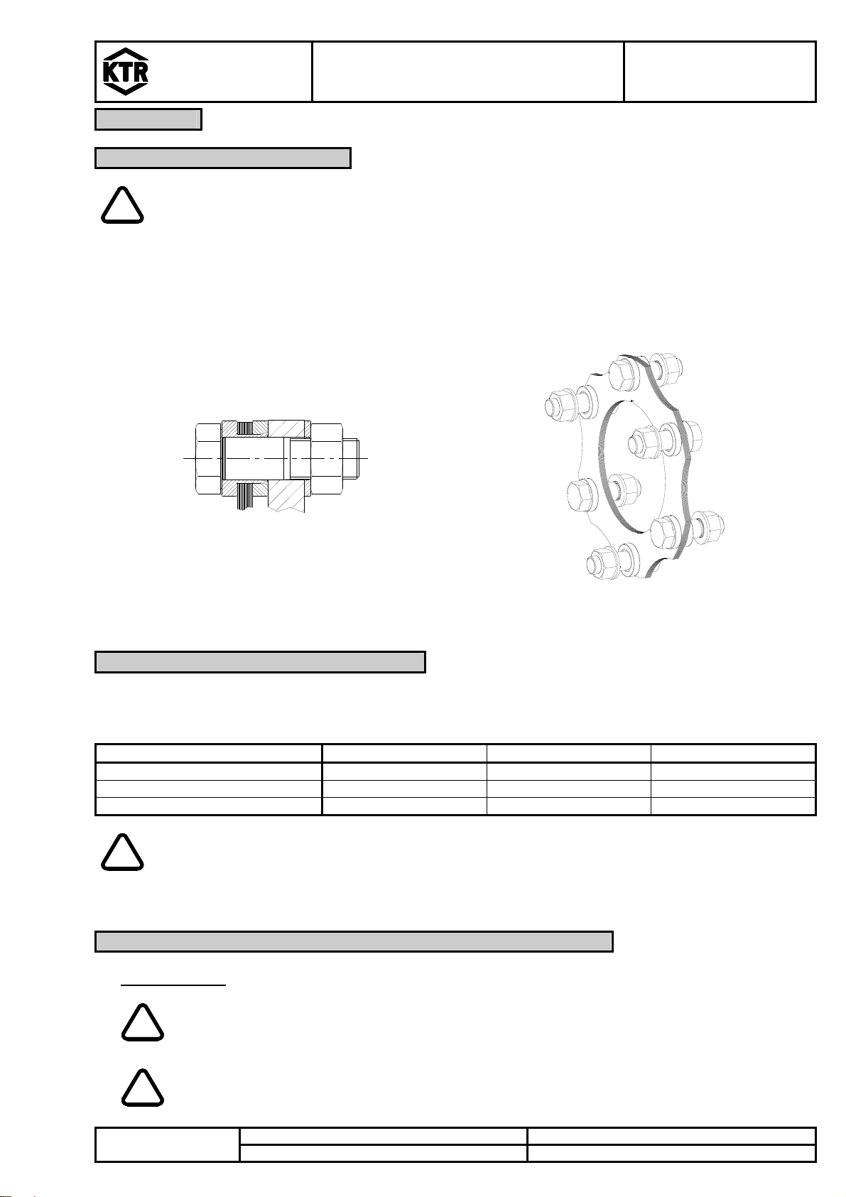
1 Technical data
DATAFLEX®torque measuring shaft
Illustration 1: DATAFLEX®torque measuring shaft
Table 1: Dimensions
DATAFLEX
type Dimensions [mm]
d D L1L
2L
3L
4L
5
85/2000 85 215 344 90 164 153 10
85/5000
85/10000
Table 2: Technical data
Coupling size DATAFLEX
85/2000 85/5000 85/10000
Electrical data
Nominal torque TKN [Nm] -2000 .. +2000 Nm -5000 .. +5000 Nm -10000 .. +10000 Nm
Band width of torque signal [kHz] (-3dB) 16
Error in linearity incl. hysteresis [%]
< ±0,5
Influence of temperature [%/10K] 0,5
Nominal temperature range [°C] 0 - 55
Supply voltage [V] DC 24 ± 4
Max. current consumption [mA] 100
Torque output
Output voltage torque [V] 0 ... 10
Output current torque [mA] 4 ... 20
Speed output
Number of impulses / revolution 60
Amplitude [V] 24/5V
DC speed output [V] 0 - 10
Scale of direct voltage output 16 settings via micro switch
Inaccuracy of DC output [%]
± 0,2
Direction signal [V] to be omitted
Mechanical data
Static load limit TKmax.
[%] 150
Breaking load TK break
[%] 300
Max. bending torque [Nm] 380 760 1270
Max. radial force [N] 1500 3000 5000
Max. axial force [kN] 50 80 110
Weight [kg] 22,6 23,3 23,9
Torsion spring stiffness CT[Nm/rad] 382000 818570 1273330
Torsion angle with TKN [degrees] 0,30 0,35 0,45
Mass moment of inertia [kgmm
] 16360 16790 17420
Max. speed [rpm] 2500
1) Referring to rated torque TKN
2) With connection housing DF2
3) Referring to measuring range value