Summarized assembly instructions
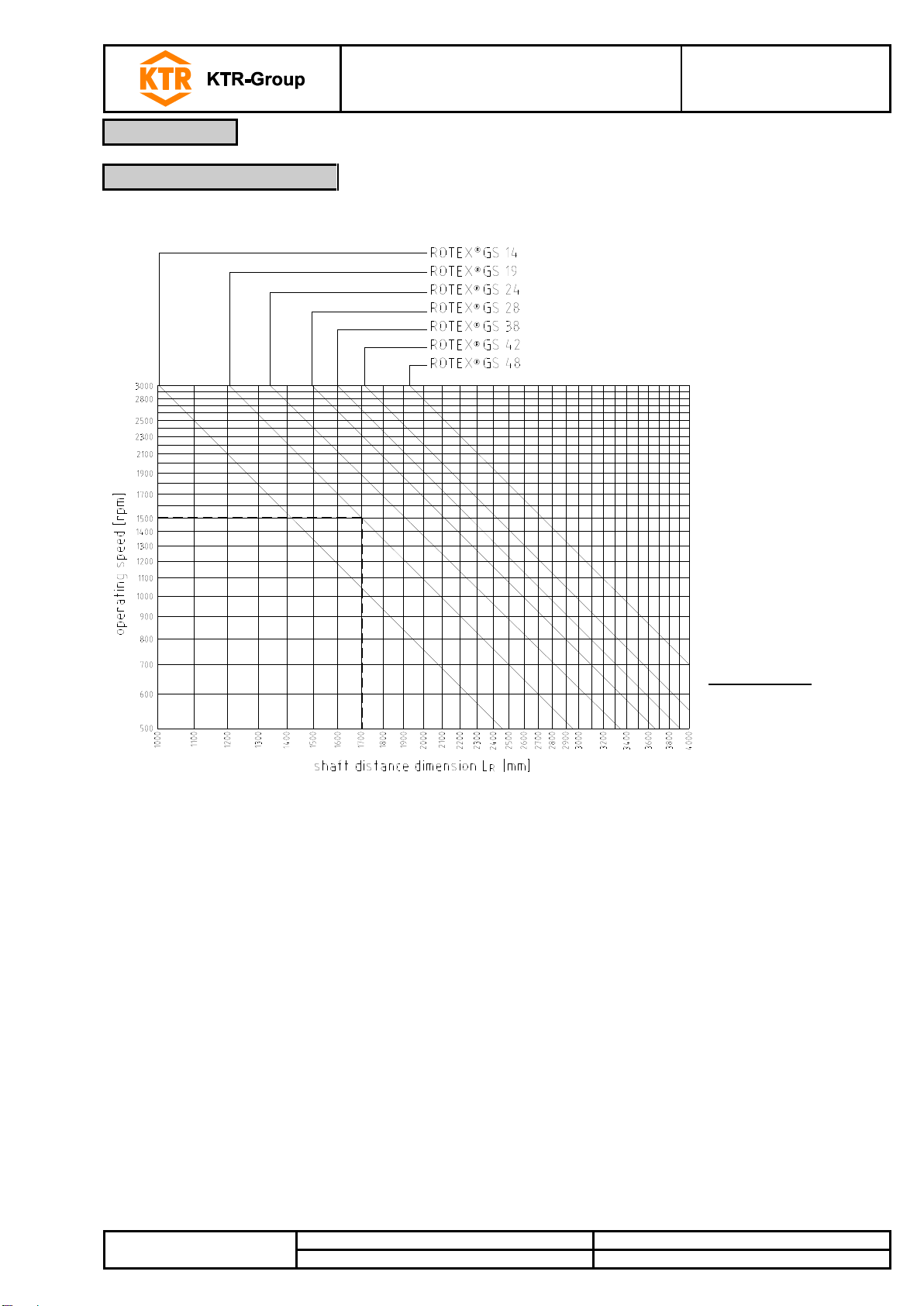
ROTEX®GS
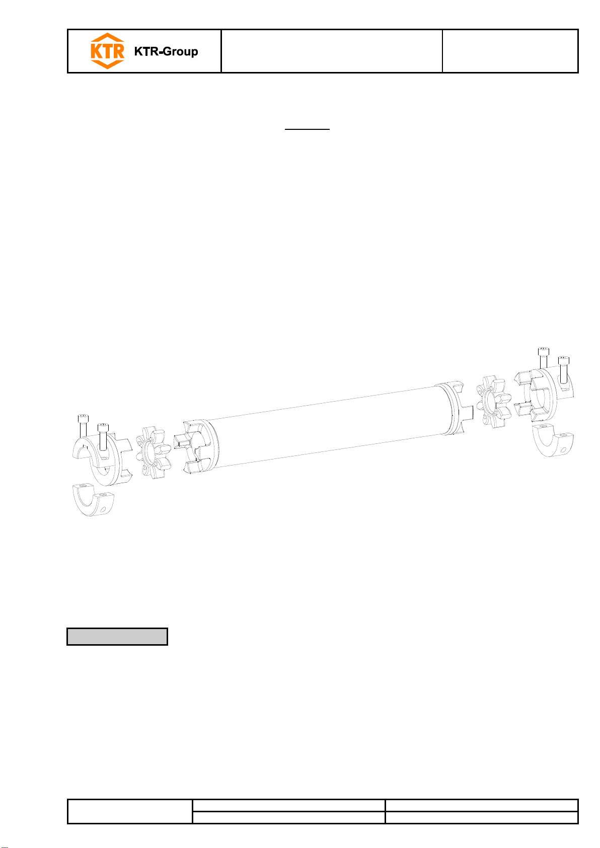
ZR3
Please observe protection
note ISO 16016.
Disassemble the cap screws of the half shell clamping hubs. Store the clamping components and cap screws
carefully.
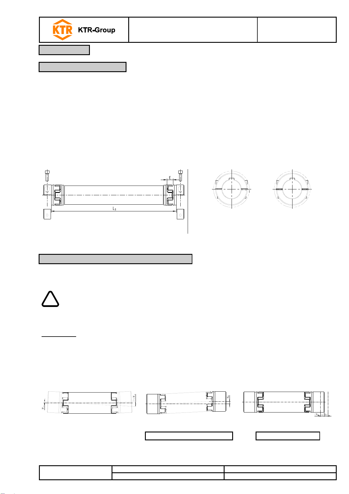
Insert the spiders into the basic body of the hub.
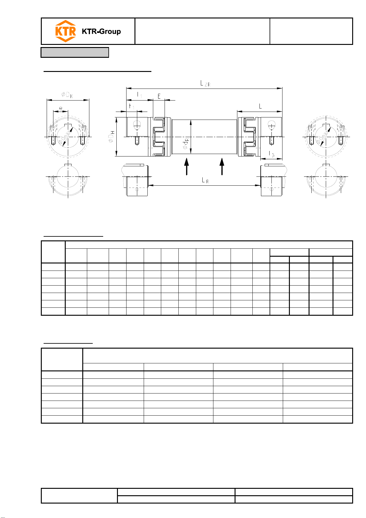
Fit the intermediate pipe between the two basic bodies of the hubs. The tapping of the basic bodies of the
hubs should point to the same direction. Here dimension LRis the shaft distance dimension. The distance di-
mension E shown in table 1 has to be observed.
Insert the coupling between driving and driven side.
Mount the clamping components to the basic bodies of the hubs. Secure the half shell clamping hubs by tight-
ening the cap screws DIN EN ISO 4762 evenly at the tightening torques TAspecified in table 3. Make sure that
the gap between the basic body of the hub and the clamping components has roughly the same width.
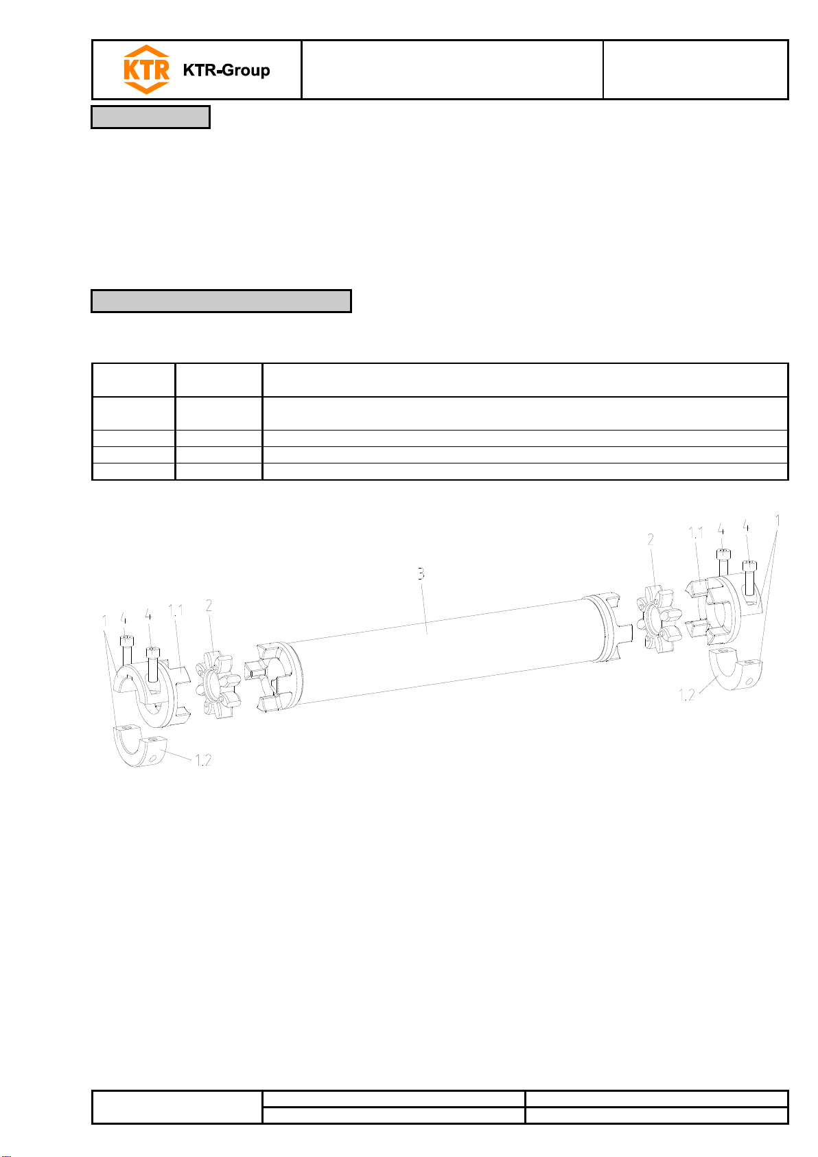
Illustration 3: Assembly of type ZR3
Illustration 4: Gap between basic body of the hub and clamping
component
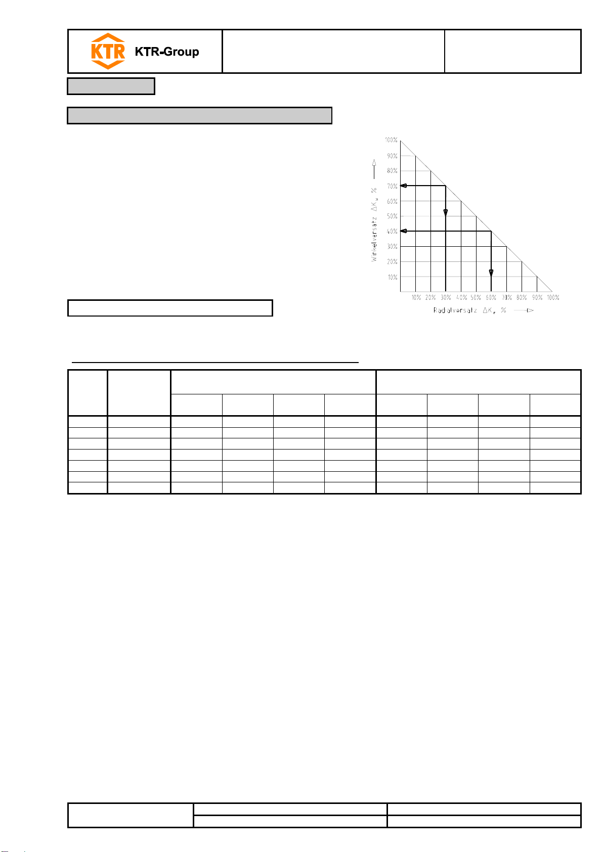
The displacement figures specified in table 4 provide for sufficient safety to compensate for external influences
like, for example, thermal expansion or foundation settling.
In order to ensure a long service life of the coupling, the shaft ends have to be accurately
aligned.
Please absolutely observe the displacement figures specified (see table 4). If the figures are
exceeded, the coupling will be damaged.
The more accurate the alignment of the coupling, the longer is its service life.
Please note:
The displacement figures specified in table 4 are maximum figures which must not arise in parallel. If radial
and angular displacements arise at the same time, the permissible displacement values may only be used
proportionally.
Please inspect with a dial gauge, ruler or feeler gauge whether the permissible displacement figures specified
in table 4 can be observed.
Kr = (LZR - 2 • l1- E) • tan α
Illustration 5: Displacements
2.3 Displacements - alignment of the couplings