KYOWA DTT-A-100 User manual
IM-T-286D Jun. 2021
DTT-A-100 DISPLACEMENT TRANSDUCER INSTRUCTION MANUAL
Thank you for purchasing the KYOWA product. Before using it, read this
instruction manual carefully. Also, keep the manual within easy reach so that
you can refer to whenever necessary.
Specifications and dimensions described in this manual could be changed
without notice. Please visit our website for the latest version.
1. Calling the operator’s attention
The following cautionary symbols and headlines are used to invite the
operator’s attention. Be sure to observe the accompanying precautions in
order to safeguard the operator and preserve the performance of the
instrument.
Warning Improper handling can cause serious injury to the
operator.
Caution Cautions are given to invite the operator’s attention, in
order to avoid instrument failure or mal-function.
2. Important notice
Unless specified, the transducer must not be used under hydrogen
environment.
3. Safety Precautions
Warning
●
As you push the rod inward, the rod returns to its initial position by
reaction force. Handle the product with care to avoid eye poking.
4. Handling Precautions
Caution
●
Do not apply excessive axial or bending force on the rod.
●
Do not rotate the rod. (For replacing accessories, see 9.)
●
Do not disassemble the product.
●
Do not use the product under water and dusty environment.
●
Use the product under environment without vibration.
●
Pay similar attentions toward the product as one gives to regular dial
gages.
●
Always keep the rod clean.
●
Make sure that the bending radius of cable is longer than 10 times of a
diameter of the cable.
5. Installation
5.1 Fix the DTT-A to the fixed point by using the accessory 2 mounting bands
(FXBP-100A), 2 wing bolts (M4×12) and M6 bolt.
The M6 bolt is not included.
5.2 Make sure the displacement of 0.5 mm or more is applied to the DTT-A.
5.3 The DTT-A and dial gage measures data by contacting the probe onto
the measuring point. However, some DTT-A rods may not track dynamic
data correctly. Make sure the rods works correctly.
5.4 To fix the rod to the measuring point, remove the prove and fix the rod to
the measuring point by using a screw (M2.5).
5.5 To measure displacement by pulling the rod, connect the accessory
adapter into the rod end.
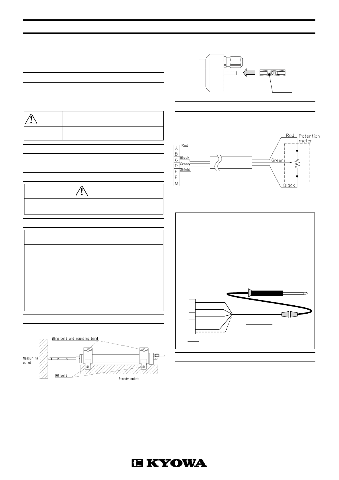
6. Connection
6.1 Connect the DTT-A to a measuring instrument.
6.2 Connect the connector plug as follows.
(Shield is not connected to the chassis.)
6.3 After the power ON, always preheat the product for approximately 5 to 10
minutes.
Caution
When using the UCAM series, since the output terminals of the DTT-A
do not match with that of the UCAM series, you are not able to connect
the connector plug. In this case, connect the conversion cable (U-17,
bared at the tip, optional). Connect the green wire (output +) into the B
terminal of the UCAM series. Since the white wire outputs no data,
connect the shield wire and white wire. Connect the white wire (no
output) into the E terminal of the UCAM series. Make sure the measuring
mode of the UCAM series is “Potentiometer-type displacement
transducer.”
7. Conversion
7.1 Use the calibration constant described on the Test Data Sheet to convert
a measured value into a displacement value.
7.2 You are able to calculate a displacement value by using the measured
value and calibration constant described on the Test Data Sheet. The Test
Data Sheet has displacement, corresponding to 1 (V/V). You are able to
calculate a displacement value by them.
Displacement (mm) =Output voltage (V) / Bridge excitation (V) ×
Calibration constant (mm/1V/V)
DTT-A
Connector plug
Adapter
Red: Input (+)
Green: Output (+)
Black: Input (-)
Red: Input (+)
Green: Outpu
t
A
B
C
D
E
White:
N
o output
Black: Input (-)
☆
☆
Shield
Conversion cable
UCAM
D
TT-A

8. Maintenance and inspection
8.1 Avoid water, dust and oil from the product.
8.2 Recommend calibrate the product once a year or so. (Contact your
KYOWA representative.)
8.3 If an abnormal initial value or reading appears, measure the resistance
(between red and black) and insulation resistance (100 MΩor higher).
If abnormal resistance is found, the DTT-A may be failure.
Contact KYOWA or our representatives.
Caution
●
To measure insulation resistance, apply a voltage lower than 50V to the
insulation resistance tester.
9. Standard Accessories
Mounting band: FXBP-100A
Adapter
Ballpoint probe: X-1-DT
10. Special Accessories (Optional)
Caution
Before installing probes and screws, be sure to insert the accessory pin
(φ2×20) into the rod hole. While installing probes and screws, hold the
pin tightly instead of holding the product. Do not apply excessive axial or
bending force on the rod. Or, the product may be damaged.
(Supplement)
Do not rotate the probe by holding the product. Do not rotate the rod.
Or, the product may be damaged.
10.1 To install the replacement probe (optional), use the spring washer and
plain washer.
10.2 After installing the replacement probe or extension rod (optional), some
rods may not work correctly depending on the DTT-A direction. Before
measuring data, make sure the rods works correctly.
To install the replacement probe
To install the extension rod
Flat probe: XS-2-DT
Spheric probe: XS-6-DT
[NOTE]
When the object to be measured is sphere, use the XS-5-DT and XS-2-DT.
Pin (φ2×20)
Probe Rod
Error!
Spheric probe: XS-105-DT
Flat probe: XS-5-DT
DTT-A

Roller-equipped probe: SH-2-DT
Extension rod
Conversion cable: U-17
4-conductor (0.3mm2) chloroprene shielded cable, 7.6mm diameter by
0.5m long, terminated with a connector plug PRC03-32A10-7F and bared
at the tip.

Website : www.kyowa-ei.com
11. Outside Drawing
12. Specifications
◆Performance
Rated Capacity 100 mm
Nonlinearity Within ±0.2%RO
Hysteresis Within ±0.2%RO
Repeatability 0.1%RO or less
Rated Output 0.9V/V ±10%(Voltage Output)
◆Environmental Characteristics
Safe Temperature -10 to 70℃(Non-condensing)
Compensated Temperature 0 to 60℃(Non-condensing)
Temperature Effect on Zero Within ±0.05%RO/℃
Temperature Effect on Output Within ±0.05%/℃
◆Electrical Characteristics
Safe Excitation 36 VDC (23℃)
Recommended Excitation 2 to 10 VDC
Resistance 1kΩ±20%
Cable 4-conductor (0.08mm2) vinyl shielded
cable, 3.2mm diameter by 1m long,
terminated with a connector plug
(PRC03-12A10-7M)
(Shield is not connected to the
chassis.)
◆Mechanical Properties
Frequency Response DC to 6Hz(When the tip is touching to
the testing machine, displacement :
100mm)
(Reference : DC to approx. 50Hz,
when the tip is fixed,
displacement:30mm)
Measuring Force Approx. 5 N
Weight Approx.110g (Excluding Cable)
Degree of protection IP40 (IEC 60529)
Compliance Directive 2011/65/EU, (EU) 2015/863
(10 restricted substances) (RoHS)
[NOTE]
Products with CE Marking are compliant European RoHS Directive.
◆Accessories
Adapter 1
Pin (φ2×20) 1
Ballpoint probe (X-1-DT) 1
Mounting band (FXBP-100A) 2
Mounting band 1
Wing bolt (M4×12) 1 ×2
Plain washer (M4) 1
Test Data Sheet 1
Instruction manual 1 (This book)
◆Optional Accessories
Extension Rods EB-50,100,200,300
Mounting Band FXBP-100A
Replacement Probes X,XS,SH
Other KYOWA Transducer manuals

KYOWA
KYOWA PG-2KU User manual

KYOWA
KYOWA DTH-A User manual

KYOWA
KYOWA DTK-A User manual

KYOWA
KYOWA DTPA-A-5K User manual

KYOWA
KYOWA ASH-A-10 User manual

KYOWA
KYOWA DTC-A User manual

KYOWA
KYOWA PHF-S-SA4 User manual

KYOWA
KYOWA DTS-A-100 User manual

KYOWA
KYOWA PG-1TH User manual

KYOWA
KYOWA PGM-D Series User manual

Popular Transducer manuals by other brands


Mianyang Weibo Electronic
Mianyang Weibo Electronic WB Series user manual

ProMinent
ProMinent Dulcometer DMT operating instructions

MKS
MKS MicroPirani 925 Series Short form manual

WIKA
WIKA WU-20 operating instructions

Alcatel Vacuum Technology
Alcatel Vacuum Technology BARATRON 622A instruction manual

Camille Bauer
Camille Bauer SIRAX CH-5610 operating instructions


