manuals.online logo
Brands
  1. Home
  2. •
  3. Brands
  4. •
  5. KYOWA
  6. •
  7. Transducer
  8. •
  9. KYOWA ASH-A-10 User manual

KYOWA ASH-A-10 User manual

IM-T-303 Mar. 2020
ASH-A
Acceleration Transducers INSTRUCTION MANUAL
Thank you for purchasing this KYOWA product. Before using it, please read this
instruction manual carefully. Also, keep the manual within easy reach so that you
can refer to whenever necessary.
Specifications and dimensions described in this manual could be changed without
notice. Please visit our website for the latest version.
1. Calling the operator’s attention
Be sure to observe the accompanying precautions in order to safeguard the
operator and preserve the performance of the instrument.
Warning Improper operation of the system may result in severe
injury of the operator.
Caution It is a precaution to operate properly.
2. Safety precautions
Warning

Be sure to mount the product properly.
If the product loosens while using it, the product may be detached or
damaged, and operators may be damaged.
3. Mounting
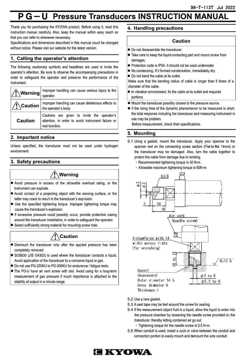
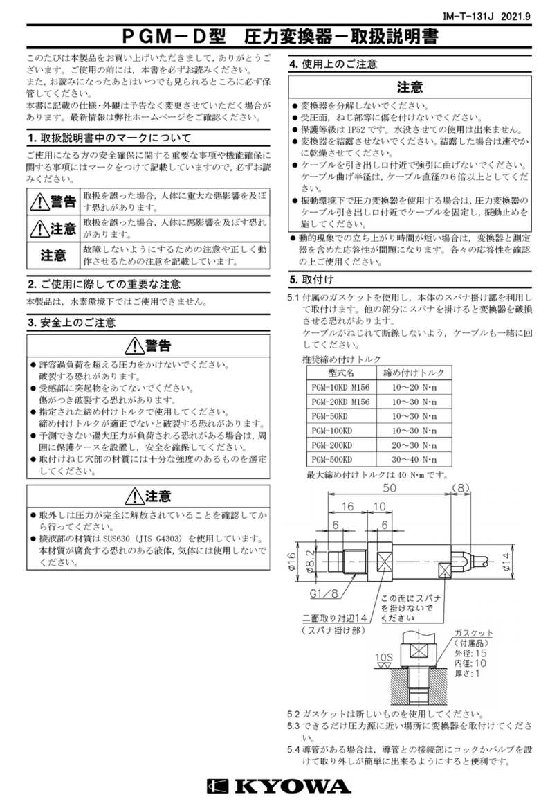
3.1 The dimensions of each transducer are illustrated below.
To mount the transducer, carefully align its sensing direction with the direction
of acceleration and use adhesive.

Outline drawing of the ASH-A-10 to 50
Indicates the center of mass of the acceleration transducer.

Outline drawing of the ASH-A-100 to 1K
.Indicates the center of mass of the acceleration transducer.
3.2 Thoroughly clean the bonding area of the measuring object. Remove dust, oil
and rust from the area using sandpaper and acetone.
Also, thoroughly clean the mounting surface of the transducer.
3.3 Fix with adhesive (cyanoacrylate instantaneous adhesive etc.).
3.4 Be sure to fix the cable to the measurement object as much close as
possible to the transducer mainframe. If circumstances do not allow to fix the
cable to the measurement object, let the cable to slack in such a manner that
it will not be pulled after mounting.
3.5 The transducer cannot be mounted to a curved surface. Use a jig or prepare
a flat mounting area on the curved surface.
3.6 The polarity of transducer output against acceleration
The relation between the direction of acceleration applied to the transducer
and the polarity of transducer output are illustrated below.
Caution
Do not disassemble the transducer.
The transducer is very sensitive to shocks. If the transducer is dropped or hit
by a hard matter, thus receiving impact in excess of the allowable overload
rating, damage may be caused. To avoid harm, be sure to handle it very
carefully.
After the transducer fixation, avoid plucking the cable, swinging around
having a cable, if not, the transducer may be disconnection. Take great care
to handle it properly.
Install the transducer carefully because its frequency characteristics may vary
depending on the state of installation. The ideal installation is such that the
transducer completely and firmly adheres to a measuring object. Avoid such
manners as to subject the transducer to a bending or twisting force.
The transducer is not waterproof, therefore avoid using it where it may be
exposed to water or in environments whose humidity is over 85 %.
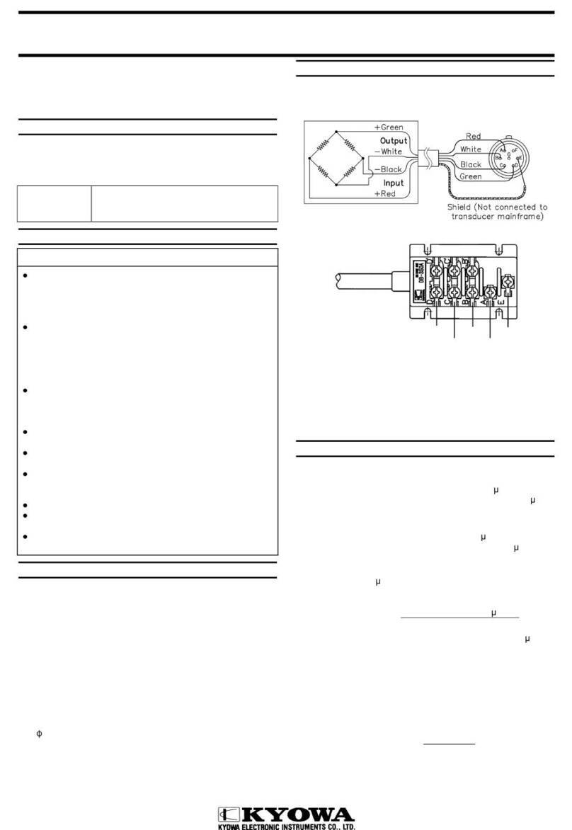
4. Connection
4.1 Connect the transducer to a strain amplifier.
4.2 Observe the pin assignment of the connector illustrated below.
Caution
A bridge excitation voltage should be in a range of 2 V. A bridge excitation
voltage other than 2 V does not satisfy the specifications.
Be sure to start measurement 5 minutes or a longer time after power was
switched on.
Website: https://www.kyowa-ei.com/
5. Dismounting
5.1 To dismount the ASH-A which was bonded with the adhesive, apply a solvent,
to the bonding area then leave it as it is for about 2 minutes. Next, apply the
tip of a screwdriver to the bonding position and softly push the screw-driver
grip up and down. If this does not work, apply the sol-vent anew and repeat
the same procedure.
Avoid forcible dismounting, or deterioration of the ASH-A characteristics or
breakdown may be caused.
6. Conversion
6.1 To convert output, use the calibration constant stated in the Test Data Sheet.
6.2 When a strain amplifier is used, a measurement value is read in ε×10-6 strain.
The acceleration is shown as follows using the reading value and the
calibration constant.
Acceleration (m/s2)
=Reading of strain amplifier (ε×10-6 strain)
×Calibration constant (m/s2/1×10-6 strain)
6.3 If you use an amplifier of other type, it is necessary to measure the applied
bridge excitation voltage accurately. The Test Data Sheet states the
acceleration value which corresponds to 1 μV output against 1 V bridge
voltage applied.
Acceleration(m/s2)= Bridge output voltage(μV)
Bridge excitation voltage(V)
×Calibration constant (m/s2/1μV/V)
Reference
The relation between acceleration vibration and amplitude is as follows.
Acceleration (m/s2)=a4π2f2
where,a:Amplitude (m)
f:Vibration (Hz)
7. Storing precautions and inspection
7.1 Avoid water, oil and dust on the connector.
7.2 After use, clean the transducer and store in the accessory case.
7.3 If the initial value and/or reading value are found abnormal, measure
input/output resistance and insulation resistance (which should be 100 MΩ).
If the measured values differ from the calibration sheet, the cause may be
failure of the sensing element. In this case, contact KYOWA or our
representatives.
Caution
To measure insulation resistance, apply a voltage lower than 50V DC to the
insulation resistance tester.
8. Specifications
Models Rated capacity
(Reference value)
Frequency Response
(At 23℃)
ASH-A-10 ±98.07 m/s2
(±10G)
DC to 500Hz
(Sensitivity deviation:±5%)
ASH-A-20 ±196.1 m/s2
(±20G)
DC to 650Hz
(Sensitivity deviation:±5%)
ASH-A-50 ±490.3 m/s2
(±50G)
DC to 1.5kHz
(Sensitivity deviation:±5%)
ASH-A-100 ±980.7 m/s2
(±100G)
DC to 2kHz
(Sensitivity deviation:±5%)
ASH-A-200 ±1961 m/s2
(±200G)
DC to 3.5kHz
(Sensitivity deviation:±5%)
ASH-A-500 ±4903 m/s2
(±500G)
DC to 5kHz
(Sensitivity deviation:±10%)
ASH-A-1K ±9807 m/s2
(±1000G)
DC to 7kHz
(Sensitivity deviation:±10%)
◆Performance
Rated Capacity :See table above.
Nonlinearity :Within ±1%RO
Hysteresis :Within ±1%RO
Rated Output :0.5 mV/V (1000×10-6 strain) ±25%
(ASH-A-10)
0.5 mV/V (1000×10-6 strain) ±20%
(ASH-A-20 to 1K)
◆Environmental Characteristics
Safe Temperature Range :-15 to 65℃
Compensated Temperature Range
:5 to 40℃
Temperature Effect on Zero Balance
:Within ±1%RO/℃
Temperature Effect on Output
:Within ±1%/℃
◆Electrical Characteristics
Safe Excitation voltage :6V AC or DC
Recommended Excitation voltage
:2V AC or DC
Input Resistance :120Ω±5% (ASH-A-10 to 50)
120Ω±8.3%(ASH-A-100 to 1K)
Output Resistance :120Ω±5% (ASH-A-10 to 50)
120Ω±8.3%(ASH-A-100 to 1K)
Cable :4-conductor(0.08mm2) vinyl shielded cable,
3.2mm diameter by 5m long, terminated with
connector plug (PRC03-12A10-7M)
(Shield wire is not connected to the case.)
◆Mechanical Properties
Safe Overload Rating :300 %
Frequency Response :See table above.
Transverse Sensitivity :2%RO or less
Weight :Approx. 13g (ASH-A-10 to 50)
(Excluding Cable) Approx. 6.5g (ASH-A-100 to 1K)
◆Accessories
Instruction manual :1 (This book)
Test data sheet :1
IM-T-303 2020.3
ASH-A型 加速度変換器-取扱説明書
このたびは本製品をお買い上げいただきまして,ありがとう
ございます。ご使用の前には,本書を必ずお読みください。
また,お読みになったあとは,いつでも見られるところに必
ず保管してください。
本書に記載の仕様・外観は予告なく変更させていただく場合
があります。最新情報は弊社ホームページをご確認ください。
1. 取扱説明書中のマークについて
ご使用される方の安全確保に関する重要な事項や機能確保に
関する事項にはマークをつけて記載していますので、必ずお
読みください。
警告 取扱を誤った場合,人体に重大な悪影響を及ぼ
す恐れがあります。
注意 正しく動作させるための注意です。
2. 安全上のご注意
警告

本製品の取り付けが不十分な場合,衝撃により外れた本製
品が当たって怪我をする恐れがあります。取り付け方法を
守ってご使用ください。
3. 取り付け
3.1 外観寸法は下図のようになっています。
感度方向を正しく合わせ,接着剤により取り付けます。
ASH-A-10~50 外観図
は,変換器本体の質量中心を示す。
ASH-A-100~1K 外観図
は,変換器本体の質量位置を示す。
3.2 取り付け場所を十分に洗浄してください。ゴミ,油,錆
はサンドペーパーおよびアセトンで十分取り去ってくだ
さい。
変換器本体側の取り付け面も十分に洗浄してください。
3.3 接着剤(シアノアクリレート系瞬間接着剤など)で接着
してください。
3.4 ケーブルはできるだけ変換器本体に近い所で被測定体に
固定してください。なお,やむを得ず被測定体に固定で
きない時は引っ張られない程度にたるみをもたせて固定
してください。
3.5 円曲部への接着取り付けは出来ません。治具を使用する
か、または接着部をフラットにして取り付けてください。
3.6 加速度に対する出力の極性
加速度の入力条件と本体の矢印表示の関係は、下記のよ
うになっています。
注意

本製品を分解しないでください。

本製品は衝撃に対して敏感に出来ています。落としたり,
硬いものにぶつけるなど,許容過負荷を超える衝撃を本体
に与えた場合、破損する恐れがあります。

変換器本体を固定後にケーブルを引っ張ったり,ケーブル
を持って振り回すと断線する恐れがあります。

本製品の取り付けは,その状態により周波数特性が変化す
る場合があります。被測定物と完全密着した取り付けが理
想的であり,変換器本体に曲げやねじりなどの外力が加わ
るような取り付けは良くありません。

本製品は防水処理を施していないので,水のかかる場所や
湿度 85%以上の環境下では使用できません。
4. 接続・測定
4.1 本製品をひずみ測定器に接続します。
4.2 コネクタへの配線は下図のようになっています。
注意

印加電圧は 2V にしてください。2V 以外では仕様を満足し
ません。

電源投入後5分以上経ってから測定を開始してください。
ホームページアドレス https://www.kyowa-ei.com/
5. 取り外し
5.1 接着剤で取り付けた変換器本体を外す場合,溶剤を接着
部に塗布して2分位放置します。ドライバの先端で軽く
上下させて外します。簡単に取れない場合は再度溶剤を
塗布して行います。
無理な力をかけて外すと特性が悪くなったり,故障の原
因となる場合があります。
軽く上下させる。 ドライバ先端部の厚みは 0.5mm 以下
を使用してください。
6. 出力換算
6.1 出力の換算には検査成績書の校正係数を使用します。
6.2 ひずみ測定器を使用する場合は出力がε(×10-6 ひずみ)
で表示されます。1(×10-6 ひずみ)に相当する加速度が
検査成績書に記入されていますので乗算により加速度が
求められます。
[加速度(m/s2)]
=[ひずみ測定器の出力ε(×10-6 ひずみ)]
× [校正係数(m/s2/1×10-6 ひずみ)]
6.3 その他の増幅器,記録器を使用する場合はブリッジ印加
電圧を正確に計ることが必要になります。検査成績書に
はブリッジ印加電圧 1(V)を加えたときの出力電圧
1(μV)に相当する加速度が記入されています。
[加速度(m/s2)]
= ブリッジ出力電圧(μV)
×校正係数(m/s2/1μV/V)
ブリッジ印加電圧(V)
64
参考
加速度,振動数,振幅は次の関係になります。
加速度(m/s2)=a4π2f2
a:片振幅 (m)
f:振動数 (Hz)
7. 保管上の注意および点検
7.1 コネクタには水,油,塵などがつかないようにしてくだ
さい。
7.2 使用後は汚れを取り,収納ケースに保管してください。
7.3 初期値,指示値が異常と思われる場合は,入力抵抗,出
力抵抗,本体とケーブル心線間の絶縁抵抗(100MΩ以上)
を測定してください。
測定値が異常の場合,本器の故障と考えられます。弊社
営業までご連絡ください。
注意

絶縁抵抗を測定する場合には、絶縁抵抗計の印加電圧は
50V DC 以下で行ってください。
8. 仕様
型式名 定格容量
(参考値)
応答周波数範囲
(23℃)
ASH-A-10 ±98.07 m/s2
(±10G)
DC~500Hz
(感度偏差±5%)
ASH-A-20 ±196.1 m/s2
(±20G)
DC~650Hz
(感度偏差±5%)
ASH-A-50 ±490.3 m/s2
(±50G)
DC~1.5kHz
(感度偏差±5%)
ASH-A-100 ±980.7 m/s2
(±100G)
DC~2kHz
(感度偏差±5%)
ASH-A-200 ±1961 m/s2
(±200G)
DC~3.5kHz
(感度偏差±5%)
ASH-A-500 ±4903 m/s2
(±500G)
DC~5kHz
(感度偏差±10%)
ASH-A-1K ±9807 m/s2
(±1000G)
DC~7kHz
(感度偏差±10%)
◆性能
定格容量 :上記表参照
非直線性 :±1%RO 以内
ヒステリシス :±1%RO 以内
定格出力 :0.5mV/V(1000×10-6 ひずみ)±25%
(ASH-A-10)
0.5mV/V(1000×10-6 ひずみ)±20%
(ASH-A-20~1K)
◆環境特性
許容温度範囲 :-15~65℃
温度補償範囲 :5~40℃
零点の温度影響 :±1%RO/℃ 以内
出力の温度影響 :±1%/℃ 以内
◆電気的特性
許容印加電圧 :6V AC または DC
推奨印加電圧 :2V AC または DC
入力抵抗 :120Ω±5% (ASH-A-10~50)
120Ω±8.3% (ASH-A-100~1K)
出力抵抗 :120Ω±5% (ASH-A-10~50)
120Ω±8.3% (ASH-A-100~1K)
ケーブル :0.08mm2,4 心シールドビニル 5m,
外径 3.2mm,先端コネクタプラグ
(PRC03-12A10-7M)
(シールドは本体に接続されていません)
◆機械的特性
許容過負荷 :300%
応答周波数 :上記表参照
横感度 :2%RO 以下
質量 :ASH-A-10~50 約 13g(ケーブル含まず)
ASH-A-100~1K 約 6.5g(ケーブル含まず)
◆付属品
取扱説明書 :1部(本書)
検査成績書 :1部
( )

This manual suits for next models

6

Other KYOWA Transducer manuals

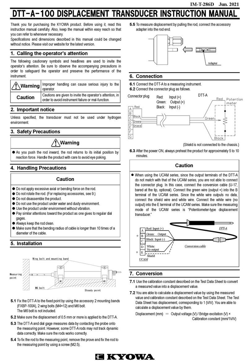
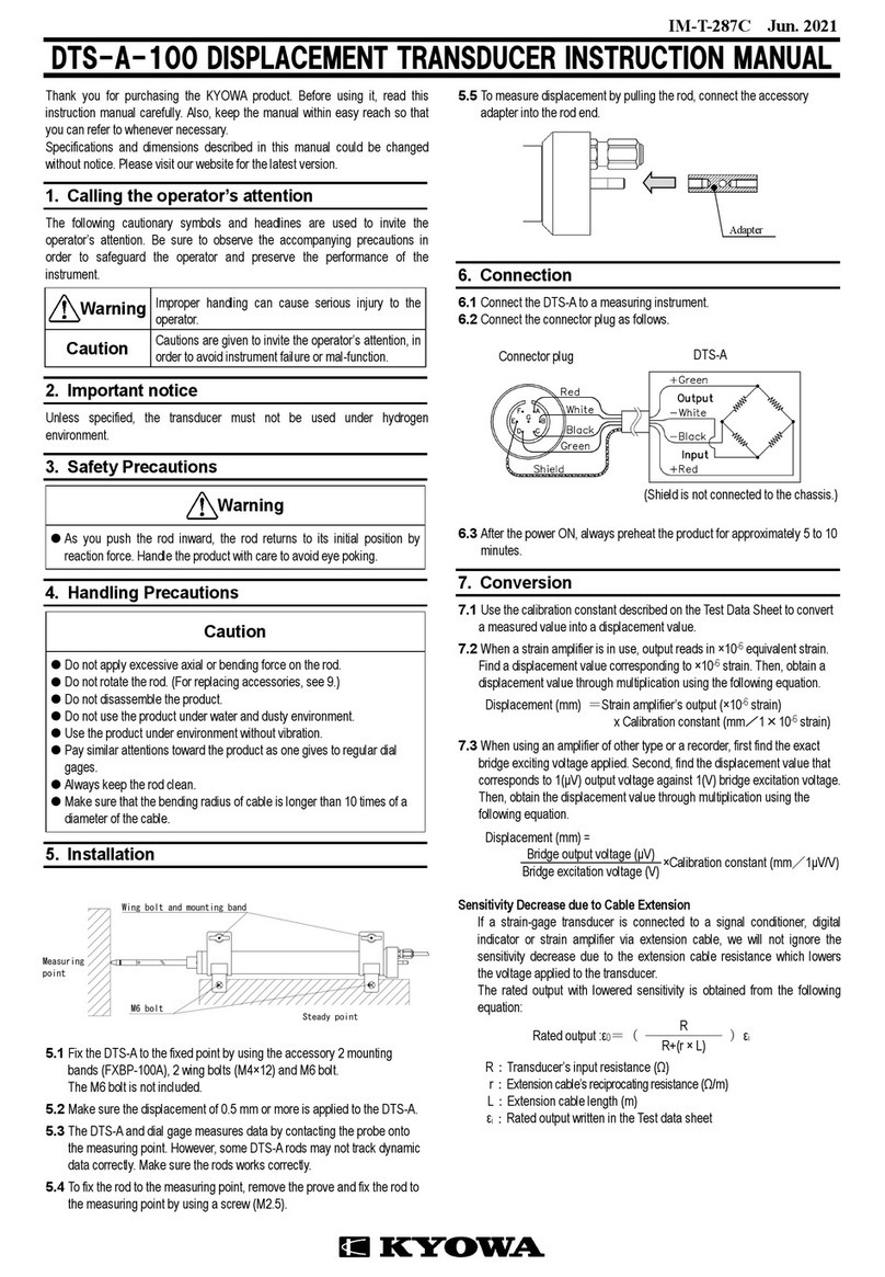
KYOWA DTS-A-100 User manual

KYOWA

KYOWA DTS-A-100 User manual

KYOWA BER-A-15S User manual

KYOWA

KYOWA BER-A-15S User manual

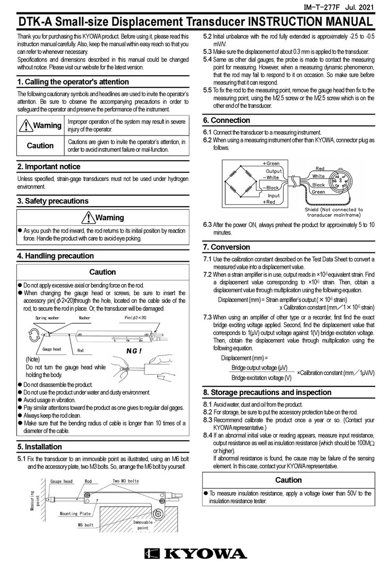
KYOWA DTK-A User manual

KYOWA

KYOWA DTK-A User manual

KYOWA DTPA-A-5K User manual

KYOWA

KYOWA DTPA-A-5K User manual

KYOWA PG-1TH User manual

KYOWA

KYOWA PG-1TH User manual

KYOWA PG-2KU User manual

KYOWA

KYOWA PG-2KU User manual

KYOWA DTC-A User manual

KYOWA

KYOWA DTC-A User manual

KYOWA DTT-A-100 User manual

KYOWA

KYOWA DTT-A-100 User manual

KYOWA PGM-D Series User manual

KYOWA

KYOWA PGM-D Series User manual

KYOWA DTH-A User manual

KYOWA

KYOWA DTH-A User manual

KYOWA PHF-S-SA4 User manual

KYOWA

KYOWA PHF-S-SA4 User manual

Popular Transducer manuals by other brands

B-K Medical Type 8553 user guide

B-K Medical

B-K Medical Type 8553 user guide

HYDACELECTRONIC HLT 1100 Series Assembly instructions

HYDACELECTRONIC

HYDACELECTRONIC HLT 1100 Series Assembly instructions

Sensor Technology TorqSense SGR510 Series user manual

Sensor Technology

Sensor Technology TorqSense SGR510 Series user manual

Axxeron HESCH HE 5411 operating instructions

Axxeron

Axxeron HESCH HE 5411 operating instructions

Raymarine DownVision CPT-70 installation instructions

Raymarine

Raymarine DownVision CPT-70 installation instructions

Veeder-Root PLLD installation guide

Veeder-Root

Veeder-Root PLLD installation guide

norbar PNEUTORQUE PT 1 Operator's manual

norbar

norbar PNEUTORQUE PT 1 Operator's manual

Simrad 12-16/60 datasheet

Simrad

Simrad 12-16/60 datasheet

S+S Regeltechnik THERMASGARD ALTM Operating Instructions, Mounting & Installation

S+S Regeltechnik

S+S Regeltechnik THERMASGARD ALTM Operating Instructions, Mounting & Installation

Sofraser 9000 Technical manual

Sofraser

Sofraser 9000 Technical manual

GO Systemelektronik BlueSense manual

GO Systemelektronik

GO Systemelektronik BlueSense manual

Camille Bauer Gossen MetraWatt SINEAX DME 401 operating instructions

Camille Bauer

Camille Bauer Gossen MetraWatt SINEAX DME 401 operating instructions

Camille Bauer SIRAX BT5400 Device handbook

Camille Bauer

Camille Bauer SIRAX BT5400 Device handbook

Ruskin AMS Series Installation and operation instruction

Ruskin

Ruskin AMS Series Installation and operation instruction

Iskra MI 401 user manual

Iskra

Iskra MI 401 user manual

Mianyang Weibo Electronic WB9128-1 user manual

Mianyang Weibo Electronic

Mianyang Weibo Electronic WB9128-1 user manual

HBM AD101B quick start guide

HBM

HBM AD101B quick start guide

Camille Bauer SIRAX CH-5610 operating instructions

Camille Bauer

Camille Bauer SIRAX CH-5610 operating instructions

manuals.online logo
manuals.online logoBrands
  • About & Mission
  • Contact us
  • Privacy Policy
  • Terms and Conditions

Copyright 2025 Manuals.Online. All Rights Reserved.