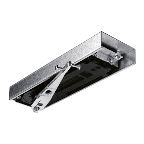
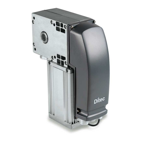
Sesamo PIUMA User manual

PIUMA
Automatism
for
swinging
doors
INSTALLATION
INSTRUCTIONS
ffin@'ffi

We thankyou for having chosenthis product.In orderto get the bestperformance
from the device,Sesamo
recommendsthat
youread
and
follow carefullytheinstructionsfor installation
andusecontainedin thismanual.
Do not litter the environmentwith the packingmaterialswhich may be a sourceof hazard
for childrenand
animals.
Theinstallation
mustbecarriedoutby qualified
staffin conformitywith theregulationsin force.
Payparticular
attention
to themessages
containedin thismanual
and
marked
by thedangersymbol.Thesemay
either be wamingsto avoid potentialdamageto the apparatus,
or specificsignalsof potentialhazardfor the
safetyofthetechnician
orother
people
involved.
GENERAi,L
Read
thismanual
carefullybefore
proceeding
to the installation,stalt-upor maintenance
of theapparatus.
This
device
has
beenconceived
to automate
pedestrian
swingingdoors;anyotheruseshallbeconsideredcontraryto
theuseforeseenbythemanufacturer
who cannotbeliablefor damages
to people
orthings.
Beforetheinstallation,
checkthatthedoorto be automatedhasa uniform andfrictionless
openingandclosing
movement.
Checkthat the fixing surfaceis level and smoothso asto avoid deformations
to the baseof the
automatism
andthatit is of asuitablesizefor astable
fixing of theapparatus.Eliminateanyspringdoor-closing
devices
previouslyinstalled.The builder is not liable for anydeformationto the automatedfixture dueto the
inadequatefirmness
of theframe.
DESCR|,PTIONOF THEA,UTOMATISM
To reachtheinternal
parts
of theautomatism,remove
themetalliccapby levering
with a suitable
point-shaped
tool on the end sides.Pay particularattentionwhen removingthe cap so asto avoid damage
to the covering
parts.
Theautomatismiscomposedof:
l. Aluminiumfixingbase
2. Aluminiumendsides
3. Cap
4. Gearmotor
5. Electronicexchangemicroprocessor
1
6. Transformerwith fusible
wiringsystem.
T 630MA.
7. Encoder
group
for movementcontrol
8. Emergencybatteries
(optional)
24V-0.8Ah
9. Power
supplyterminalboard230Vac
i ,'-
.\ ,. I
ft l'" I"
I
ItF,l
]1 fl
t7-:
t?
1'\
Powersunolv 230V
AC 50Hz
Rated power 60w
Rated motor torque 23Nm
Service Continuous
> 500cycles/day,withcapacityof300cycles/hourx 2hours
Operating temperature Boxinsidefrom0"Cto+50oC
Automatismdimensions
(mm) Heieht:79 Depth:
96.5 Lensth r","a"..ni
830 Leneth s"n";"":i 925
Automatism
weieht 7.6Ks. 8.6kg ,r.*""*'
Wins width (mm) 700
+ 1200
Wins maximumweisht 150Ke
Wing max. openinqangle 100'
I

iIsEli4ilo
The automaton is prearrangedby Sesamoto
operatewith different accessory
and peripheral
configurations. According to the configuration
chosen,
setthe cables
necessary
to guarantee
all
theconnections
totheperipheral
devices.
Fig.2
showsanexample
ofone
winginstallation
in
which the opening is commandedby a radar
sensor
to enter,and
by abutton
to come
out.
The figure schematises
the most importantparts
that form the finished installation (automatic
entry)andsome
of theperipheral
devices
thatcan
be
installed:
A. Boxin aluminium
extrusion
B. Opening-closing
operating
arm
C. Drawingarm
guide
D. Entryradar
E. Safetyactive
sensor
F. Night
time
closingdevice
G. Multilogic
selector
H. Openingbutton
atexit
l
I
tu
6
Therigiddrawing
armisusedwiththeautomatism
installed
on
theopening
sideofthe
door
(fig.3-4).
Forleftopening
wings
(wing
withanticlockwise
rotation
opening),
settheautomatism
asshowninFig.3.
co-)ci,
Hinge
axis Gearmotor
axis Drawino
rioid
arm
o .u'
t-
\t/o
/t\
/ : \ WARNING: useasa reference point the axis of the wing hinges and the gearmotor operating axis.
LJ,L.
'1r . 4 :.]:l
I5a L I ao6 -T-
.|r- '1
'1* ll ]J rr.' :
t r / il -l I
)'',+=a it
:.'tI
Hinge il /
-il/ r-/
r jOO _] / Guide's
rigid
arm , -,-,
ill
1
For right openingwings (wing with clockwiserotationopening),
setthe automatism
as shownin Fig.4 (the
reverseinstallation
compared
with theleft opening). 2
I

ttsEiAilto
t-
tf
I I o Drawing
rigid
arm
tl
rj
f- -r-=\\-
I ---=---- -.-
-N -_\\ -
t\\l
O-)
N
.1.
!-) Gearmotor
axis Hinge
axis
Guide'srigid
arm
Thediameters
of theholesfor fixine arenotedin Fis. 5.
830
A WARNING the definitivetighteningof the screwsshouldbe doneonly afterhaving checked
thatthe
verticalpositioning
of theautomatismensuresthatthehingeaxisandthegearmotor
axis(Fig.3-4)are
perfectly
parallel.
Therefore,afterhavinginstalled
therigid armand
therelativeguide,check
thatduringthe manoeuwe
the drawbolt of the arm doesnot force the rylindrical runner (Fig.6 part B). Any error of positioning or
tightening of the automatismwould in fact make the drawbolt of the rigid arm oscillate,in respect
to the
cylindricalrunner,more
thantheallowabledeviation,
andwouldconsequently
damage
parts
of theautomatism.
q
a.l
qg
o6
31 300
--*
_ub.5 ab2 *J
P -+r---
-+|- l
|,
'l aa. l
--rGjt= ^ ".:
-il -=-*q'*- -
-6
60/ (l
(O
V)6 (a1
=== I
aF, I
.-.-------*l o)
l--
(o
ra
126 1
+ I
, -2,1
LJI ++46 79+
*1 q
N

trs6AI||o
INSTALLATION
OF THEDRAWINGRrctD ARM AND
OF THEGU/IDE
(FtG,
3-4-6.8)
Reachtheguide
fixing box (Fig.6partD) takingoff the S924lA,cap.Makeatleast4 holes
corresponding
to the
"V" shape
in the guideprofile (Fig.6 part D). Use theseholesto fix the guideto the framewith appropriate
screws.Insertthe cylindrical runner(Fig.6 part B), with the relative shaft,inside the guide and distributea
uniformlayerofgrease
ontheslidingarea.
Subsequently,
oncethe installationof the rigid arm desoibed in fig.7 is finished,screwthe threadedshaft,
inserted
in thecylindrical runner,in the specialholeatthe extremityof therigid arm.Closetheguide
with the
capsand
screwssupplied.
I
tr!
v
a't
,'s 92,1/A.:i
qTH'
;r+1
ffi,,',,,,
)"
@i
*i
Insertthe threadedhexagon
in the upperpart
of thehexagonalhole
of thegearmotor(Fig.7
part
A).
Assemble
therigid armto theupperhexagon
with the flathead
screwsuppliedafter having
interposed
thewashers
asshownin thefigure.
Drowing rigid arm: beforetighteningthe
flathead screw, check carefully that the
distancebetween
the guideandthe rigid arm
is about 13 mm (fie.6). It is possible
to
achieve the right distance by varying the
number of washers placed between the
hexagons previously assembled (max. 8
washers)
(Fig.7 part B). Once the required
distanceis obtained,
tighten
theflathead
screw
well.
Articulated drawing arm: before tightly
shutting the flatheadscrew, carefully check
that
theupper
partof thearticulated
armeasily
rotates under the door frame and that the
obtainabledistance,
by adjusting
the washers
(max. n. 8) betweenthe hexagons,
ranges
between 12 and 24 millimeters measured
betweenthe coverof the automatism
andthe
upper
part
ofthe articulated
arm
(Fig.9).
/_- :
l I-.
Y
\/
. rir R
tr--

iISHiAMO
ADJUSTMENT
OFTHESIOPt TSIDE
THEGUIDE
(FtG.6-8)
Insert
the
lock(Fig.6
part
C) inside
the
spline
(Fig.6part
A); openthewingtothedesiredamplifude,
thenbring
thelockin contactwiththe
cylindricalrunner
(Fig.6-8part
B) andtightenthe
screwonthelock.
The
articulated
drawingarmisusedwhen
theautomatism
isinstalled
ontheopposite
sidetothatof theopening
ofthedoor.
For left opening
wings (wings with anti-clockwise
rotationopening)setthe automation
as shownin Fig. 9,
(using
thedetailsinfig.5).
Useas
amainreferencetheaxisof thewing hinges
andthemotorgear
axis,
(for wingswith right opening
(wings
with clockwise
rotation
opening)
all thedetails
arein reverse
compared
with thosein fig. 9).
Hinge
axis Gearmotor
axrs
ll-' n
'-
[,o,
Adjust andfix theheightofthe articulated
arm(procedure
described
in Fig.7) sothat it canrotate
easilyunder
thedoorframe,
sogettingadistance
between
theupper
partofthe articulated
armand
thelowerpartofthe cap
of theautomatism
of between12and24 millimetres(Fig.9).
Makeholesin theframe
of thediameters
shownin
fig.9 andfix to thelatter
thewing attachment
of thearticulated
arm
with theappropriate
screws.
Closethewing,
loosen
thefixing screws
situatedin theadjusting
slots
by lengthening
theextendible
partof thearm,follow thi
exact
geometry
shownin fig.10 partE. Fix the adjustment
by tightening
the setscrews
tightly in the extendible
partofthearmsousing
theholes
furthestapart.
/
i1
,LT
lj i-L
I
tffi
l r-
l;.
-{i
l-'
I

irsEsAlfto
WARNING When the door is
fully open,the opening
of thearmmust
not
exceed
140'
(fig.
l0).
Positioning
ofthewinglock:
Open the wing to the desired angle
(Max. 100') andfix therubber
doorstop
tothefloor
(not
supplied
fig.10
part
C).
Assemble
the optional stop on the articulated
arm using the screws
supplied.Checkthat when the door is
completely
open,the opening
of the arm doesnot exceed
140'. If the stopdoesnot comein contact,
tum the
shaped
plate
over
and
assemble
thestriker
asshown
in fig. I l.
Open
thewing to thedesired
amplitude
and
bringthestopin contact
with thearm(part
D fig.10)andtighten
the
fixing screws
tightly.
LO
:
x
STOP
L

ilsEsAMo
/!\ WanNfNC Before
performing
thefollowing operations,make
surethatthepowersupply(230Vac.)
isdisconnected.
Beforefeeding
theapparatus,carry
outthechecksseenin paragraph
"STARTING UP".
Introduce
thepower
supply
cablein thehorizontally
member,
paying
particular
attention
notto damagethecable
against
anymetaledges.
Connect
the mains
powersupplyandthe earthingcable
on theterminal board(Fig.l
part.9).
A WARNNG Neverreverse
thepowersupplywith theearthing
cable.Do notreplace
thefusiblewiring
system
with one
differentfrom that
provided
for bythebuilder:T 630MA (delayed).
It should
bepossible
to isolate
thepowersupplyfrom thegeneral
distributionboardthanks
to a bipolarswitch
withminimum
openingcontacts
equal
to3mm(not
included
onthesupply).
,/!\ WARNING: all theconnection
operations
onthe
terminalboards
ofthecardorof theperipheral
elementsmust
be
perfomedwith thepower
supply
off soasto avoidirreversible
damages
totheelectronic
apparatus.
/t\
/ : \ WARNING: anyrepair
orreplacement
mustbe
performed
by professionally
qualified
staff,
andin any
repairwork carried
outoriginalspare
parts
must
beused.
In thefigure,
theconnections
of theterminal
boards
situated
onthePIUMA electronic
exchanser
are
summarised:
0-13 Opening
safety
sensorN.O.
l-2-3-4 Multilogic
selector
entry
fig.l2 part
F)
5 Notused
6-13 Entry
radar
N.O.
7-13 Reset
buttonN.O.
8-14 Safetyclosing
contact
N.C.
9-13 Exitradar
N.O.
10-14 Safety
photoelectric
cellsN.C.
I I Interblock
entry
12 Interblock
exit
15-1
6 12Yactransformer
entry @ig.
I3 part
D)
17 Earthing
connection
18-19 Motorgear
power
supply
(Fig.13
part
A)
20-22 Electrolock
12124V
dc
power
supplyselectionable
from
themultilogic
selector(Fig.l
3part
B)
2l Batterynegativepole
(-)(Fig.13
part
C)
25 Battery
positive
pole
(+; (Fig.
13
part
C)
23-24 24Vac
transformer
entry
(Fig.l
3part
D)
26 Encoder
signal
(Fig.l3partE)
27 Encoder
signal(Fig.l3part
E)
28 Encoder
negative
pole
(Fig.13
part
E)
29 Encoder
positive
pole
(Fig.13
part
E)
Pig.lZPart G:terminal
boardfor sensors
power
supplywith 16-24V dc.
voltage

its6AM0
I
6:24V Dt;
Sofety
pno.|.o€,LP If-ia
celLs N.l:
Ro
do. r' N[]
DI
ND
SCK
To connect
two exchangers
A andB intheinterblocked
mode,
proceed
asfollows:
. connect
terminal11
of exchangerA with terminal12of exchanger
B
. connectterminal12
of exchanger
A with terminal1l of exchangerB
o connect
terminal2 of exchangerA with terminal
2 of exchanger
B.
Use
a 4x0.22
screened
cablefor theconnection.
Fortheconnection
of themultilogic selector,
usea 4x0.22
screened
cable.
Usethe 4 internalconductors
of the screened
cable,respecting
the numerical
correspondences
shownon the
printed labels
placedon both the terminalboardof the electronic
exchanger
andon the printed circuit of the
multilogic
selector
ontheside
ofthecomponents.
Connectthe screenof the cableused(connection
side in the electronicexchanger)
to the metal base
of the
automatism.
Insertthe
selectorinthe
specialboxso
thatthescreen
ofthe cable,
suitablyshortened,
cannot
comeintocontact
withthesurface
oftheprinted
circuitofthe selector.

itsEsAMo
''[ ,; Ir
tt
ft
L]
L-l
ll
fl
ti
f,l
II
tl
?+'\/
' l,r
SELF-ASSIGNMENT
SIGHTS:automatic
memorisation,
during
thereset
manoeuvre,
of theopening
and
closing
sights.
PUSH AND GO: oncethe installation
hasbeencompleted,
the apparatus
is readyto work both with
opening command
through extemal devices(radar,buttons, etc.) and with Push And Go opening
command
withoutthenecessity
of any
selectionfrom
the
multilogic
selector.Movingthe
opening
wing
to agiven
angle
(B)
@eginning
angleofthe
opening
manoeuvre
infig.l5) thewingopensautomatically.
Theextent
ofthe openingstarting
angle
(B)isadjustable
fromthemultilogic selector.
ANTI WIND OPERATION: adjustment
to the wind force in position of complete
closureso as to
opposetheforce
ofthewindthat
could
causeundesirable
door
openings,
(this
function
isexcluded
inthe
batteryoperating
system).
FRICTION SIGNALING: duringa reset
or a normal
manoeuvre,
theDSl4 led signals
the possible
presence
of excessive
friction.
ANTISQUASHING: automatic
limitation of the opening/closing
strength
and inversionof the wing
motioninpresence
of an
obstacle.
BATTERY: it ispossible
to select,
during
theinstallation
phase,
thetype
of battery
operation
(absence
of powersupply):anti-panic
or continuous
operating
mode.
INTERBLOCK: possibility of connecting2 automatisms(electronicexchangers
of the sameMCR
series)
to realise
aninterblocked
operation,
thatisto saythe automatic
opening
of oneautomatism
will
bereleased
onlyif the
other
one
iscompletely
closed.
MEMORISATION: the operating
parameters
selectedfrom the multilogic selector,
arepermanently
memorised
even
when
thereisno
power
supply.
SEMIAUTOMATIC OPERATION:
in thismode,
theautomatic
closing
of thedooris excluded
atthe
endof an
openingmanoeuvre.
Theclosing
must
beactivated
by theoperator.
MANUAL OPERATION:
in thismode
Radars,if installed,
areexcluded
andit is possible
to openthe
dooronly through
thepush
button
"oPENING BUTTON" onthemultiloeic selector.

iISESAIIIO
NOTE it isalways
possible,
in absenceofcurrent
andbattery,
tomove
thewingbypushing
it.
Sf{F,ftnG UP ':; "rn,, #t 'ft}1. .,
Before
startingup,checkthat:
- the(optional)
battery
isnotconnected - thereisnoobstacle
inthe
wing opening
zone
/t\
/ : \ WARI\ING To guarantee
correctoperation
andto avoid damages
to the electronic
exchanger,
before
connecting
theemergency
battery,
make
sure
that theelectricity
supply
to theapparatus
isswitched
on.
/!\ WInNING Select
rherype
of arminsralled
through
theW2bond
(Fig.t6):
Open
bond: Optimisation
of themovement
for thedrawing
rigid arm.
Short-circaited
bondl Optimisation
of themovement
for the
pushing
articulated
arm.
/r\
/ ! \ WARNING If no optionalsafety
closing
deviceis installed,
check
thatthe special
terminals8-14 are
N.C.configurated,
thatisto sayshort-circuited.
If not,it isnotpossible
to start
theapparatus.
/r\
/ ' \ WARNING If no safetyphotoelectric
cells areinstalled,
checkthat the special
terminals10-14are
N.C. configurated,
thatisto say
short-circuited.
If not,it isnotpossible
to start
theapparatus.
Power
supply
totheapparafus.
Theautomatismperforms
amanoeuvre
of auto-assignment
of thesightsat areduced
speed
accompanied
by the
issue
of anintermittent
acoustic
signal;
theauto-assignment
manoeuvre
shouldhave
thefollowing piur"s,
r the
doorclosesfor awhile (to
facilitate
therelease
ofthepossible
electrolock)
. thedooropens
until it opens
fully against
thestop
o the
doorcloses(including
therelease
ofthepossible
electrolock)
and
stopsonce
closed
,/l\
/ ! \ WARNING If theauto-assignment
manoeuvre
doesnotproceed
according
tothesequence
first described,
switchthepower
supply
off and
reverse
thepower
supply
cables
ofthemotor.
Multilogic selector
not installed: once
thesights
auto-assignment
manoeuwe
isflrnished,
theapparatusisready
to operate
either
in Push
and
Gologic or in two radars
logic.
Multilogic Selector
installed: once
thesights
auto-assignment
manoeuwe
isfinished,
theapparatus
isready
to
operate
andis
positioned
in"CLOSED
STOp"logic.
Logics description:
A ENTRYAND EXIT RADAR
B ONLY EXIT RADAR
C OPENSTOP
D CLOSED
STOP
E MANUAL
F OPENING
BUTTON
G RESET
H "DISCHARGED
BATTERY ''LED SIGNAL
""@@
TE@
Tgg
;ru@
SfsAl!!0
B
D
F
H
10

itsEsAilo
OPENINGBUTTON: operatesthe openingeverytime oneof the following logicshas
beenselected:only exit
radar,
entryandexitradar,
manual.
Theadjustments
throughthemultilogic selectorshould
beperformed
with thewingsmotionless
andclosed.
D ADJUSTMENT OF THE OPENING SPEED: selectkey D (closedstop) and prohibit the passage
of
people.
Simultaneously
press
key A (entry andexit radar)andkey B (only exit radar).Threeconsecutive
acousticsignalsandthe lighting of the two leds corresponding
to the pressed
keys signalthe effective
resetting
of thepreceding
adjustment.Then,everytime key G (reset)
is pressed
onthemultilogic selector,
the openingspeedshallbe reduced
until it reaches
the minimum valueprogrammed
correspondingto l l
consecutive
pressures.
Oncethe adjustmentis finished,
press
key A (entryandexit radar)
andkey B (only
exitradar)
againsimultaneously
tomemorise
theselecteddata
and,to leavetheadjustment
mode.
tr ADJUSTMENT OF THE CLOSING SPEED: selectkey D (closedstop) and prohibit the passage
of
people.
Simultaneously
press
key C (open
stop)
andkey D (closed
stop).Threeconsecutive
acousticsignals
and the lighting of the two leds corresponding
to the pressed
keys signal the effective resettingof the
preceding
adjustment.
Then,
everytimekeyG (reset)
ispressed
onthemultilogic selector,theclosing
speed
shallbereduced
until it reaches
theminimumvalue
programmed
corresponding
to 5 consecutive
pressures.
Once
the adjustmentis finished,press
key C (openstop)andkey D (closed
stop)againsimultaneously
to
memorise
theselected
dataandleave
theadiustment
mode.
tr ADJUSTMENT OF THE WAITING TIME WHEN OPENING: select
key D (closed
stop)and
prohibit
thepassage
ofpeople. Simultaneously
press
key E (manual)
andkey F (opening
button).Threeconsecutive
acousticsignalsand the lighting of the two leds corresponding
to the pressed
keys signalthe effective
resetting
of thepreceding
adjustment
(min. blockingtime I sec.).
Then,
everytime key G (reset)
is pressed
on the multilogic selector,
the waiting time at openingshall be increased
by about 2 secondsuntil a
maximumincrease
of about50 seconds
corresponding
to 24 consecutive
pressures.
Oncethe adjustmentis
finished,
press
key E (manual)
andkey F (opening
button)againsimultaneously
to memorise
the selected
dataandto leave
theadjustment
mode.
O ADJUSTMENT OF THE PUSHING FORCE IN POSITION OF COMPLETE CLOSURE,:
selectkey
D (closed
stop)and
prohibitthepassage
ofpeople. Simultaneouslypress
key C (open
stop)andkey B (only
exit radar);an acoustic
signal and the lighting of the leds coresponding to the pressed
keys signal the
effectiveresetting
ofthe preceding
adjustment
(nopushing
force).
Then,every
time key G (reset)
ispressed
onthemultilogic selector
thepushing
forceshallincrease
until it reaches
amaximum
valuecorresponding
to
15consecutive
pressures.
Oncethe maximumvaluehasbeenreached,
a furtherpressure
of key G (reset)
bringsthepushing
force
valueto theminimumandthecard
signalsit by emittingan
acousticsignal.
To complete
theadjustment
and
to memorise
theselected
value,simultaneously
press
key C (open
stop)
and
keyB (only
exitradar).
The
selectoris
positioned
ontheD logic
(closed
stop).
I ADJUSTMENT OF THE SAFETY SENSOREXCLUSION RATES: press
key D (closed
stop)and
prohibitthepassage
ofpeople. Simultaneouslypress
keys
C (open
stop)
andF (opening
button);
anacoustic
signalandthe lighting of the ledscorresponding
to the pressed
keys signalthe effectiveresetting
of the
preceding
adjustment(ct: 0ofig.15). Then,every
time key G (reset)
is pressed
on themultilogic selector,
theanglectincreases
until it reaches
amaximum
valuecorresponding
to l6 consecutive
pressures.
Once
the
maximum
valuehasbeenreached,
afurther
pressure
of keyG (reset)
brings
theangle
value
to theminimum
andthe card signals
it by emitting an acoustic
signal.To complete
the adjustment
andto memorise
the
ll

iISESAMO
selectedvalue,
simultaneously
press
keysC (open
stop)andF (opening
button).Theselector
ispositioned
ontheD logic
(closed
stop).
Safety
sensor
"i \
\ nil ;'.' \
.,)-"lt,nl \
-Li
i \
\-, cl,--
<-
/
cr
B: Exclusionanglefor safetysensorwith doorin openingstate
: Angle
openingPushand
Go
SEMI-AUTOMATIC
OPERATION
To usethe automatismin semi-automaticlogic, it is necessary
to carry out the following operationon the
multilogic
selector.
Simultaneously
press
thekeys
C (Stop
open)
andE (manual);
a acoustic
signalisemitted
and
theleds
arecontemporarily
turnedon related
to thekeysA (input
andoutputradar)andF (opening
push
button).This
situation
(scheduled
bythe
company)
pointsoutthatthedevice
will work in automatic
mode.By pressing
thekey G
(reset)
once,theleds
areturnedonrelated
tothekeys
oflogic B (radaroutputonly)
andE (manual);
inthiscondition
thedevicewill work in semi-automatic
mode.
Oncethatthesituationischosenin which is desired
to work, save
the
formulation
bysimultaneously
pressing
thekeys
C (open
Stop)andE (manual).
In semi-automaticlogic,
theinput
oftheRadarscommand
bothopenings
andclosings.
Commandsof openingor
closingcan
eventuallybe
given
bypressing
thekey
F (openingpush
button)onthemultilogic
selector.
I
WARNING: thefollowing adjustments
shouldbeused
only andexclusively
by PROFESSIONALLY
LIFIED STAFF.
Through
the multilogicselector,it is possible
to perform
a series
of adjustments
to optimisethe apparatus
operation.Thelist
of such
adjustments
canbe
found
inthefollowing
table.
,ADJUSTMENTS ,,
STARTING BRAK-EIN OPENING MODE A (entryandexit radar)
+ C (openstop)
BRAKING INTENSITY D (closed
stop)
+ E (manual)
lSIAPPROACH
SPEED A (entry and
exit radar)
* E (manual)
2'd APPROACH SPEED B (only exit radar)
+ F (opening
button)
PUSH
AND GOANGLE D (closed
stop) + A (entryandexit radar)
A
QUA
12

[ISEliAilO
ELECTROLOCK
EXCLUSION
PROCEDURES ,1 D (closed
stop) + B (only exitradar)
ELECTROLOCK VOLTAGE l2/24V Dc A (entryandexit radar) + F (openingbutton)
RECOVER
INITIALVALUES B (only exit radar)
+ E (manual)
Toperform
theadjustments
quoted
inthistable,
usethefollowing procedure:
r selectD (closed
stop)and
prohibit
the
passage
ofpeople;
r simultaneously
press
thepair of keysrelated
to theparameter
to beadjustedonthemultilogic selector.The
ledsrelating
tothepressed
keys
arelit up.
. press
key A (entryandexit radar)
andthenkey B (only exit radar).The two keysmust bepressed
the one
following the other but not simultaneously.If thesequenceof keysis wrong,theapparatus
automatically
exittheadjustment
procedure
andit isnecessary
to startagainfrompointI.
r if the procedures
of the preceding
point havebeencorrectlyperformed,
the apparatusemitsan acoustic
signal
(different
from thatfor thestandard
adjustments).
By pressing
keyG (reset)
it ispossible
to adjust
the
parameter.
o To complete
theadjustment
andto memorise
theselectedvalues,
press
againthepair of keysrelated
to the
parameter
thatis beingadjusted
onthemultilogic selector.Keeppressed
until theCLOSED STOPled is lit
up.
of fi*E
WARNING: the following adjustments shall be performed only and exclusively by
FESSIONALLY QUALIFIED STAFF
STARTING BRAKE IN OPENING MODE: this regulation
makes
it possible
to anticipate
or delaythe
startingof the braking in openingmode.As soonas it is enteredin regulationmode,the value of the
parameter
is setequal
astheone
programmed
by thecompany.
By pressing
thekey G (reset)
each
time,the
starting
of thebrakeisanticipated
upon
to theattainment
of thehighest
admitted
value.
Whenthemaximum
valuehas
beenreached,
afurtherpressure
of thekey G (reset)
setstheparameter
atthemost
attheminimum
value,corresponding
tothemaximum
delay
possible
for thestarting
of thebraking;thissituationissignalled
by an acoustic
signal from the device.From now on, further pressures
on the key G (reset)involve an
increase
of the instantof starting
of the brakingup to the attainment
of the initial value (valuesetby the
company).This
sifuation
issignalled
bysonorous
emission.
BRAKING INTENSITY: regulates
thebrakingintensity
thatprecedes
theslow approach
of thewing to a
stop. The value programmedby the company for this parameteroptimisesthe movement in most
installations
with various weights and frame dimensions.
Nevertheless,
in caseof specialfittings and
demands
it ispossible
to intervene
to increase
theintensity
with whichtheframeisbraked.
As soon
astheadjustment
mode
is activated,
thebrakingintensity
is stated
atthevalueprogrammed
by the
company
(minimumintensity).
Forevery
pressure
of keyG (reset)
theintensity
decreases
until it reaches
the
maximum value corresponding
to 19 consecutive
pressures.
Oncethis limit has beenreached,
a further
pressure
of key G (reset)
bringstheparameter
to the minimum value andthe situationis signalled
by an
acoustic
signal
ofthe apparatus.
A
PRO
o
B
t3

TISBAMO
O I't APPROACH SPEED:thephase
of approach
isdividedintotwo zones
of differentspeeds.Through
this
adjustmentit ispossible
to varytherateof speedrelatedto thefirst partof theapproach
thatfollows braking
phase
described
before.As soon
astheadjustment
modeis entered,
thespeedissetatthevalue
programmed
by the company.Then, for every pressure
of key G (reset)the speedis increased
until it reaches
the
maximumvaluecorrespondingto 14consecutive
pressures.
Oncethemaximumvaluehasbeenreached,
a
funherpressure
of key G (reset)
brings
this parameter
to theminimumvalueandthis situationis signalled
by anacoustic
signalofthe apparatus.
Fromnow on,furtherpressures
ofkey G (reset)
increase
thespeed
until it reachesthe initial value (value programmed
by the company)corresponding
to 13 consecutive
pressures
andanacoustic
signalis emitted.
i 2"dAPPROACH SPEED: it allowsthe change
of speedrelatingto the secondzoneof approach
(stopper
approach
speed).As soonastheadjustment
modeisentered,thespeedissetattheva.lue
programmed
by the
company.Then,for everypressure
of key G (reset)
the speedis increased
until it reaches
the maximum
value corresponding
to 15 consecutive
pressures.
Oncethe maximum value has beenreached,
a further
pressure
of key G (reset)
bringsthis parameter
to theminimum valueandthis situationis signalledby an
acousticsignalofthe apparatus.
Fromnow on,furtherpressures
ofkey G (reset)
increase
thespeeduntil it
reaches
theinitial value
(value
programmed
by thecompany)
corresponding
to l3 consecutive
pressures
and
anacoustic
signalis emitted.
O PUSH AND GO ANGLE: make reference
to fig. 15. The angle B can be adjusted
so as to vary the
beginningpoint of PUSH AND GO opening.
The value programmed
by the companyis the minimum.
Entering
theadjustmentmode,
theparameter
issetattheminimumvalue;for every
pressure
of keyG (reset)
theangleincreases
until it reaches
themaximum
valuecorresponding
to l4 consecutive
pressures.
Oncethe
maximumvaluehas
beenreached,
a furtherpressure
of key G (reset)
bringstheparameter
to theminimum
value
and
thecardsignals
thissituation
with anacoustic
signal.
D ELECTROLOCK EXCLUSION PROCEDURES: in casethe apparatushasbeeninstalled
on a devices
without electrolock,it is usefulto performthe following adjustments
so asto exclude
the unlocking and
resetting
procedures.
When enteringin the adjustment
mode,the ledsrelated
to keysE (manual)andA
(entryandexit radar)
arecontemporarily
lit up.This situation
(programmed
by thecompany)
showsthatthe
apparatus
will work with theelectrolock
procedures.
By pressing
key G (reset)
once,theleds
related
to the
keysof logic B (only exit radar)
andF (opening
button)arelit up;in this condition
theapparatus
will work
without the electrolock procedures.
Once the desiredmode has been chosen,memorisethe data bv
simultaneously
pressing
thepairof keys
related
tothisadjustment
ontheselector.
D ELECTROLOCK VOLTAGE l2/24V DC: with thisadjusfinentit ispossible
to choose
thepowersupply
levelof the electrolock.
Whenenteringin theadjustment
mode,
the ledsrelated
to keysE (manual)
andF
(openingbutton) are lit up. This situation(programmed
by the company)
showsthat the apparatus
shall
supplya 12V DC voltagefor the electrolock.
By pressing
key G (reset)
once,
the ledsrelated
to keysB
(only exit radar)
andA (entryandexit radar)
arelit up; in this condition
theapparatus
shallsupplya 24 y
DC voltage for the electrolock.Once the appropriate
voltage has been chosen,
memorisethe data by
simultaneously
pressing
thepairof keys
of theselectorrelated
totheadjustment.
t4

itsEsAI[0
Isa
:ti
r//."7,\
/ll-l
j \.'r'i/,
r-t
f+
" SEAm@
signals,if lit, thepresence
of the24V acfeeding
voltage
supplied
bythetransformer
Diagnostic
led
not
used.
If lit, it signals
theclosed
position
of thephotoelectric
cell
operating
andthephotoelectric
cellisnotintenupted.
Whenlit it signalstheclosing
of the"reset"
contact
Whenlit it signals
theclosing
of the"radar
in" contact
When
lit it signals
theclosing
of the"radar
out" contact
contact,
which means
thatthe amplifier is
It signals,in presence
of interblock
connection
between
two cards,themomentary
blockage
of thewings
because
of thepresence
of movement
ontheotherinstallation.
It lightsupto signal
thecontact
closing
ofthe safety
closingdevice.
It signals
thepresence
of 12
V acfeeding
supplied
by thetransformer.
It lightsupto signal
adamage
of theapparatus.
It lights
uptosignal
thatthemuttilogic
selectoris
connected
totheelectronic
exchanser.
Flashing
duringthe
acquisition
ofa stop
sight.
Bondto beshort-circuited
in presence
of emergency
batteryinstalled.
Open bond: optimisation
ofthemovement
for therigid drawing
arm.
a
a
0
a
o
a
o
7
e,
:,
4
.)
2
1
0
n\4
llIrl
ul!
Fl Fusible
central
power
supplyl.F2A
F2 Fusible
motor
power
supply:
T 6.3A (delayed)
F3 Fusible
battery
branch
tomotor:T 6.3A (delayed)
DSI Lit when
theapparatus
isoperating
with netvoltage,
and
off whenoperatingwith theoptionalbattery
DS2 Flashing
if theencoder
detects
amovement
of the
wings.
D53
D54
DS5
D56
DS7
DS8
D59
DSlO
DSII
DSI2
DS13
DSI4
w1
w2 Short-circuited
bond: optimisation
of themovement
for thepushing
articulated
arm.
W5 Openbond'.in case
of lackof netfeeding,
theapparatus
continues
itsnormal
running
fedby thebattery.
Short-circuited
bond: in case
of lack of net feeding,
the apparatus
bringsthe wing in position..Open
Stop", and maintains
this state
up to the retum of the net feedingor to the selection
of a new logic
through
themultilogic
selector.
l5
pl
l ,
I

ilsEsAilo
:...: it;::.
Delivertheguarantee
andinspection
certificatesfilled in according
totheinstructions
indicated
onthecertificate
itself. The certificates
shouldbe sentto Sesamo
within eight daysfrom the date of inspection.
Deliver the
technicaldocumentation
of theproduct
tothecustomer.
Turnoff thepowersupplyusing
thebipolar
switchontheautomatism.
Disassemble
thearmandopen
thecapof theautomatism.
Checkthe
tighteningofthe screwsandthe
electricconnections.
Check
thatthelogics
areworking
properly,
also
thesensorsand
batteries
ifinstalled.
Closethecapandreassemble
thearm(Grease
theguide
if installed).
Theassemblerwho motorises
a doorbecomes,
according
to thedirective98137lEC,
themanufacturer
of the
automaticdoormachine
andmust:
r Prepare
theTechnical
Brochure
with thedocuments
quoted
in Appendix
V of theMachines
Directive
andkeepit foratleast
10
years.
e Fill in the EC declaration
of conformity
according
to AppendixII-A of the machines
directive
and
deliveracopy
of ittotheuser.
. Affix the EC mark on the motorised
door according
to point 1.7.3
of AppendixI of the machines
directive.
(Directive
98137CE,Appendix
II, part
B)
Manufacfurer:
SESAMO
S.R.L.
Address: Strada
GABANNONE
8/10
- 15030
TERRUGGIA
- AL
Declares
that
thePIUMA product
o isbuilttobeincorporated
in amachine
ortobeassembled
with othermachines
tobuildamachine
provided
by the98137
ECDirective,
whenmodified;
r doesnot
therefore
conformin allpoints
tothe
provisions
ofthisDirective
inthatit isnotyetassembled
with
theothercomponents.
o conforms
tothe
conditions
ofthefollowing
otherECDirectives:
o 89l336lEEC
Electromagnetic
Compatibility
andlater
changes
c 73l23lEEC
Low Tension
andlater
changes
And that
thefollowing (parts/clauses
of) thecoinciding
regulations
havebeen
applied:
D
o
D
tr
D
r andfurthermore
declaresthatit is not allowedto use
themachinery
until themachine
in which it shallbe incorporated
or of which it shall becomea componenthasbeenidentified and declaredin conformity with the conditionsof the
98/37ECDirectiveandwith thenationallegislation
which replaces
it.
. EN60335
- I
o EN 60204-1
SESAMOS.R.L.
Str.
Oabmnone 8/10
15030
Temrggia AL - Italy
tel. +390t4240322314
fax. +39 0142 403256
www.sesamo.org
EN50081-l
EN50082
-2
SESAMO
S.R.L.
THE
SOLEADMINISTRATOR
ALDO
AMERIO
16
Table of contents
Other Sesamo Door Opening System manuals

Sesamo
Sesamo MILLENNIUM SERIES Operating instructions

Sesamo
Sesamo Puma Millenium User manual
Sesamo
Sesamo Roto K3 User manual

Sesamo
Sesamo PROSWING R Simple manual

Sesamo
Sesamo Digidor User manual
Sesamo
Sesamo Digidor User manual
Sesamo
Sesamo PROSWING User manual

Sesamo
Sesamo SwinGo User manual

Sesamo
Sesamo LIGHT MILLENIUM User manual

Sesamo
Sesamo smart PRO User manual


