manuals.online logo
Brands
  1. Home
  2. •
  3. Brands
  4. •
  5. Laird
  6. •
  7. Gateway
  8. •
  9. Laird Sentrius RG191+LTE User manual

Laird Sentrius RG191+LTE User manual

Other manuals for Sentrius RG191+LTE

1

Other Laird Gateway manuals

Laird Sentrius RG1 Series User manual

Laird

Laird Sentrius RG1 Series User manual

Laird Sentrius RG1 Series User manual

Laird

Laird Sentrius RG1 Series User manual

Laird Sentrius RG1 Series User manual

Laird

Laird Sentrius RG1 Series User manual

Laird Sentrius MG100 Owner's manual

Laird

Laird Sentrius MG100 Owner's manual

Laird Sentrius RG191+LTE User manual

Laird

Laird Sentrius RG191+LTE User manual

Laird Sentrius MG100 User manual

Laird

Laird Sentrius MG100 User manual

Laird Sentrius RG1 Series User manual

Laird

Laird Sentrius RG1 Series User manual

Laird Sentrius RG1 Series User manual

Laird

Laird Sentrius RG1 Series User manual

Laird Sentrius RG1xx User manual

Laird

Laird Sentrius RG1xx User manual

Popular Gateway manuals by other brands

Telecom FM onestream gfx Programming guide

Telecom FM

Telecom FM onestream gfx Programming guide

UfiSpace LoRa GPE810U Quick setup guide

UfiSpace

UfiSpace LoRa GPE810U Quick setup guide

Merak MMk-736F Quick setup guide

Merak

Merak MMk-736F Quick setup guide

Robustel R3010 user guide

Robustel

Robustel R3010 user guide

turck BL20-PG-EN-V3 user manual

turck

turck BL20-PG-EN-V3 user manual

IBM Security Web Gateway Appliance quick start guide

IBM

IBM Security Web Gateway Appliance quick start guide

SSS Siedle Smart Gateway Commissioning instructions

SSS Siedle

SSS Siedle Smart Gateway Commissioning instructions

ADTRAN 424RG Installation

ADTRAN

ADTRAN 424RG Installation

Chorus Hyperfibre XGS-250WX-A user guide

Chorus

Chorus Hyperfibre XGS-250WX-A user guide

Dragino G308 user manual

Dragino

Dragino G308 user manual

Data Domain DD690g Installation and setup guide

Data Domain

Data Domain DD690g Installation and setup guide

Raritan Laptop Release notes

Raritan

Raritan Laptop Release notes

Haivision Torpedo quick start guide

Haivision

Haivision Torpedo quick start guide

ATCOM AG-268 user manual

ATCOM

ATCOM AG-268 user manual

LST M500RFE-AS Specification sheet

LST

LST M500RFE-AS Specification sheet

Vega VEGA BS-3 user manual

Vega

Vega VEGA BS-3 user manual

Kinnex Media Gateway quick start guide

Kinnex

Kinnex Media Gateway quick start guide

2N Telekomunikace 2N StarGate user manual

2N Telekomunikace

2N Telekomunikace 2N StarGate user manual

manuals.online logo
manuals.online logoBrands
  • About & Mission
  • Contact us
  • Privacy Policy
  • Terms and Conditions

Copyright 2025 Manuals.Online. All Rights Reserved.

Version 2.0
http://www.lairdconnect.com
2
© Copyright 2020 Laird Connectivity, Inc..
All Rights Reserved
Americas: +1-800-492-2320
Europe: +44-1628-858-940
Hong Kong: +852 2923 0610
Ver.
Date
Notes
Contributor(s)
Approver
0.1
4 August 2020
Preliminary Release
Chris Boorman
Robert Gosewehr
Jonathan Kaye
1.0
29 Sept 2020
First full release. Modifications to regulatory /
certification statements
Robert Gosewehr
Chris Boorman
1.1
14 Oct 2020
Updated Error! Reference source not
found. to 22cm separation distance.
Erik Lins
Jonathan Kaye
1.2
6 Nov 2020
Added PTCRB Certification
Dave Drogowski
Jonathan Kaye
1.3
11 Nov 2020
Added note to Section 5.2
Adam Ruehl
Chris Boorman
1.4
4 Jan 2021
Addition of section 5.3
Adam Ruehl
Chris Boorman
2.0
16 Feb 2021
Moved detailed regulatory information to a
separate document
Sue White
Jonathan Kaye
http://www.lairdconnect.com
3
© Copyright 2020 Laird Connectivity, Inc..
All Rights Reserved
Americas: +1-800-492-2320
Europe: +44-1628-858-940
Hong Kong: +852 2923 0610
1About this Guide..................................................................................................................................................................4
2Introduction .........................................................................................................................................................................4
3Connecting the Hardware ...................................................................................................................................................8
4Log into the Gateway........................................................................................................................................................12
5LTE Connection setup....................................................................................................................................................... 14
5.1 Status –Modem and Network Information...............................................................................................................15
5.2 Settings –APN (User) Profile Configuration............................................................................................................16
5.3 Advance Settings –Alternative DNS Server Configuration......................................................................................17
6LAN Connection Setup .....................................................................................................................................................18
6.1 IPv4 Configuration ...................................................................................................................................................18
6.2 IPv6 Configuration ...................................................................................................................................................18
6.3 Advanced View........................................................................................................................................................19
7Wi-Fi Connection Setup....................................................................................................................................................19
7.1 Use Scan to Add a Profile........................................................................................................................................20
7.2 Manually Adding a Profile........................................................................................................................................21
7.3 Wi-Fi Advanced Page..............................................................................................................................................22
8LoRa Connection Setup....................................................................................................................................................22
8.1 Using Presets .......................................................................................................................................................... 23
8.2 Semtech Basic Station.............................................................................................................................................24
8.3 Senet ....................................................................................................................................................................... 26
8.4 Semtech Legacy UDP Forwarder ............................................................................................................................26
8.5 Advanced Configuration...........................................................................................................................................29
8.6 Traffic.......................................................................................................................................................................30
9Manage the Gateway........................................................................................................................................................31
9.1 Changing Username and Password ........................................................................................................................31
9.2 Web Session............................................................................................................................................................31
9.3 Version Information.................................................................................................................................................. 32
9.4 Updating Firmware ..................................................................................................................................................33
9.5 Save/Restore Settings.............................................................................................................................................36
9.6 Remote Management .............................................................................................................................................. 36
9.7 Debug......................................................................................................................................................................47
9.8 Factory Reset .......................................................................................................................................................... 47
9.9 Bluetooth.................................................................................................................................................................. 47
10 IP67 Rated Enclosure.......................................................................................................................................................48
10.1 Specification ............................................................................................................................................................ 49
10.2 LED Display Reference............................................................................................................................................ 50
10.3 Previous Generation Connector Adapter Layout .....................................................................................................51
10.4 Cable Assemblies....................................................................................................................................................51
10.5 Mounting Hardware .................................................................................................................................................53
11 Regulatory......................................................................................................................................................................... 55
12 LTE Network Certification ................................................................................................................................................. 55
12.1 PTCRB Certification.................................................................................................................................................55
13 Labels ...............................................................................................................................................................................56

http://www.lairdconnect.com
4
© Copyright 2020 Laird Connectivity, Inc..
All Rights Reserved
Americas: +1-800-492-2320
Europe: +44-1628-858-940
Hong Kong: +852 2923 0610
This document provides a comprehensive guide on how to configure the SentriusTM RG191+LTE gateways to suit the intended
application. It covers all the SentriusTM RG191+LTE functionality, including Ethernet, Wi-Fi, LoRa, and LTE configurations. It
also provides instructions for setting up the gateway on a LoRa network server.
2.1
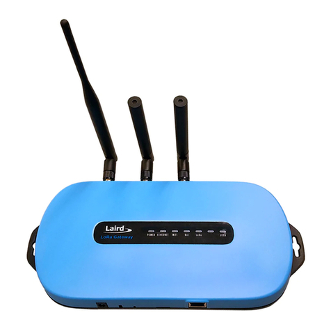
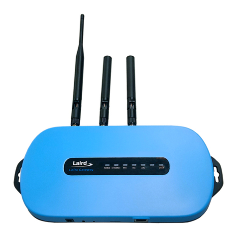
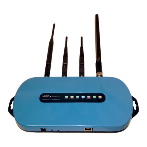
Laird’s Sentrius™ RG191+LTE LoRa-Enabled Gateway is the ultimate in secure,
scalable, robust LoRa solutions for end-to-end control of your LoRaWAN network.
Leveraging Laird’s field-proven and reliable 50 Series Wireless Bridge certified module,
it also offers enterprise dual-band Wi-Fi and wired Ethernet for complete design
freedom. Based on the Semtech SX1301/SX1257 chipset designs, it offers a LoRa
range up to ten miles and pre-loaded LoRa Packet Forwarder software options, perfect
for highly scalable, flexible IoT networks. The Sentrius RG191+LTE Gateway works
with Laird’s SentriusTM RM1xx / RS1xx Series LoRa+BLE certified modules / sensors
for simple out-of-the-box integration and is compatible with third-party cloud and LoRa
partners, as well as any LoRaWAN-certified client devices.
Figure 1: Top of the Sentrius™ RG191+LTE gateway
1. LoRa, Wi-Fi, and LTE
Antennas
2. LEDs
3. Mounting Holes
4. User Button
Figure 2: Side panel of the Sentrius™ RG191+LTE gateway
1. DC power input
2. User button
3. Reset button
4. SD card slot
5. Ethernet connector
http://www.lairdconnect.com
5
© Copyright 2020 Laird Connectivity, Inc..
All Rights Reserved
Americas: +1-800-492-2320
Europe: +44-1628-858-940
Hong Kong: +852 2923 0610
Category
Feature
Specification
Chipset
LoRa®
Semtech SX1301/SX1257
Bluetooth®
Cambridge Silicon Radio CSR8811 A08
LTE CAT 1
Quectel EG91-NA
Wi-Fi
Qualcomm Atheros QCA6004
Wireless Characteristics
Wi-Fi Spatial Streams
2x2 MIMO
Wi-Fi Frequencies
2.4 and 5 GHz operation
Conducted Maximum Transmit Power
Note: Transmit power on each channel
varies according to individual country
regulations. All values for lowest data
rate are nominal, +/-2 dBm.
Others are +/-2.5 dBm
Note:
HT40 –40 MHz-wide channels
HT20 –20 MHz-wide channels
802.11a (UNII-1, UNII-2A, UNII-2C) or CH 36 –CH140
6 Mbps
17 dBm
54 Mbps
14 dBm
802.11a (UNII-3) or CH 148 –CH 165
6 Mbps
15 dBm
54 Mbps
14 dBm
802.11b
1 Mbps
17 dBm
11 Mbps
17 dBm
802.11g
6 Mbps
17 dBm
54 Mbps
14 dBm
802.11n (2.4 GHz)
6.5 Mbps (MCS0)
17 dBm
65 Mbps (MCS7)
13 dBm
802.11n (5 GHz) (UNII-1, UNII-2A, UNII-2C) or
CH 36 –CH140
6.5 Mbps (MCS0, HT20)
17 dBm
65 Mbps (MCS7, HT20)
13 dBm
(MCS0, HT40)
14 dBm
(MCS7, HT40)
11 dBm
802.11n (5 GHz) (UNII-3) or CH 148 –CH 165
6.5 Mbps (MCS0, HT20)
15 dBm
65 Mbps (MCS7, HT20)
12 dBm
(MCS0, HT40)
14 dBm
(MCS7, HT40)
11 dBm
1 Mbps
6 dBm
Wi-Fi Radio
Conducted Typical Receiver
Sensitivity
Note: All values nominal, ±3 dBm.
Variant by channels.
802.11a
6 Mbps
-92 dBm
54 Mbps
-74 dBm (PER <= 10%)
802.11b
1 Mbps
-94 dBm
11 Mbps
-87 dBm (PER <= 8%)
802.11g
6 Mbps
-91 dBm
54 Mbps
-74 dBm (PER <= 10%)
802.11n (2.4 GHz)
6.5 Mbps (MCS0)
-91 dBm
65 Mbps (MCS7)
-71 dBm
http://www.lairdconnect.com
6
© Copyright 2020 Laird Connectivity, Inc..
All Rights Reserved
Americas: +1-800-492-2320
Europe: +44-1628-858-940
Hong Kong: +852 2923 0610
Category
Feature
Specification
802.11n (5 GHz HT20)
6.5 Mbps (MCS0)
-92 dBm
65 Mbps (MCS7)
-71 dBm
LoRa - Wireless
Characteristics
LoRa Frequencies, LoRaWAN Region,
UL/DL, Laird Connectivity part number
US
902 –928 MHz (LoRaWAN US902-928, UL) –RG191
LoRa Radio Conducted TX Power
(at -40°C)
(RG191 plus AS915 & AU923 variants)
US
28 dBm (max entry in Radio TX Power Table)
LoRa Radio Conducted RX Sensitivity
(RG191 plus AS915 & AU923 variants)
-127 dBm (Bandwidth = 125 kHz, Spreading Factor = 7, DR0)
LoRa Radio Conducted TX Power
(at -40°C) (RG186)
Supports TX power as per ETSI Frequency bands
25 dBm (max entry in Radio TX Power Table)
-3 dBm (min entry in Radio TX Power Table)
LoRa Radio Conducted RX Sensitivity
(RG186)
-125 dBm (Bandwidth = 125 kHz, Spreading Factor = 7, DR0)
-123 dBm (Bandwidth = 250 kHz, Spreading Factor = 7, DR6)
Interfaces
Wired
Ethernet - RJ45 Connector
Wireless
LoRa, 802.11, Cellular LTE
Power
Supply Voltage
12V/1A
Power Adapter
External DC Power Supply (has 12V /2A rating) with regional
plug adapter
Security
Wi-Fi
Standards –WEP, WPA, WPA2
Encryption –WEP, TKIP, AES
EAP Types –EAP-FAST, EAP-TLS, EAP-TTLS, PEAP-GTC,
PEAP-MSCHAP, PEAP-MSCHAPv2, PEAP-TLS, LEAP
Software
Operating System
Embedded Linux, 4.x Kernel
LoRa
Packet Network Forwarder with default support for the
following:
▪The Things Network with Semtech Basic Station or UDP
forwarder
▪Stream communications with UDP forwarder
▪ChirpStack with UDP forwarder or Semtech Basic Station
▪Senet through legacy Semtech UDP or proprietary Senet
forwarder
Configuration
Web-based interface via Ethernet/Wi-Fi
Physical
Dimensions
133 x 275 x 30 mm (enclosure only)
Environmental
Operating Temperature
-30° to +70°C
Note: The RG191+LTE gateway operating temperature range
is limited to -30° to +70°C due to the supplied external
power supply. The RG191+LTE gateway without the
external power supply is certified for -40° to +85°C.
Approvals (RG191+LTE)
FCC –Contains FCC ID: SQG-WB50NBT
IC –Contains IC ID: 3147A-WB50NBT
FCC –Contains FCC ID: SQG-1001
IC –Contains IC ID: 31347A-1001
FCC –Contains FCC ID: SQG-RG191NALTE
IC –Contains IC ID: 3147A-RG191NALTE
Wi-Fi Antenna
Model
Laird MAF94051
Type
Dipole
Connector
RP-SMA
http://www.lairdconnect.com
7
© Copyright 2020 Laird Connectivity, Inc..
All Rights Reserved
Americas: +1-800-492-2320
Europe: +44-1628-858-940
Hong Kong: +852 2923 0610
Category
Feature
Specification
Antenna Gain
2.1 dBi (2.4-2.5 GHz), 2.4 dBi (4.9 GHz) 2.6 dBi (5.25 GHz),
3.4 dBi (5.875 GHz)
LoRa Antenna
Model
Laird 001-0002 (902-928 MHz) used with RG191+LTE
Type
Dipole
Connector
RP-SMA
Antenna Gain
2.0 dBi (902-928 MHz) used with RG191
LTE Antenna
Model
Laird Blade: DBA6927C-FSMAM
Type
Dipole
Connector
RP-SMA
Antenna Gain
Up to 2.2dBi
Accessories
Included
1 x 902-928 MHz antenna
1 x LTE antenna
2 x 2.4/5 GHz Wi-Fi antennas
1 x External DC power adapter
Enclosure
Standard
Moulded plastic housing
Warranty
One-year warranty
Table 1: Ordering information
Part Number
Description
450-00107-K1
Kit, Sentrius RG191 Gateway, LTE, CAT-1, NA
450-00109-K1
Kit, Sentrius RG191 Gateway, LTE, CAT-1, NA, IP67
Accessories
690-1002
Pole Mount Bracket - Accessory for 450-0190, 450-0191 or 450-00109-K1
690-1003
Wall Mount Bracket - Accessory for 450-0190, 450-0191 or 450-00109-K1
http://www.lairdconnect.com
8
© Copyright 2020 Laird Connectivity, Inc..
All Rights Reserved
Americas: +1-800-492-2320
Europe: +44-1628-858-940
Hong Kong: +852 2923 0610
To use the gateway, you must power up the gateway and access the web interface via the Ethernet port. To do this, follow
these steps:
1. Follow the label on the box and connect the four antennas. Refer to Antenna Configuration for additional
information.
2. Connect the power supply (see #2 in Figure 3).
3. Connect the gateway to your router (#3 in Figure 3) using the Ethernet cable (#1 in Figure 3).
Alternatively use the Wi-Fi Quick Config mechanism. Refer to Wi-Fi Quick Configuration for additional information.
Your gateway is now connected and ready.
Figure 3: Connecting the gateway
1
2
3
http://www.lairdconnect.com
9
© Copyright 2020 Laird Connectivity, Inc..
All Rights Reserved
Americas: +1-800-492-2320
Europe: +44-1628-858-940
Hong Kong: +852 2923 0610
To utilize the LTE functionality, a cellular provider’s SIM card needs to be installed into the gateway. The recommended SIM
card to purchase shall support LTE-CAT 1, in order to utilize the full capabilities of the LTE gateway.
Note: RG191+LTE production units come with a Truphone SIM card pre-installed. The SIM will need to be registered
and activated, see 5.2.
To install the SIM card, follow these steps:
1. Unscrew the four (4) back Torx screws using a T8 Torx screwdriver for the non-IP67 gateway version.
Unscrew the thirteen (13) screws using a Philips screwdriver for the IP67 gateway version.
Figure 4: Gateway Screw Locations (Left: Standard; Right: IP67)
2. Carefully move the top enclosure lid to the back of the gateway for the indoor (non-IP67) version as seen
below. Remove the top lid for the IP67 gateway version (RF cables are not connected to the top cover on the
IP67 gateway).
Figure 5: Opened Gateway (indoor (non-IP67) gateway shown)
Note: The RF cables are connected to the modules and glued in position. If the antennas are installed, remove
the antennas before moving the top enclosure in position for the indoor (non-IP67) gateway.
http://www.lairdconnect.com
10
© Copyright 2020 Laird Connectivity, Inc..
All Rights Reserved
Americas: +1-800-492-2320
Europe: +44-1628-858-940
Hong Kong: +852 2923 0610
3. If replacing the production installed SIM card, punch out the Micro-SIM (3FF size) from the Main Sim card
(secondary set of punch out lines from the center moving outward).
Figure 6: SIM Card Punch-Out
4. Install the SIM card into the SIM card slot in the upper right location near the LTE modem making sure the copper
contact side of the SIM card is facing down (follow Blue Arrow). Re-close the gateway and screw down the screws
when complete.
Figure 7: SIM Install (Right: Picture of SIM card contact side)
Note: To remove the SIM card, push the card out from Red Arrow side and remove SIM.