manuals.online logo
Brands
  1. Home
  2. •
  3. Brands
  4. •
  5. Laird
  6. •
  7. Microcontroller
  8. •
  9. Laird DVK-BT900-S Series Quick setup guide

Laird DVK-BT900-S Series Quick setup guide

This manual suits for next models

2

Other Laird Microcontroller manuals

Laird DVK-WLM400 User manual

Laird

Laird DVK-WLM400 User manual

Laird BL654PA User manual

Laird

Laird BL654PA User manual

Laird BTM510 User manual

Laird

Laird BTM510 User manual

Laird BL654 User manual

Laird

Laird BL654 User manual

Laird DVK-BT730-SA User manual

Laird

Laird DVK-BT730-SA User manual

Laird Sterling-EWB User manual

Laird

Laird Sterling-EWB User manual

Laird BL600 Series User manual

Laird

Laird BL600 Series User manual

Laird BTM410 User manual

Laird

Laird BTM410 User manual

Laird RAMP-AC RF User manual

Laird

Laird RAMP-AC RF User manual

Laird BT830 Quick setup guide

Laird

Laird BT830 Quick setup guide

Laird DVK-SU60-2230C User manual

Laird

Laird DVK-SU60-2230C User manual

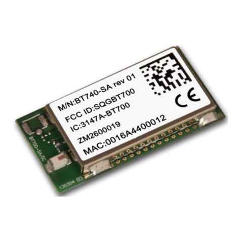
Laird BT740 Series User manual

Laird

Laird BT740 Series User manual

Laird BL652 User manual

Laird

Laird BL652 User manual

Laird Vela IF820 User manual

Laird

Laird Vela IF820 User manual

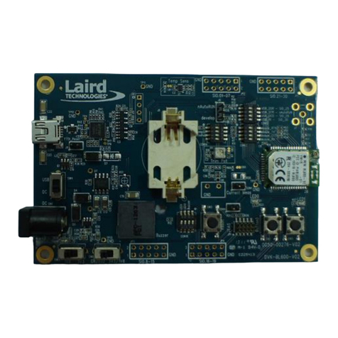
Laird DVK-BL600-SA User manual

Laird

Laird DVK-BL600-SA User manual

Laird Pinnacle 100 User manual

Laird

Laird Pinnacle 100 User manual

Laird RAMP User manual

Laird

Laird RAMP User manual

Laird BT830 Quick setup guide

Laird

Laird BT830 Quick setup guide

Laird DVK-BTM46 Series User manual

Laird

Laird DVK-BTM46 Series User manual

Laird RM024 User manual

Laird

Laird RM024 User manual

Popular Microcontroller manuals by other brands

Microsemi IGLOO nano Starter Kit user guide

Microsemi

Microsemi IGLOO nano Starter Kit user guide

GOWIN DK START GW1NSR-LV4CQN48PC7I6 V 1.1 user guide

GOWIN

GOWIN DK START GW1NSR-LV4CQN48PC7I6 V 1.1 user guide

HETRONIC ERGO-S Service manual

HETRONIC

HETRONIC ERGO-S Service manual

Novatek NT6861 manual

Novatek

Novatek NT6861 manual

Lantronix Intrinsyc Open-Q 865XR SOM user guide

Lantronix

Lantronix Intrinsyc Open-Q 865XR SOM user guide

Nuvoton ISD61S00 ChipCorder Design guide

Nuvoton

Nuvoton ISD61S00 ChipCorder Design guide

STMicrolectronics ST7 Assembler Linker user manual

STMicrolectronics

STMicrolectronics ST7 Assembler Linker user manual

Texas Instruments Chipcon CC2420DK user manual

Texas Instruments

Texas Instruments Chipcon CC2420DK user manual

NEC 78GK0S/K 1+ Series Application note

NEC

NEC 78GK0S/K 1+ Series Application note

Mikroe SEMITECH N-PLC Click Application note

Mikroe

Mikroe SEMITECH N-PLC Click Application note

Intel Agilex user guide

Intel

Intel Agilex user guide

DIGITAL-LOGIC MICROSPACE manual

DIGITAL-LOGIC

DIGITAL-LOGIC MICROSPACE manual

Texas Instruments TMS320F2837 D Series Workshop Guide and Lab Manual

Texas Instruments

Texas Instruments TMS320F2837 D Series Workshop Guide and Lab Manual

CYPRES CY14NVSRAMKIT-001 user guide

CYPRES

CYPRES CY14NVSRAMKIT-001 user guide

Espressif Systems ESP8266EX Programming guide

Espressif Systems

Espressif Systems ESP8266EX Programming guide

Abov AC33M8128L user manual

Abov

Abov AC33M8128L user manual

Silicon Laboratories C8051F800 user guide

Silicon Laboratories

Silicon Laboratories C8051F800 user guide

Energy micro EFM32 Giant Gecko Starter Kit user manual

Energy micro

Energy micro EFM32 Giant Gecko Starter Kit user manual

manuals.online logo
manuals.online logoBrands
  • About & Mission
  • Contact us
  • Privacy Policy
  • Terms and Conditions

Copyright 2025 Manuals.Online. All Rights Reserved.

DVK-BT900-Sx Development Kit
Hardware Integration Guide
Version 1.0
DVK-BT900-SA, DVK-BT900-SC
Laird Technologies
Americas: +1-800-492-2320
Europe: +44-1628-858-940
Hong Kong: +852 2923 0610
Embedded Wireless Solutions Support Center: http://ews-support.lairdtech.com
www.lairdtech.com/bluetooth
BT900 Development Kit
Version 0.3
Embedded Wireless Solutions Support Center:
http://ews-support.lairdtech.com
www.lairdtech.com/wireless
2
Laird Technologies
Americas: +1-800-492-2320
Europe: +44-1628-858-940
Hong Kong: +852-2268-6567 x026
REVISION HISTORY
Revision
Date
Changes
1.0
07 Nov 2014
Initial version
BT900 Development Kit
Version 0.3
Embedded Wireless Solutions Support Center:
http://ews-support.lairdtech.com
www.lairdtech.com/wireless
3
Laird Technologies
Americas: +1-800-492-2320
Europe: +44-1628-858-940
Hong Kong: +852-2268-6567 x026
CONTENTS
Contents ...............................................................................................................................................................3
1Laird DVK-BT900-Sx Development Kit ...........................................................................................................4
2Overview .........................................................................................................................................................4
2.1 Introduction ..............................................................................................................................................4
2.2 Package Contents......................................................................................................................................4
3DVK-BT900–Main Development Board.........................................................................................................5
3.1 Key Features..............................................................................................................................................5
3.2 Understanding the Development Board......................................................................................................6
4Functional Blocks ............................................................................................................................................8
4.1 Power Supply ............................................................................................................................................8
4.2 Reset Button..............................................................................................................................................9
4.3 4-Wire UART Serial Interface......................................................................................................................9
4.3.1 UART Mapping .............................................................................................................................9
4.3.2 UART Interface Driven by USB .......................................................................................................9
4.3.3 UART Interface Driven by External Source....................................................................................10
4.4 nAutoRUN Pin and Operating Modes.......................................................................................................11
4.5 OTA (Over the Air)
smart
BASIC application download .............................................................................12
4.6 VSP (Virtual Serial Port) connection to Host device....................................................................................12
5Software ........................................................................................................................................................13
6Breakout Connector Pinouts ........................................................................................................................14
6.1 JP2, JP3, JP4, JP5 SIO (Special Input / Output Sockets) Breakout Connectors...........................................14
6.1.1 JP2 ............................................................................................................................................. 14
6.1.2 JP3 ............................................................................................................................................. 15
6.1.3 JP4 ............................................................................................................................................. 16
6.1.4 JP5 BT-Wi-Fi Coexistence ............................................................................................................16
6.2 Additional Peripherals / Sensors ...............................................................................................................16
6.2.1 Buzzer ........................................................................................................................................17
6.2.2 Temperature Sensor....................................................................................................................18
6.2.3 Trim Potentiometer.....................................................................................................................19
6.2.4 Push Buttons and LEDs................................................................................................................20
6.2.5 I2C device...................................................................................................................................21
6.2.6 SPI device ...................................................................................................................................21
7Other Features ..............................................................................................................................................22
7.1 Current Consumption Measurement........................................................................................................22
8Additional Documentation ..........................................................................................................................24
BT900 Development Kit
Version 0.3
Embedded Wireless Solutions Support Center:
http://ews-support.lairdtech.com
www.lairdtech.com/wireless
4
Laird Technologies
Americas: +1-800-492-2320
Europe: +44-1628-858-940
Hong Kong: +852-2268-6567 x026
1LAIRD DVK-BT900-SX DEVELOPMENT KIT
Part number: DVK-BT900-SA / DVK-BT900-SC
Applicable to the following module part numbers:
BT900-SA Intelligent BTv4.0 Dual Mode Module featuring
smart
BASIC (internal antenna)
BT900-SC Intelligent BTv4.0 Dual Mode Module featuring
smart
BASIC (u.FL connector)
2OVERVIEW
The Laird DVK-BT900 development kit provides a platform for rapid wireless connectivity prototyping, providing
multiple options for the development of Classic Bluetooth and Bluetooth Low Energy (BLE) applications.
This manual is for Rev. 01 and later of the development PCB and relates to DVK-BT900-V01 and later on the
silkscreen of the PCB motherboard itself. The complete functionality of the development kit hardware requires the
use of Laird BT900 series
smart
BASIC runtime engine FW version v9.1.2.0 or greater.
2.1 Introduction
The development kit is designed to support the rapid development of applications and software for the BT900 series
of BT / BLE modules featuring Laird’s innovative event driven programming language –
smart
BASIC. More
information regarding this product series (including a detailed module User’s Manual and
smart
BASIC
user guide) is
available on the Laird’s BT900 product pages.
2.2 Package Contents
All kits contain the following items:
Development
Board
The development board has the required BT900 module already soldered onto it and exposes
all the various hardware interfaces available.
Power Option
USB cable –Type A to mini type B. The cable also provides serial communications via the FTDI
USB –RS232 converter chip on the development board.
Pin Headers x 4
Supplied to allow simple connection to SIO lines via the through hole plated areas JP2, JP3,
JP4 and JP5. The headers are 2 x 5 way and are 2.54 mm pitch.
Jumper Pin
Cables x 6
Supplied to allow simple connection to the various pin headers for prototyping purposes.
Web link Card
Provides links to additional information including the BT900 user manual, firmware, Laird
BT900 mobile apps, terminal utilities, schematics, quick start guides, and firmware release
notes.
BT900 Development Kit
Version 0.3
Embedded Wireless Solutions Support Center:
http://ews-support.lairdtech.com
www.lairdtech.com/wireless
5
Laird Technologies
Americas: +1-800-492-2320
Europe: +44-1628-858-940
Hong Kong: +852-2268-6567 x026
3DVK-BT900–MAIN DEVELOPMENT BOARD
This section describes the BT900 development board hardware. The BT900 development board is delivered with the
BT900 series module loaded with integrated
smart
BASIC runtime engine FW but no onboard
smart
BASIC
application; because of this, it starts up in AT command mode by default.
smart
BASIC applications are simple and easy to develop for any BT / BLE application. Sample
smart
BASIC
applications are available to download from the Laird’s BT900 product pages or via the Technical Support Site
https://laird-ews-support.desk.com/
The BT900 development board is a universal development tool to highlight the capabilities of the BT900 module. The
development kit is supplied in a default configuration which should be suitable for multiple experimentation options.
It also offers a number micro-DIP switches that help isolate on-board sensors and UART from the BT900 module to
create different configurations. This allows you to test different operating scenarios.
The development board allows the BT900 series module to physically connect to a PC via the supplied USB cable for
development purposes. The development board provides USB-to-Virtual COM port conversion through a FTDI chip –
part number FT232R. Any Windows PC (XP or later) should auto-install the necessary drivers; if your PC cannot locate
the drivers, you can download them from http://www.ftdichip.com/Drivers/VCP.htm
3.1 Key Features
The BT900 development board has the following features:
BT900 series module soldered on-board.
Power supply options for powering development board from:
-USB
-external DC supply
-AAA batteries (3xAAA battery holder fitted on underside of development board)
Regulated 3.3 V for powering the BT900 module. Optional regulated 1.8 V for powering the BT900 module.
NOTE: 1.8V operation not supported in BT900 module
smart
BASIC runtime engine FW v9.1.2.0.
USB to UART bridge (FTDI chip).
BT900 UART can be interfaced to:
-USB (PC) using the USB-UART bridge
-External UART source (using IO break-out connector when development board powered from DC jack)
Current measuring (for BT900 module only) options:
-Pin header (Ammeter)
-Current shunt monitor IC (volt meter or oscilloscope)
-Series resistor for differential measurement (oscilloscope)
IO break-out (four 2x5-pin 2.54mm pitch headers) connectors interface for plugging-in external
modules/sensors, and accessing all interfaces of the BT900 module [UART, SPI, I2C, SIO (DIO or AIN (ADCs)),
PWM, FREQ].
Two Buttons and two LEDs for user interaction.
Two on-board sensors (analogue output): Temperature and Trim Pot.
One buzzer.
One on-board SPI sensor/device (serial Eeprom).
One on-board I2C sensor /device (RTC chip).
Micro DIP switches that allow the on-board sensors, LED’s (and USB UART FTDI bridge) to be disconnected
from BT900 module.
BT900 Development Kit
Version 0.3
Embedded Wireless Solutions Support Center:
http://ews-support.lairdtech.com
www.lairdtech.com/wireless
6
Laird Technologies
Americas: +1-800-492-2320
Europe: +44-1628-858-940
Hong Kong: +852-2268-6567 x026
External 32.768 kHz crystal oscillator (for Laird use or future use). Not required for use with BT900 and
therefore is disabled by jumper fitted on CON6.

smart
BASIC runtime engine FW upgrade capability:
-Via UART (using the FTDI USB-UART).

smart
BASIC application script loading capability:
-Via UART (using the FTDI USB-UART).
-Via OTA (Over the Air)
3.2 Understanding the Development Board
Figure 1: BT900 development board
FTDI-FT232R
JP5 BT-WiFi
coexist pins
DIP Switch
CON14
DIP Switch CON13
Buzzer
BZ1
DC Jack
Input CN1
DC/USB
Power Source
Switch SW4
USB CON4
BT900-Sx
Module
LED2
LED1
DIP Switch
CON15
Button 2
SW3
Button1
SW1
Reset SW2
CON17
DIP Switch
CON12
Current
Measure
BT900 Development Kit
Version 0.3
Embedded Wireless Solutions Support Center:
http://ews-support.lairdtech.com
www.lairdtech.com/wireless
7
Laird Technologies
Americas: +1-800-492-2320
Europe: +44-1628-858-940
Hong Kong: +852-2268-6567 x026
Important! To ensure correct ‘out of the box’ configuration, the BT900 development board must be set
according to Figure 2.
Figure 2: Correct development board settings
Note: nAutoRUN jumper must be placed on
pins 2 and 3 as shown.
Note: Disable Temp Sensor
and Trim Pot for lowest
power consumption by
setting to OFF position.
Note: Jumper is fitted
over two pins of
CON1
BT900 Development Kit
Version 0.3
Embedded Wireless Solutions Support Center:
http://ews-support.lairdtech.com
www.lairdtech.com/wireless
8
Laird Technologies
Americas: +1-800-492-2320
Europe: +44-1628-858-940
Hong Kong: +852-2268-6567 x026
4FUNCTIONAL BLOCKS
The development board is formed from the following major functional blocks:
4.1 Power Supply
Figure 3: BT900 devboard power supply
The development board can be powered from 4.5-5.5 V supply (into DC jack connector CN1), 3 AAA batteries
(holder J7 mounted on underside of board), or from the USB (type mini-B connector or CON4). The power source fed
into DC jack (CN1) or 3 AAA batteries (J7) is combined together through diodes (diode-OR) and fed to the SW4
switch that allows selection of power source between either USB or the DC jack/AAA.
The 5V from the USB or the DC jack/AAA batteries is regulated down to 3.3V with an on-board regulator on the
development board.
The CON17 default is to select regulated 3.3V.
Note: The development board has a 1.8V regulator for the possibility of powering the BT900 module from a
1.8V rail (by changing the CON17 position). BT900 1.8V operation is not supported in the current
firmware (v9.1.2.0).
The development board’s 3.3V regulator provides power to the BLE module and USB UART bridge interface as well as
to sensors on the development board.
Switch Positions
Development Board Power Source
SW4
CON17 select BT900 Power source
USB (CON4)
Position USB
Position 3.3V always
(for 3.3V operation)
DC jack (CN1) or AAA battery (J7).Note 1
Position DC
Position 3.3V always
(for 3.3V operation)
Note 1: The development board is powered from DC jack (or AAA batteries) when an external UART source is
to be interfaced to BT900 module (using breakout connector JP5).
On the development board, the power domain:
VCC_BT supplies the BT900 series module only. Current measuring block on development board only
measures the current into power domain VCC_BT and VREG_IN_HV, VDD_PADS (when the BT900 is powered
by 3.3V (CON17 in the 3.3V position).
VREG_IN_HV, VDD_PADS supplies the BT900 module (BT radio chip section) only.
VCC_IO_UART supplies the FTDI chip IO and all other sensors and circuitry.
BT900 Development Kit
Version 0.3
Embedded Wireless Solutions Support Center:
http://ews-support.lairdtech.com
www.lairdtech.com/wireless
9
Laird Technologies
Americas: +1-800-492-2320
Europe: +44-1628-858-940
Hong Kong: +852-2268-6567 x026
VCC_IO is wired to the header connectors (JP2, JP3, JP4, JP5) via R29 and can be used to power external
devices sensors.
4.2 Reset Button
The development board has a reset button (SW2). The reset is active low (SW2 pushed down). To view its location,
refer to Error! Reference source not found..
4.3 4-Wire UART Serial Interface
The development board provides access to the BT900 module 4-wire UART interface (TX, RX, CTS, RTS) either
through USB (via U9 FTDI USB-UART convertor chip) or through a breakout header connector J10. Refer to Figure 4.
Note: BT900 module provides 4-wire UART interface on the HW and the other four signals (DTR, DSR, DCD, RI)
which are low bandwidth signals can be implemented in a
smart
BASIC application, using any spare digital
SIO pins.
4.3.1 UART Mapping
UART connection on the BT900 series module and FTDI IC are shown in table below. Refer to Figure 4 to see how the
BT900 series module UART is mapped to the breakout header connector (J10).
Table 1: UART mapping
BT900 SIO
BT900 Default function
FTDI IC UART
SIO.1
UART_TX (output)
USB_RX
SIO.0
UART_RX (input)
USB_TX
SIO.2
UART_RTS (output)
USB_CTS
SIO.3
UART_CTS (input)
USB_RTS
Additional SIO pins are also routed to the FTDI chip via a switch block. For example, the nAutoRUN input pin on the
module can be driven by the DTR output pin of the FTDI chip. This allows testing the $autorun$ application on boot.
4.3.2 UART Interface Driven by USB
USB Connector. The development kit provides a USB Type mini-B connector (CON4) which allows connection
to any USB host device. The connector optionally supplies power to the development kit and the USB signals
are connected to a USB to serial convertor device (FT232R), when SW4 is set to ‘USB’ position.
USB –UART. The development kit is fitted with a (U9) FTDI FT232R USB to UART converter which provides
USB-to-Virtual COM port on any Windows PC (XP or later). Upon connection, Windows auto-installs the
required drivers. For more details and driver downloads, visit http://www.ftdichip.com/Products/FT232R.htm.
UART interface driven by USB FTDI chip. In normal operation, the BT900 UART interface is driven by the FTDI
FT232R USB to UART converter in the development board. This is used for the BT900 series module
smart
BASIC runtime engine FW upgrade or to load
smart
BASIC application script.
BT900 Development Kit
Version 0.3
Embedded Wireless Solutions Support Center:
http://ews-support.lairdtech.com
www.lairdtech.com/wireless
10
Laird Technologies
Americas: +1-800-492-2320
Europe: +44-1628-858-940
Hong Kong: +852-2268-6567 x026
4.3.3 UART Interface Driven by External Source
UART interface driven by external UART source. The BT900 module UART interface (TX, RX, CTS, RTS) is
presented at a 2.54 mm (0.1”) pitch header (J10). To allow the BT900 UART interface to be driven from the
breakout header connector (J10):
-The development board must be powered from a DC jack (CN1) or AAA batteries (J7) and switch SW4
must be in DC position.
-The FTDI device must be held in reset which is achieved automatically by removal of USB cable or SW4 is in
the DC position.
-Micro-DIP switch CON13 allows the four BT900 UART pins to be physically isolated as well from USB-UART
FTDI device. Physical micro-DIP switch body has text “ON”on the closed side. By default, CON13 is closed.
Figure 4: USB to UART Interface and Header to UART interface
J10 pin-out is designed to be used with an external FTDI USB to UART TTL (3.3V) convertor cables:
http://www.ftdichip.com/Products/Cables/USBTTLSerial.htm
E.g. FTDI manufacturer part number for cable: TTL-232R-3V3